Trusted Business
Verified & Licensed
Virus Free Files
100% Safe Downloads
Secure Payment
SSL Protected
Instant Delivery
Available Immediately
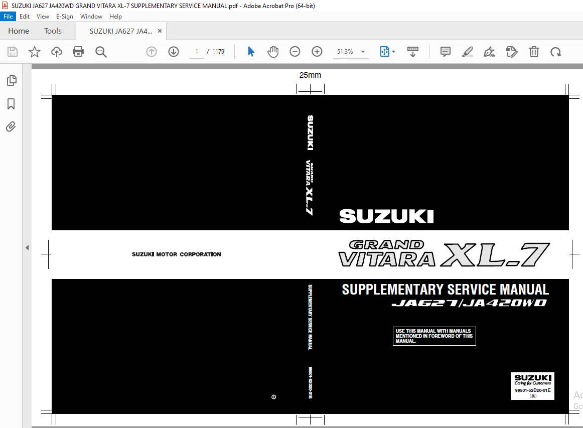
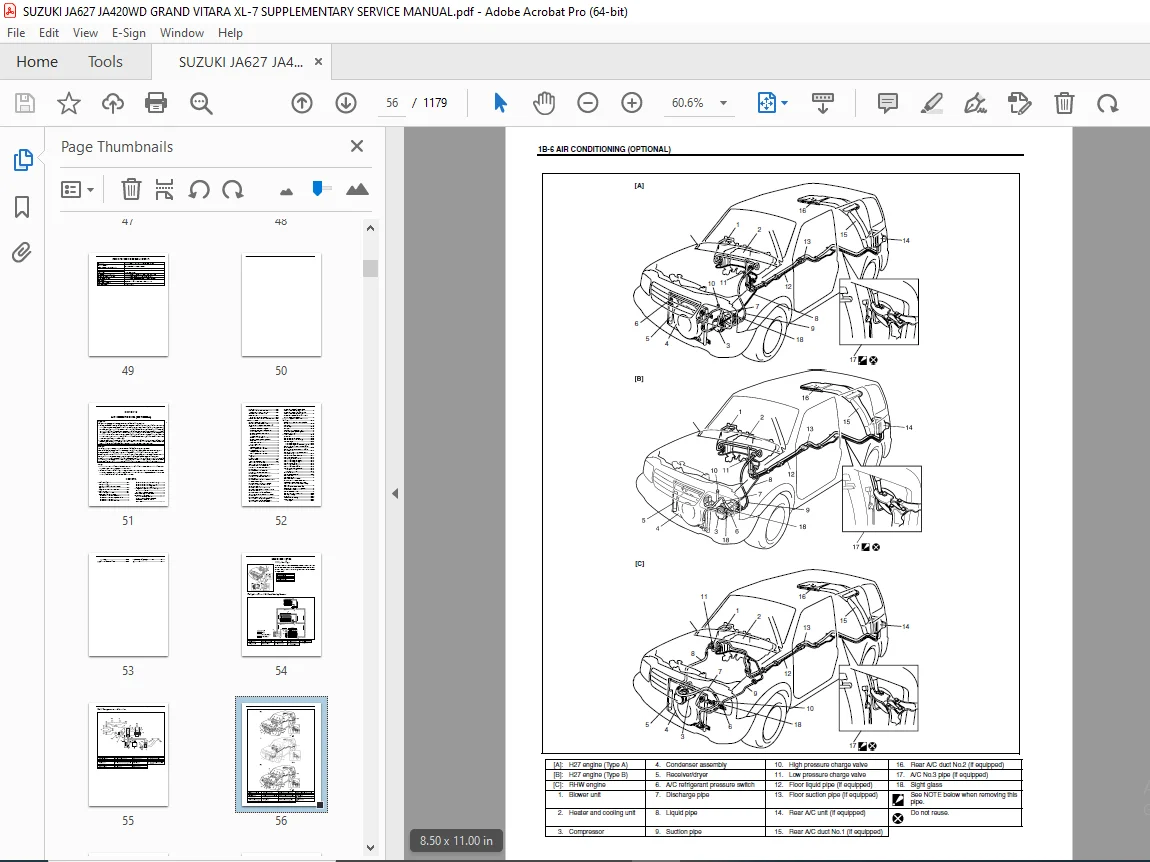
SUZUKI JA627 JA420WD GRAND VITARA XL-7 SUPPLEMENTARY SERVICE MANUAL – PDF DOWNLOAD
$35.95
Instant PDF Download
Available immediately
Save to Your Device
Download & keep forever
Antivirus Scanned
100% virus-free
Trusted Worldwide
175,000+ customers
Description
SUZUKI JA627 JA420WD GRAND VITARA XL-7 SUPPLEMENTARY SERVICE MANUAL – PDF DOWNLOAD
FILE DETAILS:
SUZUKI JA627 JA420WD GRAND VITARA XL-7 SUPPLEMENTARY SERVICE MANUAL – PDF DOWNLOAD
Language : English
Pages : 1179
Downloadable : Yes
File Type : PDF
IMAGES PREVIEW OF THE MANUAL:
TABLE OF CONTENTS:
SUZUKI JA627 JA420WD GRAND VITARA XL-7 SUPPLEMENTARY SERVICE MANUAL – PDF DOWNLOAD
Bookcover.............................................................................................................   1
99501-52D20-01E.......................................................................................................   2
	TOP...............................................................................................................   0
	Manual List.......................................................................................................   0
	Important.........................................................................................................   2
		WARNING/CAUTION/NOTE..........................................................................................   2
	Foreword..........................................................................................................   3
	Table of Contents.................................................................................................   5
	SECTION 0A........................................................................................................   7
		Precautions...................................................................................................   8
			Precaution for Vehicles Equipped with a Supplemental Restraint (Air Bag) System...........................   8
				Diagnosis.............................................................................................   9
				Servicing and handling................................................................................  10
			General Precautions.......................................................................................  13
			Precaution for CAN Communication System...................................................................  16
		Identification Information....................................................................................  17
			Vehicle Identification Number.............................................................................  17
			Engine Identification Number..............................................................................  17
			Transmission Identification Number........................................................................  17
		Warning, Caution and Information Labels.......................................................................  18
		Vehicle Lifting Points........................................................................................  20
		Abbreviations May Be Used in This Manual......................................................................  22
		Metric Information............................................................................................  24
			Metric Fasteners..........................................................................................  24
	SECTION 0B........................................................................................................  25
		Maintenance Schedule..........................................................................................  27
			Maintenance Schedule under Normal Driving Conditions......................................................  27
			Maintenance Recommended under Severe Driving Conditions...................................................  30
		Maintenance Service...........................................................................................  32
			Engine (H27 Engine).......................................................................................  32
				Accessory drive belt (H27 Engine).....................................................................  32
				Engine oil and filter (H27 Engine)....................................................................  33
				Engine coolant (H27 Engine)...........................................................................  36
				Exhaust system (H27 Engine)...........................................................................  36
			Ignition System (H27 Engine)..............................................................................  36
				Spark plugs (H27 Engine)..............................................................................  36
			Fuel System (H27 Engine)..................................................................................  37
				Air cleaner filter (H27 Engine).......................................................................  37
				Fuel lines and connections (H27 Engine)...............................................................  37
				Fuel filter (H27 Engine)..............................................................................  38
				Fuel tank (H27 Engine)................................................................................  38
			Emission Control System (H27 Engine)......................................................................  38
				Crankcase ventilation hoses and connections (vehicle not equipped with oxygen sensor) (H27 Engine)....  38
				PCV (positive crankcase ventilation) valve (H27 Engine)...............................................  38
				Fuel evaporative emission control system (H27 Engine).................................................  39
			Engine (RHW Engine).......................................................................................  39
				Accessory drive belt (RHW Engine).....................................................................  39
				Camshaft timing belt (RHW Engine).....................................................................  40
				Engine oil and oil filter (RHW Engine)................................................................  40
				Engine coolant (RHW Engine)...........................................................................  42
				Exhaust system (RHW Engine)...........................................................................  42
				Heater (Glow) plugs (RHW Engine)......................................................................  43
			Fuel System (RHW Engine)..................................................................................  43
				Air cleaner filter (RHW Engine).......................................................................  43
				Fuel lines and connections (RHW Engine)...............................................................  44
				Fuel filter (RHW Engine)..............................................................................  44
				Fuel tank (RHW Engine)................................................................................  44
			Chassis and Body..........................................................................................  45
				Manual transmission oil...............................................................................  45
				Automatic transmission fluid..........................................................................  45
				Transfer and differential oil.........................................................................  47
				Power steering (P/S) system (if equipped).............................................................  48
		Recommended Fluids and Lubricants.............................................................................  49
	SECTION 1B........................................................................................................  51
		General Description...........................................................................................  54
			Refrigerant Type..........................................................................................  54
			Refrigerant Flow of Air Conditioning System...............................................................  54
			Major Components and Location.............................................................................  55
		General Diagnosis.............................................................................................  57
			General Diagnosis Table...................................................................................  57
			Quickly Checking of Refrigerant Charge....................................................................  62
			Performance Diagnosis.....................................................................................  64
				Performance diagnosis table...........................................................................  66
				Detail diagnosis table (at ambient temperature within 30 – 35 °C (86 – 95 °F))........................  68
			Wiring Circuit............................................................................................  70
			HVAC Control Module and Its Circuits......................................................................  75
				HVAC control module voltage table.....................................................................  76
			A/C Controller and Its Circuits (RHW Engine)..............................................................  86
				A/C controller voltage value table....................................................................  87
			ECM (PCM) and Its Circuits (H27 Engine)...................................................................  88
		HVAC Diagnosis................................................................................................  90
			Scan Tool Data............................................................................................  90
				Scan tool data definitions............................................................................  91
		Refrigerant Recovery, Evacuation and Charging.................................................................  94
			Operation Procedure for Charging A/C with Refrigerant.....................................................  94
			Evacuating................................................................................................  95
			Charging..................................................................................................  96
		On-Vehicle Service............................................................................................  99
			Precaution................................................................................................  99
			A/C Condenser Assembly.................................................................................... 103
			A/C Condenser Fan Assembly................................................................................ 105
			Receiver/Dryer............................................................................................ 107
				H27 engine (Type A)................................................................................... 107
				H27 engine (Type B) and RHW engine.................................................................... 107
			A/C Refrigerant (Triple) Pressure Switch (H27 Engine)..................................................... 109
			A/C Refrigerant (Dual) Pressure Switch (RHW engine)....................................................... 110
			A/C Compressor Relay and Condenser Fan Motor Relay........................................................ 110
			Rear A/C Unit (Rear A/C Evaporator)....................................................................... 111
			Rear Expansion Valve...................................................................................... 113
			Refrigerant Pipes and Hoses............................................................................... 113
			Rear Blower Motor Assembly................................................................................ 115
			Rear Blower Motor Relay................................................................................... 116
			Rear A/C Main Switch...................................................................................... 116
			Rear Blower Motor Resistor................................................................................ 117
			Rear Blower Motor Switch.................................................................................. 118
			Rear A/C No.1 and No.2 Duct............................................................................... 119
				Rear A/C No.1 duct.................................................................................... 119
				Rear A/C No.2 duct.................................................................................... 119
			Heater and Cooling Unit................................................................................... 120
			A/C Controller (RHW Engine)............................................................................... 122
			A/C Signal Relay.......................................................................................... 123
			Drive Belt................................................................................................ 124
			Compressor Assembly....................................................................................... 125
			Magnet Clutch............................................................................................. 129
				H27 engine............................................................................................ 129
				RHW engine............................................................................................ 132
		Required Service Materials.................................................................................... 135
		Tightening Torque Specification............................................................................... 135
		Special Tool.................................................................................................. 135
	SECTION 3A........................................................................................................ 137
		General Information........................................................................................... 137
			Caster.................................................................................................... 137
			Side Slip (Reference)..................................................................................... 137
	SECTION 3B1....................................................................................................... 139
		General Description...........................................................................................  54
			Power Steering (P/S) Pump................................................................................. 141
		Diagnosis..................................................................................................... 142
			Power Steering Fluid...................................................................................... 142
				Power steering fluid level check...................................................................... 980
			Power Steering Pump Drive Belt............................................................................ 143
				Belt inspection....................................................................................... 143
				Belt tension check.................................................................................... 143
				Belt tension adjustment............................................................................... 143
			Hydraulic Pressure in P/S Circuit......................................................................... 144
				Hydraulic pressure check.............................................................................. 144
		On-Vehicle Service............................................................................................ 146
			Power Steering Gear Box Assembly.......................................................................... 146
			Power Steering Pump (For H27 Engine Model: Type A)........................................................ 148
			Power Steering Pump (For H27 Engine Model: Type B)........................................................ 149
			Power Steering Pump (For RHW Engine Model)................................................................ 150
	SECTION 3E........................................................................................................ 157
		General Description........................................................................................... 158
		On-Vehicle Service............................................................................................ 159
			Rear Axle Shaft and Wheel Bearing......................................................................... 159
			Rear Axle Shaft Inner Oil Seal............................................................................ 163
			Rear Axle Housing......................................................................................... 164
		Tightening Torque Specification............................................................................... 172
		Required Service Material..................................................................................... 172
		Special Tool.................................................................................................. 173
	SECTION 3F........................................................................................................ 175
		General Description........................................................................................... 176
			Tires..................................................................................................... 176
			Wheels.................................................................................................... 176
	SECTION 4A2....................................................................................................... 177
		General Description........................................................................................... 178
		Diagnosis..................................................................................................... 178
			Diagnosis Table........................................................................................... 178
			Drive Shaft Boot and Joint Check.......................................................................... 178
		On-Vehicle Service............................................................................................ 179
			Drive Shaft............................................................................................... 179
			Front Drive Shaft Bearing / Oil Seal Removal and Installation............................................. 187
		Tightening Torque Specifications.............................................................................. 189
		Required Service Material..................................................................................... 189
		Special Tool.................................................................................................. 190
	SECTION 4B........................................................................................................ 191
		General Description........................................................................................... 192
			Propeller Shaft Components................................................................................ 192
				For H27 engine model.................................................................................. 192
				For RHW engine model.................................................................................. 192
		Diagnosis..................................................................................................... 193
			Diagnosis Table........................................................................................... 193
				Propeller shaft joint check........................................................................... 193
		On-Vehicle Service............................................................................................ 193
			Propeller Shaft........................................................................................... 193
		Tightening Torque Specification............................................................................... 198
		Required Service Material..................................................................................... 198
		Special Tool.................................................................................................. 198
	SECTION 5......................................................................................................... 199
		General Description........................................................................................... 200
			Brake Construction........................................................................................ 200
		Diagnosis..................................................................................................... 201
			Diagnosis Table........................................................................................... 201
		Check and Adjustment.......................................................................................... 202
			Bleeding Brakes........................................................................................... 202
	SECTION 5A........................................................................................................ 205
		General Description........................................................................................... 206
			Master Cylinder Assembly.................................................................................. 206
		On-Vehicle Service............................................................................................ 207
			Front Brake Hose/Pipe..................................................................................... 207
			Master Cylinder Reservoir................................................................................. 210
			Master Cylinder Assembly.................................................................................. 211
			Brake Booster............................................................................................. 213
		Tightening Torque Specification............................................................................... 215
		Special Tool.................................................................................................. 215
	SECTION 5B1....................................................................................................... 217
		General Description........................................................................................... 218
			Disc Brake Caliper Assembly............................................................................... 218
		Diagnosis..................................................................................................... 219
		Check and Adjustment.......................................................................................... 219
		On-Vehicle Service............................................................................................ 219
			Front Disc Brake Pad...................................................................................... 219
			Front Disc Brake Caliper.................................................................................. 222
			Front Brake Disc.......................................................................................... 226
		Tightening Torque Specification............................................................................... 227
		Required Service Material..................................................................................... 227
	SECTION 5C........................................................................................................ 229
		General Description........................................................................................... 230
			Drum Brake Assembly....................................................................................... 230
		On-Vehicle Service............................................................................................ 231
			Parking Brake Cable....................................................................................... 231
			Brake Drum................................................................................................ 233
			Brake Shoe................................................................................................ 235
			Brake Back Plate.......................................................................................... 235
		Tightening Torque Specification............................................................................... 236
	SECTION 6-1....................................................................................................... 237
		General Information........................................................................................... 240
			Statement of Cleanliness and Care......................................................................... 240
			Precaution................................................................................................ 240
				Precaution on engine service.......................................................................... 240
				Precaution on fuel system service..................................................................... 241
				Fuel pressure relief procedure........................................................................ 242
				Fuel leakage check procedure.......................................................................... 242
		Diagnosis..................................................................................................... 243
			Engine Diagnosis General Description...................................................................... 243
			On-Board Diagnostic System Description (Vehicle without Diagnosis Connector).............................. 243
			On-Board Diagnostic System Description (Vehicle with Diagnosis Connector)................................. 246
			Precaution in Diagnosing Trouble for Engine............................................................... 247
			Engine and Emission Control System Check.................................................................. 248
			Customer Problem Inspection From (Example)................................................................ 249
			Visual Inspection......................................................................................... 250
			Engine Basic Inspection................................................................................... 251
			Malfunction Indicator Lamp (MIL) Check.................................................................... 253
			Diagnostic Trouble Code (DTC) Check....................................................................... 253
			Diagnostic Trouble Code (DTC) Clearance................................................................... 254
			Diagnostic Trouble Code (DTC) Table....................................................................... 255
				For A/T system (Refer to Section 7B1 for diagnosis)................................................... 258
				For immobilizer control system (Refer to Section 8G for diagnosis).................................... 259
			Fail-Safe Table........................................................................................... 260
			Scan Tool Data............................................................................................ 261
				Scan tool data definitions............................................................................ 264
			Engine Symptom Diagnosis.................................................................................. 268
			Inspection of ECM (PCM) and Its Circuits.................................................................. 273
			Table A-1 Malfunction Indicator Lamp Circuit Check – Lamp Does Not Come “ON” or Dims at Ignition ......... 286
			Table A-2 Malfunction Indicator Lamp Circuit Check – Lamp Remains “ON” after Engine Starts................ 287
			Table A-3 Malfunction Indicator Lamp Check – MIL Flashes at Ignition Switch ON (Vehicle with Diag......... 288
			Table A-4 Malfunction Indicator Lamp Check – MIL Does Not Flash or Just Remains ON Even with Grou......... 288
			Table A-5 ECM (PCM) Power and Ground Circuit Check – MIL Doesn’t Light at Ignition Switch ON and ......... 289
			DTC P0100 (DTC No.33, 34) Mass Air Flow Circuit Malfunction............................................... 291
			DTC P0110 (DTC No.23, 25) Intake Air Temp. (IAT) Circuit Malfunction...................................... 293
			DTC P0115 (DTC No.14, 15) Engine Coolant Temp. Circuit Malfunction........................................ 294
			DTC P0120 (DTC No.21, 22) Throttle Position Circuit Malfunction........................................... 296
			DTC P0121 Throttle Position Circuit Range/Performance Problem............................................. 298
			DTC P0130 (DTC No.13) HO2S-1 (Bank 1) Circuit Malfunction or No Activity Detected......................... 300
			DTC P0133 HO2S-1 (Bank 1) Circuit Slow Response........................................................... 302
			DTC P0135 HO2S-1 (Bank 1) Heater Circuit Malfunction...................................................... 303
			DTC P0136 HO2S-2 (Bank 1) Circuit Malfunction............................................................. 305
			DTC P0141 HO2S-2 (Bank 1) Heater Circuit Malfunction...................................................... 307
			DTC P0150 (DTC No.26) HO2S-1 (Bank 2) Circuit Malfunction or No Activity Detected......................... 309
			DTC P0153 HO2S-1 (Bank 2) Circuit Slow Response........................................................... 311
			DTC P0155 HO2S-1 (Bank 2) Heater Circuit Malfunction...................................................... 312
			DTC P0156 HO2S-2 (Bank 2) Circuit Malfunction............................................................. 314
			DTC P0161 HO2S-2 (Bank 2) Heater Circuit Malfunction...................................................... 316
			DTC P0171/P0172 Fuel System Too Lean/Rich (Bank 1)........................................................ 318
			DTC P0174/P0175 Fuel System Too Lean/Rich (Bank 2)........................................................ 320
			DTC P0300/P0301/P0302/P0303/P0304/P0305/P0306 Random Misfire/Cylinder 1 Misfire/Cylinder 2 Misfir......... 322
			DTC P0325 (DTC No.43) Knock Sensor Circuit Malfunction.................................................... 324
			DTC P0335 Crankshaft Position Sensor Circuit Malfunction.................................................. 326
			DTC P0340 (DTC No.42) Camshaft Position Sensor Circuit Malfunction........................................ 328
			DTC P0400 Exhaust Gas Recirculation Flow Malfunction...................................................... 331
			DTC P0403 (DTC No.51) Exhaust Gas Recirculation Circuit Malfunction....................................... 334
			DTC P0420 Catalyst System Efficiency Below Threshold (Bank 1)............................................. 336
			DTC P0430 Catalyst System Efficiency Below Threshold (Bank 2)............................................. 338
			DTC P0443 Evap Control System Purge Control Valve Circuit Malfunction..................................... 340
			DTC P0460 Fuel Level Sensor Circuit High Input............................................................ 342
			DTC P0500 (DTC No.24) Vehicle Speed Sensor Malfunction.................................................... 344
			DTC P0505 Idle Air Control System Malfunction............................................................. 347
			DTC P0601 (DTC No.71) Internal Control Module Memory Check Sum Error...................................... 349
			DTC P1408 Manifold Absolute Pressure Sensor Circuit Malfunction........................................... 350
			DTC P1450/P1451 Barometric Pressure Sensor Circuit Malfunction/Performance Problem........................ 352
			DTC P1500 Engine Starter Signal Circuit Malfunction....................................................... 354
			DTC P1510 Ecm Back-Up Power Supply Malfunction............................................................ 356
			Table B-1 Fuel Pump Circuit Inspection.................................................................... 358
			Table B-2 Fuel Injectors and Circuit Inspection........................................................... 360
			Table B-3 Fuel Pressure Inspection........................................................................ 362
			Table B-4 Idle Air Control System Inspection.............................................................. 364
			Table B-5 A/C Signal Circuits Inspection (If Equipped).................................................... 366
			Table B-6 A/C Condenser Fan Motor Relay Low Speed Control System Inspection (If Equipped)................. 367
			Table B-7 A/C Condenser Fan Motor Relay High Speed Control System Inspection (If Equipped)................ 369
			Table B-8 A/C Compressor Relay Control System Inspection (If Equipped).................................... 371
		Special Tool.................................................................................................. 373
	SECTION 6-2....................................................................................................... 375
		General Information........................................................................................... 378
			Statement of Cleanliness and Care......................................................................... 378
			Precaution................................................................................................ 378
				Precaution on engine service.......................................................................... 378
				Precaution on fuel system service..................................................................... 379
				Fuel pressure relief procedure........................................................................ 380
				Fuel leakage check procedure.......................................................................... 380
		Diagnosis..................................................................................................... 381
			Engine Diagnosis General Description...................................................................... 381
			On-Board Diagnostic System Description (Vehicle without Diagnosis Connector).............................. 381
			On-Board Diagnostic System Description (Vehicle with Diagnosis Connector)................................. 384
			Precaution in Diagnosing Trouble for Engine............................................................... 385
			Engine and Emission Control System Check.................................................................. 386
			Customer Problem Inspection Form (Example)................................................................ 387
			Visual Inspection......................................................................................... 388
			Engine Basic Inspection................................................................................... 389
			Malfunction Indicator Lamp (MIL) Check.................................................................... 391
			Diagnostic Trouble Code (DTC) Check....................................................................... 391
			Diagnostic Trouble Code (DTC) Clearance................................................................... 392
			Diagnostic Trouble Code (DTC) Table....................................................................... 393
				For vehicle with diagnosis connector.................................................................. 393
				For vehicle without diagnosis connector............................................................... 394
				For A/T System (Only OBD Generic Scan Tool Is Displayed on the Following DTC(s) at the Same Time)..... 397
				For immobilizer control system (Refer to Section 8G for diagnosis).................................... 398
			Fail-Safe Table........................................................................................... 399
				For vehicle with diagnosis connector.................................................................. 399
				For vehicle without diagnosis connector............................................................... 399
			Scan Tool Data............................................................................................ 400
				Scan tool data definitions............................................................................ 402
			Engine Symptom Diagnosis.................................................................................. 406
			Inspection of ECM and Its Circuits........................................................................ 412
			Table A-1 Malfunction Indicator Lamp Circuit Check – Lamp Does Not Come “ON” or Dims at Ignition ......... 424
			Table A-2 Malfunction Indicator Lamp Circuit Check – Lamp Remains “ON” after Engine Starts................ 425
			Table A-3 Malfunction Indicator Lamp Check – MIL Flashes at Ignition Switch ON (Vehicle with Diag......... 426
			Table A-4 Malfunction Indicator Lamp Check – MIL Does Not Flash or Just Remains ON Even with Grou......... 426
			Table A-5 ECM Power and Ground Circuit Check – MIL Doesn’t Light at Ignition Switch ON and Engine......... 427
			DTC P0031/P0032 HO2S (Bank 1 Sensor-1) Heater Control Circuit Low/High.................................... 429
			DTC P0037/P0038 HO2S (Bank 1 Sensor-2) Heater Control Circuit Low/High.................................... 431
			DTC P0051/P0052 HO2S (Bank 2 Sensor-1) Heater Control Circuit Low/High.................................... 434
			DTC P0057/P0058 HO2S (Bank 2 Sensor-2) Heater Control Circuit Low/High.................................... 436
			DTC P0100 (DTC No.33, 34) Mass Air Flow Circuit Malfunction............................................... 439
			DTC P0102 Mass Air Flow Circuit Low Input................................................................. 441
			DTC P0103 Mass Air Flow Circuit High Input................................................................ 443
			DTC P0107/P0108 Manifold Absolute Pressure Circuit Low Input/High Input................................... 445
			DTC P0110 (DTC No.23, 25) Intake Air Temp. (IAT) Circuit Malfunction...................................... 447
			DTC P0112 Intake Air Temperature Sensor Circuit Low....................................................... 449
			DTC P0113 Intake Air Temperature Sensor Circuit High...................................................... 450
			DTC P0115 (DTC No.14, 15) Engine Coolant Temp. Circuit Malfunction........................................ 452
			DTC P0117 Engine Coolant Temperature Circuit Low.......................................................... 454
			DTC P0118 Engine Coolant Temperature Circuit High......................................................... 456
			DTC P0120 (DTC No.21, 22) Throttle Position Circuit Malfunction........................................... 458
			DTC P0121 Throttle Position Circuit Range/Performance Problem............................................. 460
			DTC P0122 Throttle Position Sensor Circuit Low............................................................ 462
			DTC P0123 Throttle Position Sensor Circuit High........................................................... 464
			DTC P0130 (DTC No.13) HO2S-1 (Bank 1) Circuit Malfunction or No Activity Detected......................... 466
			DTC P0131/P0132 O2 Sensor (Bank 1 Sensor-1) Circuit Low/High Voltage...................................... 469
			DTC P0133 HO2S-1 (Bank 1) Circuit Slow Response........................................................... 472
			DTC P0134 O2 Sensor (Bank 1 Sensor-1) No Activity Detected................................................ 474
			DTC P0135 HO2S-1 (Bank 1) Heater Circuit Malfunction...................................................... 476
			DTC P0137 O2 Sensor (Bank 1 Sensor-2) Circuit Low Voltage................................................. 478
			DTC P0138/P0140 O2 Sensor (Bank 1 Sensor-2) Circuit High Voltage/No Activity Detected..................... 480
			DTC P0150 (DTC No.26) HO2S-1 (Bank 2) Circuit Malfunction or No Activity Detected......................... 483
			DTC P0151/P0152 O2 Sensor (Bank 2 Sensor-1) Circuit Low/High Voltage...................................... 486
			DTC P0153 HO2S-1 (Bank 2) Circuit Slow Response........................................................... 489
			DTC P0154 O2 Sensor (Bank 2 Sensor-1) No Activity Detected................................................ 491
			DTC P0155 HO2S-1 (Bank 2) Heater Circuit Malfunction...................................................... 493
			DTC P0157 O2 Sensor (Bank 2 Sensor-2) Circuit Low Voltage................................................. 495
			DTC P0158/P0160 O2 Sensor (Bank 2 Sensor-2) Circuit High Voltage/No Activity Detected..................... 497
			DTC P0171/P0172 Fuel System Too Lean/Rich (Bank 1)........................................................ 499
			DTC P0174/P0175 Fuel System Too Lean/Rich (Bank 2)........................................................ 501
			DTC P0300/P0301/P0302/P0303/P0304/P0305/P0306 Random Misfire/Cylinder 1 Misfire/Cylinder 2 Misfir......... 503
			DTC P0325 (DTC No.43) Knock Sensor Circuit Malfunction.................................................... 505
			DTC P0327/P0328 Knock Sensor Circuit Low/High............................................................. 507
			DTC P0335 Crankshaft Position Sensor Circuit Malfunction.................................................. 509
			DTC P0340 (DTC No.42) Camshaft Position Sensor Circuit Malfunction........................................ 511
			DTC P0401/P0402 Exhaust Gas Recirculation Flow Insufficient Detected/ Excessive Detected.................. 514
			DTC P0403 (DTC No.51) Exhaust Gas Recirculation Circuit Malfunction....................................... 518
			DTC P0420 Catalyst System Efficiency Below Threshold (Bank 1)............................................. 520
			DTC P0430 Catalyst System Efficiency Below Threshold (Bank 2)............................................. 522
			DTC P0443 (No.55) Evap Control System Purge Control Valve Circuit Malfunction............................. 524
			DTC P0463 Fuel Level Sensor Circuit High.................................................................. 526
			DTC P0500 (DTC No.24) Vehicle Speed Sensor Malfunction.................................................... 528
			DTC P0506/P0507 Idle Air Control System RPM Lower than Expected/Higher than Expected...................... 531
			DTC P0601 (DTC No.71) Internal Control Module Memory Check Sum Error...................................... 533
			DTC P0616 Starter Relay Circuit Low....................................................................... 534
			DTC P0617 Starter Relay Circuit High...................................................................... 536
			DTC P0660 (No.57) Intake Manifold Tuning Valve Control Circuit/Open....................................... 537
			DTC P1107/P1108 Manifold Absolute Pressure Circuit Performance Low/High................................... 539
			DTC P1510 (No.36) ECM Back-Up Power Supply Malfunction.................................................... 541
			DTC P1601 (No.37) CAN Communication Error................................................................. 543
			DTC P1603 TCM Trouble Code Detected....................................................................... 547
			DTC P2227/P2228/P2229 Barometric Pressure Circuit Performance/Low/High.................................... 547
			Table B-1 Fuel Pump Circuit Inspection.................................................................... 549
			Table B-2 Fuel Injectors and Circuit Inspection........................................................... 551
			Table B-3 Fuel Pressure Inspection........................................................................ 553
			Table B-4 Idle Air Control System Inspection.............................................................. 555
			Table B-5 A/C Signal Circuits Inspection (If Equipped).................................................... 557
			Table B-6 A/C Condenser Fan Motor Relay Low Speed Control System Inspection (If Equipped)................. 559
			Table B-7 A/C Condenser Fan Motor Relay High Speed Control System Inspection (If Equipped)................ 561
			Table B-8 A/C Compressor Relay Control System Inspection (If Equipped).................................... 564
		Special Tool.................................................................................................. 566
	SECTION 6A2....................................................................................................... 567
		On-Vehicle Service............................................................................................ 569
			Throttle Body and Intake Manifold......................................................................... 569
			Intake Control Valve (if equipped)........................................................................ 575
			Exhaust Manifold.......................................................................................... 576
			Oil Pan and Oil Pump Strainer............................................................................. 580
			Camshaft and Valve Lash Adjuster.......................................................................... 585
			Piston, Piston Rings, Connecting Rods and Cylinders....................................................... 589
		Unit Repair Overhaul.......................................................................................... 594
			Engine Assembly........................................................................................... 594
			Main Bearings, Crankshaft and Cylinder Block.............................................................. 598
		Special Tool.................................................................................................. 611
		Tightening Torque Specifications.............................................................................. 613
	SECTION 6B........................................................................................................ 615
		General Description........................................................................................... 616
			Cooling System Component.................................................................................. 616
				For type A............................................................................................ 616
				For type B............................................................................................ 617
		Maintenance................................................................................................... 618
			Coolant................................................................................................... 618
	SECTION 6B1....................................................................................................... 619
		General Description........................................................................................... 620
			Cooling System Component.................................................................................. 620
			Cooling System Circulation................................................................................ 621
			Coolant Degassing Tank.................................................................................... 622
			Water Pump................................................................................................ 622
			Thermostat................................................................................................ 622
			Cooling Fan............................................................................................... 623
			Coolant................................................................................................... 623
				Anti-freeze proportioning chart:...................................................................... 623
				Coolant capacity...................................................................................... 623
		Diagnosis..................................................................................................... 624
			Diagnosis Table........................................................................................... 624
		Maintenance................................................................................................... 625
			Coolant Level Check....................................................................................... 625
			Cooling System Service.................................................................................... 625
			Cooling System Flush...................................................................................... 626
			On-Vehicle Service........................................................................................ 628
			Cooling System Draining................................................................................... 628
			Cooling System Refill..................................................................................... 628
			Cooling Water Pipes or Hoses.............................................................................. 628
			Thermostat................................................................................................ 629
			Radiator.................................................................................................. 631
			Radiator Fan Relay........................................................................................ 632
			Water Pump................................................................................................ 632
		Required Service Materials.................................................................................... 634
		Tightening Torque Specifications.............................................................................. 634
		Special Tool.................................................................................................. 634
	SECTION 6E2....................................................................................................... 635
		General Description........................................................................................... 636
			Air Intake System Description............................................................................. 643
			Fuel Delivery System Description.......................................................................... 644
			Electronic Control System Description..................................................................... 645
		Diagnosis..................................................................................................... 655
		On-Vehicle Service............................................................................................ 656
			Engine and Emission Control System Description............................................................ 656
			Accelerator Cable Adjustment.............................................................................. 657
			A/T Throttle Cable Adjustment (4 A/T Vehicle)............................................................. 657
			Idle Speed/Idle Air Control (IAC) Duty Inspection......................................................... 658
				Idle mixture inspection/adjustment (vehicle without heated oxygen sensor)............................. 660
			Air Intake System......................................................................................... 661
				Throttle body......................................................................................... 661
				Idle air control valve (IAC valve).................................................................... 664
				Fast idle air valve................................................................................... 664
				Vacuum tank assembly of intake manifold air tuning valve (Type B only)................................ 666
			Fuel Delivery System...................................................................................... 669
				Fuel pressure inspection.............................................................................. 669
				Fuel pump............................................................................................. 670
				Fuel pressure regulator............................................................................... 671
				Fuel injector......................................................................................... 672
			Electronic Control System................................................................................. 677
				Engine control module (ECM)/powertrain control module (PCM)........................................... 677
				Mass air flow sensor (MAF sensor)..................................................................... 678
				Intake air temperature (IAT) sensor................................................................... 681
				Throttle position sensor (TP sensor).................................................................. 682
				Engine coolant temperature sensor (ECT sensor)........................................................ 683
				Heated oxygen sensor (sensor 1)....................................................................... 684
				Heated oxygen sensor (sensor 2) (if equipped)......................................................... 685
				Vehicle speed sensor (VSS)............................................................................ 688
				Manifold absolute pressure sensor..................................................................... 688
				Fuel level sensor (sender gauge)...................................................................... 690
				Camshaft position sensor.............................................................................. 690
				Crankshaft position sensor............................................................................ 690
				Main relay............................................................................................ 691
				Fuel pump relay....................................................................................... 692
				A/C compressor relay and condenser fan motor relay.................................................... 692
				Fuel cut operation.................................................................................... 693
			Emission Control System................................................................................... 694
				EGR system (if equipped).............................................................................. 694
				Evap canister purge system............................................................................ 696
				Vacuum passage........................................................................................ 696
				Vacuum hose........................................................................................... 697
				Evap canister purge valve and its circuit............................................................. 697
				Evap canister purge valve............................................................................. 698
				EVAP canister......................................................................................... 699
				Tank pressure control valve........................................................................... 700
			PCV System................................................................................................ 701
				PCV hose.............................................................................................. 701
				PCV valve............................................................................................. 701
		Tightening Torque Specification............................................................................... 703
		Required Service Material..................................................................................... 703
		Special Tool.................................................................................................. 703
	SECTION 6F2....................................................................................................... 705
		General Description........................................................................................... 706
			Components................................................................................................ 706
			System Wiring............................................................................................. 707
		Diagnosis..................................................................................................... 707
			Diagnostic Flow Table..................................................................................... 708
		On-Vehicle Service............................................................................................ 709
			Ignition Spark Check...................................................................................... 709
			Ignition Timing Check and Adjustment...................................................................... 709
			Ignition Coil Assembly (Igniter and Ignition Coil)........................................................ 711
			Spark Plug................................................................................................ 712
			CMP Sensor................................................................................................ 714
			Noise Suppressor.......................................................................................... 716
		Tightening Torque Specification............................................................................... 717
		Special Tool.................................................................................................. 717
	SECTION 6K........................................................................................................ 719
		General Description........................................................................................... 720
			Components................................................................................................ 720
				For type A............................................................................................ 720
				For type B............................................................................................ 721
	SECTION 6K1....................................................................................................... 723
		General Description........................................................................................... 724
			Exhaust System Components................................................................................. 724
		Maintenance................................................................................................... 725
		On-Vehicle Service............................................................................................ 726
			Exhaust Manifold.......................................................................................... 726
			Muffler................................................................................................... 726
		Tightening Torque Specifications.............................................................................. 726
	SECTION 7A2....................................................................................................... 727
		General Description........................................................................................... 728
			System Description........................................................................................ 728
		Diagnosis..................................................................................................... 728
		On-Vehicle Service............................................................................................ 729
			Transmission Gear Oil..................................................................................... 729
			Transmission Shift Control Lever.......................................................................... 730
			Back Up Light Switch...................................................................................... 730
			Engine Rear Mounting...................................................................................... 730
			Dismounting of Transmission Unit.......................................................................... 730
				For H27 engine model.................................................................................. 730
				For RHW engine model.................................................................................. 732
			Remounting of Transmission Unit........................................................................... 735
				For H27 engine model.................................................................................. 735
				For RHW engine model.................................................................................. 736
		Unit Repair................................................................................................... 738
		Tightening Torque Specifications.............................................................................. 738
	SECTION 7B1....................................................................................................... 739
		General Description........................................................................................... 741
			Electronic Shift Control System........................................................................... 742
				Automatic gear shift diagram.......................................................................... 743
		Diagnosis..................................................................................................... 745
			On-Board Diagnostic System (Vehicle without Monitor Connector)............................................ 745
			On-Board Diagnostic System (Vehicle with Monitor Connector)............................................... 746
			Precaution in Diagnosing Trouble.......................................................................... 747
			Automatic Transmission Diagnostic Flow Table.............................................................. 748
			Malfunction Indicator Lamp (MIL) Check.................................................................... 751
			“O/D OFF” Lamp Check...................................................................................... 751
			“POWER” Lamp Check........................................................................................ 751
			Diagnostic Trouble Code (DTC) Check....................................................................... 751
			Diagnostic Trouble Code Clearance......................................................................... 751
			Diagnostic Trouble Code Table............................................................................. 751
			Fail Safe Table........................................................................................... 751
			Visual Inspection......................................................................................... 752
			A/T Basic Check........................................................................................... 752
			Trouble Diagnosis Table 1................................................................................. 753
			Trouble Diagnosis Table 2................................................................................. 753
			Trouble Diagnosis Table 3................................................................................. 754
			Scan Tool Data............................................................................................ 755
			Inspection of PCM and Its Circuit......................................................................... 755
			Wire Harness and Connectors............................................................................... 755
			Table A-1: No TCC Lock-Up Occurs.......................................................................... 756
			Table A-2: No Gear Shift to O/D........................................................................... 758
			Table B-1: “O/D OFF” Light Circuit Check (“O/D OFF” Light Does Not Light at Ignition Switch ON Bu......... 760
			Table B-2: “O/D OFF” Light Circuit Check (“O/D OFF” Light Comes ON Steadily).............................. 761
			Table B-3: “POWER” Light Circuit Check (“POWER” Light Does Not Light at Ignition Switch ON But En......... 762
			Table B-4: “POWER” Light Circuit Check (“POWER” Light Comes ON Steadily).................................. 763
			DTC P0705 (DTC NO.72) – Transmission Range Sensor (Switch) Circuit Malfunction............................ 764
			DTC P0715 (DTC NO.76) – Input/Turbine Speed Sensor Circuit Malfunction.................................... 767
			DTC P0720 (DTC NO.75) Output Speed Sensor Circuit Malfunction............................................. 770
			DTC P0743 (DTC NO.65/66) – TCC (Lock-Up) Solenoid Electrical.............................................. 772
			DTC P0753 (DTC NO.61/62) Shift Solenoid-A (#1) Electrical DTC P0758 (DTC NO.63/64) Shift Solenoid......... 774
			Stall Test................................................................................................ 776
			Line Pressure Test........................................................................................ 777
			Road Test................................................................................................. 778
			Manual Road Test.......................................................................................... 779
			Time Lag Test............................................................................................. 779
			Engine Brake Test......................................................................................... 780
			“P” Range Test............................................................................................ 780
		On-Vehicle Service............................................................................................ 781
			Maintenance Service....................................................................................... 781
				Fluid level........................................................................................... 781
				Fluid change.......................................................................................... 782
			A/T Throttle Cable........................................................................................ 783
			Solenoid Valves (Shift Solenoid Valves and TCC Solenoid Valve)............................................ 783
		Tightening Torque Specification............................................................................... 784
		Special Tool.................................................................................................. 784
	SECTION 7B2....................................................................................................... 785
		General Description........................................................................................... 787
			Automatic Transmission Description........................................................................ 787
			Specifications............................................................................................ 789
			Clutch / Brake / Planetary Gear........................................................................... 790
				Functions............................................................................................. 790
			Table of Component Operation.............................................................................. 791
			Electronic Shift Control System........................................................................... 792
			Transmission Control Module (TCM)......................................................................... 794
				Operation of shift solenoid valves and TCC solenoid valve............................................. 795
			Automatic Gear Shift Diagram.............................................................................. 796
		Diagnosis..................................................................................................... 798
			General Description....................................................................................... 798
			On-Board Diagnostic System................................................................................ 798
				2 driving cycle detection logic....................................................................... 799
				Pending DTC........................................................................................... 799
				Freeze frame data..................................................................................... 799
			Precaution in Diagnosing Trouble.......................................................................... 801
		Diagnostic Information and Procedures......................................................................... 802
			A/T System Check.......................................................................................... 802
			Malfunction Indicator Lamp (MIL) Check.................................................................... 804
			“O/D OFF” Lamp Operation Check............................................................................ 804
			“POWER” Lamp Operation Check.............................................................................. 805
			DTC Table................................................................................................. 805
			DTC Check................................................................................................. 808
				Reading DTC Using SUZUKI Scan Tool.................................................................... 808
				Reading DTC Using “O/D OFF” Lamp...................................................................... 809
			DTC Clearance............................................................................................. 809
				DTC Clearance Using SUZUKI Scan Tool.................................................................. 810
				DTC Clearance Using Monitor Connector................................................................. 810
			Fail Safe Table........................................................................................... 811
			Scan Tool Data............................................................................................ 813
				Scan Tool Data Definitions............................................................................ 816
			Visual Inspection......................................................................................... 817
			A/T Basic Check........................................................................................... 818
			Road Test................................................................................................. 819
				Manual Road Test...................................................................................... 820
			Stall Test................................................................................................ 821
			Time Lag Test............................................................................................. 822
			Line Pressure Test........................................................................................ 824
			Engine Brake Test......................................................................................... 825
			“P” Range Test............................................................................................ 826
			A/T Symptom Diagnosis..................................................................................... 826
				Trouble diagnosis 1................................................................................... 826
				Trouble diagnosis 2................................................................................... 828
				Trouble diagnosis 3................................................................................... 830
			No Gear Shift to O/D...................................................................................... 831
			No Lock-Up Occurs......................................................................................... 832
			“O/D OFF” Light Does Not Light at Ignition Switch ON...................................................... 834
			“O/D OFF” Light Comes ON Steadily......................................................................... 835
			“POWER” Light Does Not Light at Ignition Switch ON........................................................ 836
			“POWER” Light Comes ON Steadily........................................................................... 837
			DTC P0705 (No.34) Transmission Range Sensor Circuit Malfunction........................................... 839
			DTC P0707 (No.34) Transmission Range Sensor Circuit Low................................................... 841
			DTC P0711 (No.81) Transmission Fluid Temperature Sensor Range / Performance............................... 843
			DTC P0712 (No.38) Transmission Fluid Temperature Sensor “A” Circuit Low................................... 844
			DTC P0713 (No.36) Transmission Fluid Temperature Sensor “A” Circuit High.................................. 845
			DTC P0717 (No.14) Input / Turbine Speed Sensor Circuit No Signal.......................................... 847
			DTC P0722 (No.31) Output Speed Sensor Circuit No Signal................................................... 849
			DTC P0741 / P0742 (No.78 / No.77) TCC Circuit Performance or Stuck OFF / TCC Circuit Stuck ON............. 851
			DTC P0751 / P0752 (No.62 / No.61) Shift Solenoid-A Performance or Stuck OFF / Shift Solenoid-A St......... 852
			DTC P0756 / P0757 (No.65 / No.63) Shift Solenoid-B Performance or Stuck OFF / Shift Solenoid-B St......... 853
			DTC P0771 / P0772 (No.67 / No.66) Shift Solenoid-E Performance or Stuck OFF / Shift Solenoid-E St......... 854
			DTC P0781 (No.68) 1-2 Shift............................................................................... 855
			DTC P0797 (No.79) Pressure Control Solenoid “C” Stuck ON.................................................. 856
			DTC P0962 / P0966 / P0970 (No.41 / No.43 / No.45) Pressure Control Solenoid “A” Control Circuit L......... 858
			DTC P0963 / P0967 / P0971 (No.42 / No.44 / No.46) Pressure Control Solenoid “A” Control Circuit H......... 861
			DTC P0973 / P0976 / P0985 (No.22 / No.24 / No.49) Shift Solenoid “A” Control Circuit Low / Shift ......... 863
			DTC P0974 / P0977 / P0986 (No.21 / No.23 / No.48) Shift Solenoid “A” Control Circuit High / Shift......... 865
			DTC P1701 (No.76) CAN Communication Problem - TCM......................................................... 868
			DTC P1702 (No.83) Internal Control Module Memory Check Sum Error.......................................... 872
			DTC P1703 (No.86) CAN Invalid Data - TCM.................................................................. 872
			DTC P1740 (No.75) Cruise Control Signal Malfunction....................................................... 872
			DTC P1874 (No.15) 4WD Low Switch Circuit Malfunction (Short).............................................. 873
			DTC P1875 (No.15) 4WD Low Switch Circuit Malfunction (Open)............................................... 875
			DTC P2742 (No.59) Transmission Fluid Temperature Sensor “B” Circuit Low................................... 877
			DTC P2743 (No.58) Transmission Fluid Temperature Sensor “B” Circuit High.................................. 878
			DTC P2763 (No.26) Torque Converter Clutch (TCC) Circuit High.............................................. 880
			DTC P2764 (No.25) Torque Converter Clutch (TCC) Circuit Low............................................... 882
			Inspection of TCM and Its Circuits........................................................................ 884
			Brake Interlock System (If Equipped) Inspection........................................................... 889
			Shift Lock (Solenoid) Manual Release System Inspection.................................................... 890
		On-Vehicle Service............................................................................................ 891
			Maintenance............................................................................................... 891
				Fluid level........................................................................................... 891
				Fluid change.......................................................................................... 892
			Oil Cooler Hoses.......................................................................................... 893
			Manual Selector Assembly.................................................................................. 894
			Select Cable.............................................................................................. 896
			Transmission Range Sensor................................................................................. 897
				Inspection and adjustment............................................................................. 897
			O/D OFF Switch............................................................................................ 899
			Power/Normal Change Switch................................................................................ 899
			Input Shaft Speed Sensor.................................................................................. 899
			Output Shaft Speed Sensor................................................................................. 900
			Solenoid valves (Shift solenoid-A, Shift solenoid-B, Shift solenoid-E, TCC solenoid, Pressure con......... 902
			Transmission Fluid Temperature Sensor..................................................................... 905
			Transmission Control Module (TCM)......................................................................... 908
				Learning control initialization....................................................................... 909
			4WD LOW Switch............................................................................................ 909
			Oil Cooler Pipes.......................................................................................... 909
			Automatic Transmission Assembly (with Transfer)........................................................... 910
				Dismounting........................................................................................... 910
		Unit Repair................................................................................................... 915
		Tightening Torque Specifications.............................................................................. 916
		Required Service Material..................................................................................... 916
		Special Tool.................................................................................................. 917
	SECTION 7D........................................................................................................ 919
	SECTION 7E........................................................................................................ 921
	SECTION 7E1....................................................................................................... 923
		General Description........................................................................................... 923
			4WD Control System........................................................................................ 924
				System circuit........................................................................................ 925
				Components and functions.............................................................................. 925
		Diagnosis..................................................................................................... 927
			Diagnosis Table........................................................................................... 927
				Differential assembly................................................................................. 927
				4WD control system diagnostic flow table.............................................................. 927
			4WD Control Circuit Inspection............................................................................ 929
		On-Vehicle Service............................................................................................ 931
			Maintenance Service....................................................................................... 931
				Gear oil change....................................................................................... 931
			Inspection................................................................................................ 932
				Axle lock actuator and motor.......................................................................... 932
			Removal and Installation.................................................................................. 933
				Axle lock actuator motor.............................................................................. 933
				Differential mountings................................................................................ 934
			Dismounting............................................................................................... 936
			Remounting................................................................................................ 938
		Unit Repair................................................................................................... 939
		Tightening Torque Specifications.............................................................................. 939
		Required Service Material..................................................................................... 939
		Special Tool.................................................................................................. 939
	SECTION 7F........................................................................................................ 941
		General Description........................................................................................... 942
		Diagnosis..................................................................................................... 942
			Diagnosis Table........................................................................................... 942
		On-Vehicle Service............................................................................................ 943
			Precaution for Maintenance Service........................................................................ 943
			Differential Gear Oil Change.............................................................................. 943
			Rear Differential Assembly................................................................................ 944
				Dismounting........................................................................................... 944
				Remounting............................................................................................ 944
		Unit Repair................................................................................................... 945
		Tightening Torque Specification............................................................................... 946
		Required Service Material..................................................................................... 946
	SECTION 8B........................................................................................................ 947
		General Description........................................................................................... 948
			Auto-On Headlights System (If Equipped)................................................................... 948
		Diagnosis..................................................................................................... 948
			Auto-On Headlights System (If Equipped)................................................................... 948
		On-Vehicle Service............................................................................................ 949
			Headlight Switch (in Lighting Switch)..................................................................... 949
			Auto-On Headlight Sensor (If Equipped).................................................................... 950
	SECTION 8C........................................................................................................ 951
		General Description........................................................................................... 953
			PCM-BCM (4 A/T Model Only) and BCM-METER Signal Circuit Construction...................................... 953
			TCM-BCM (5 A/T Model Only) and BCM-METER Signal Circuit Construction...................................... 954
			Combination Meter......................................................................................... 956
				Combination meter internal circuits and couplers for type A........................................... 956
				Combination meter internal circuits and couplers for type B........................................... 958
				Combination meter internal circuits and couplers for RHW engine....................................... 960
		Diagnosis..................................................................................................... 962
			A/T Selector Position Indicator........................................................................... 962
			O/D OFF Indicator Lamp.................................................................................... 963
			POWER Indicator Lamp...................................................................................... 965
		On-Vehicle Service............................................................................................ 967
			PCM-BCM Signal Circuit (4 A/T model)...................................................................... 967
			TCM-BCM CAN Communication Circuit (5 A/T model)........................................................... 968
			BCM-METER Signal Circuit (4 A/T model).................................................................... 969
			BCM-METER Signal Circuit (5 A/T model).................................................................... 970
			Illumination Controller................................................................................... 971
			Fuel Level Sensor (Sender Gauge) for H27 Engine........................................................... 972
			Fuel Meter/Fuel Gauge Unit RHW Engine..................................................................... 973
				Fuel level gauge...................................................................................... 973
			Engine Coolant Temperature (ECT) Sensor for RHW Engine.................................................... 973
			Oil Pressure Switch for RHW Engine........................................................................ 973
			Audio System.............................................................................................. 974
				Front speaker and rear speaker........................................................................ 974
	SECTION 8D........................................................................................................ 977
		General Description........................................................................................... 979
			Windshield Wiper and Washer............................................................................... 979
				Rear wiper and washer................................................................................. 979
		On-vehicle Service............................................................................................ 980
			Keyless Entry System...................................................................................... 980
				Keyless entry receiver circuit for type A............................................................. 980
				Keyless entry receiver circuit for type B and RHW engine.............................................. 981
	SECTION 8E........................................................................................................ 983
		General Description........................................................................................... 984
			Cruise Control System..................................................................................... 984
				Cruise control system circuit......................................................................... 985
				Components and functions.............................................................................. 986
				Cancel conditions..................................................................................... 987
		Diagnosis..................................................................................................... 988
			Diagnosis Table........................................................................................... 988
			Note On System Circuit Inspection......................................................................... 989
			“CRUISE” Indicator Lamp Circuit Check..................................................................... 990
			“SET” Indicator Lamp Circuit Check........................................................................ 991
			Cruise ON/OFF, SET/COAST, RES/ACC and CANCEL Switches Circuits Check...................................... 992
			VSS Circuit Check......................................................................................... 993
			Brake Light Switch With Pedal Position Switch Circuits Check.............................................. 994
			Transmission Range Sensor (Shift Switch) Circuit Check....................................................  54
			Clutch Pedal Position Switch Circuit Check................................................................  54
			Throttle Valve Opening Signal Circuit Check............................................................... 997
			Overdrive and TCC OFF Command Signal Circuit Check........................................................ 998
			Cruise Control Module Power and Ground Circuits Check..................................................... 998
			Cruise Control Module and Its Circuit Inspection.......................................................... 999
	SECTION 8G........................................................................................................1001
		General Description...........................................................................................1003
			Wiring Circuit............................................................................................1003
	SECTION 8H........................................................................................................1005
		Component Locator.............................................................................................1006
		System Wiring Circuit.........................................................................................1007
		BCM Input/Output Table........................................................................................1009
		Diagnostic Trouble Code (DTC) Table...........................................................................1010
		DTC B1131 Illumination Control Input Circuit Open.............................................................1011
		On-Vehicle Service............................................................................................1012
			Inspection of BCM and Its Circuits........................................................................1012
	SECTION 8H1.......................................................................................................1021
		Component Locator.............................................................................................1022
		System Wiring Circuit.........................................................................................1023
		BCM Input/Output Table........................................................................................1027
		Diagnostic Trouble Code (DTC) Table...........................................................................1028
		BCM Power Circuit and Ground Circuit Check....................................................................1029
		DTC B1121 – DRL Circuit Malfunction...........................................................................1030
		DTC B1131 Illumination Control Input Circuit Open (H27 Engine Only)...........................................1031
		DTC B1141 Outside Air Temperature (ambient temp.) Sensor Circuit Open.........................................1032
		DTC B1142 Outside Air Temperature (ambient temp.) Sensor Circuit Short To Ground..............................1032
		DTC B1156 CAN Communication Error (H27 Engine Only)...........................................................1034
		On-Vehicle Service............................................................................................1036
			Inspection of BCM and Its Circuits........................................................................1036
	SECTION 9.........................................................................................................1045
		Glass, Windows and Mirror.....................................................................................1047
			Quarter Window............................................................................................1047
		Body Structure................................................................................................1048
			Front Bumper..............................................................................................1048
			Under Body Dimensions.....................................................................................1050
			Body Dimensions...........................................................................................1052
				Engine room...........................................................................................1052
				Inner body............................................................................................1054
				Side body.............................................................................................1055
				Rear-end Door.........................................................................................1056
		Seat..........................................................................................................1057
			Second Seat for Type A....................................................................................1057
			Second Seat for Type B and RHW Engine.....................................................................1058
			Third Seat (If Equipped)..................................................................................1059
		Paint and Coatings............................................................................................1060
			Sealant Application Area..................................................................................1060
			Undercoating/Anti-corrosion Compound Application Area.....................................................1067
		Exterior and Interior Trim....................................................................................1069
			Floor Carpet..............................................................................................1069
				Front floor carpet....................................................................................1069
				Rear floor carpet (without third seat vehicle)........................................................1070
			Head Lining...............................................................................................1070
		Tightening Torque Specification...............................................................................1074
	SECTION 10........................................................................................................1075
		General Description...........................................................................................1076
	SECTION 10A.......................................................................................................1079
		On-Vehicle Service............................................................................................1080
			Service Precautions.......................................................................................1080
				Service and diagnosis.................................................................................1080
				Disabling air bag system..............................................................................1080
				Enabling air bag system...............................................................................1080
				Handling and storage..................................................................................1080
				Disposal..............................................................................................1080
			Front Seat Belt...........................................................................................1081
			Second Rear Seat Belt.....................................................................................1084
			Third Rear Seat Belt (If Equipped)........................................................................1085
		Tightening Torque Specification...............................................................................1086
	SECTION 10B.......................................................................................................1087
		General Description...........................................................................................1089
			System Components and Wiring Location View and Connectors.................................................1090
			System Wiring Diagram.....................................................................................1092
		Diagnosis.....................................................................................................1094
			Diagnostic Trouble Code (DTC).............................................................................1094
			Use of Special Tool.......................................................................................1094
			Intermittents and Poor Connections........................................................................1096
			Air Bag Diagnostic System Check...........................................................................1097
			Air Bag Diagnostic System Check Flow Table................................................................1098
			DTC Check.................................................................................................1099
			DTC Clearance.............................................................................................1100
			DTC Table.................................................................................................1102
			Scan Tool Data............................................................................................1104
			Scan Tool Data Definition.................................................................................1104
			“AIR BAG” Warning Lamp Circuit Trouble Diagnosis Table....................................................1105
				“AIR BAG” warning lamp comes on steady................................................................1106
				“AIR BAG” warning lamp does not come on...............................................................1107
				“AIR BAG” warning lamp flashes........................................................................1109
				“AIR BAG” warning lamp cannot indicate flashing pattern of DTC........................................1110
			SDM Cannot Communicate Through the Serial Data Circuit....................................................1111
			DTC B1015 – Passenger Air Bag Initiator Circuit Resistance High...........................................1113
			DTC B1016 – Passenger Air Bag Initiator Circuit Resistance Low............................................1113
			DTC B1018 – Passenger Air Bag Initiator Circuit Short to Ground...........................................1113
			DTC B1019 – Passenger Air Bag Initiator Circuit Short to Power Circuit....................................1113
			DTC B1021 – Driver Air Bag Initiator Circuit Resistance High..............................................1118
			DTC B1022 – Driver Air Bag Initiator Circuit Resistance Low...............................................1118
			DTC B1024 – Driver Air Bag Initiator Circuit Short to Ground..............................................1118
			DTC B1025 – Driver Air Bag Initiator Circuit Short to Power Circuit.......................................1118
			DTC B1031 – Power Source Voltage High.....................................................................1124
			DTC B1032 – Power Source Voltage Low......................................................................1124
			DTC B1035 – RH Forward Sensor Circuit Open or Short to Ground.............................................1127
			DTC B1036 – RH Forward Sensor Circuit Short Between Two Wires or Short to Power Circuit...................1127
			DTC B1037 – LH Forward Sensor Circuit Open or Short to Ground.............................................1127
			DTC B1038 – LH Forward Sensor Circuit Short Between Two Wires or Short to Power Circuit...................1127
			DTC B1041 – Driver Pretensioner Initiator Circuit Resistance High.........................................1131
			DTC B1042 – Driver Pretensioner Initiator Circuit Resistance Low..........................................1131
			DTC B1043 – Driver Pretensioner Initiator Circuit Short to Ground.........................................1131
			DTC B1044 – Driver Pretensioner Initiator Circuit Short to Power Circuit..................................1131
			DTC B1045 – Passenger Pretensioner Initiator Circuit Resistance High......................................1131
			DTC B1046 – Passenger Pretensioner Initiator Circuit Resistance Low.......................................1131
			DTC B1047 – Passenger Pretensioner Initiator Circuit Short to Ground......................................1131
			DTC B1048 – Passenger Pretensioner Initiator Circuit Short to Power Circuit...............................1131
			DTC B1051 – Frontal Crash Detected (System Activation Command Outputted)..................................1140
			DTC B1061 – “AIR BAG” Warning Lamp Circuit Failure........................................................1141
			DTC B1071 – Internal SDM Fault............................................................................1142
			DTC B1013 – System Specifications Different from SDM Specifications.......................................1142
		On-Vehicle Service............................................................................................1143
			Service Precautions.......................................................................................1143
				Service and diagnosis.................................................................................1143
				Disabling air bag system..............................................................................1144
				Enabling air bag system...............................................................................1144
				Handling and storage..................................................................................1145
			Repairs and Inspections Required After an Accident........................................................1150
				Accident with deployment/activation – component replacement...........................................1150
				Accident with or without deployment/activation - component inspections................................1151
			SDM.......................................................................................................1155
			Forward Sensor............................................................................................1157
			Seat Belt Pretensioner....................................................................................1161
		Air Bag (Inflator) Module and Seat Belt Pretensioner Disposal.................................................1162
			Deployment/Activation Outside of Vehicle..................................................................1163
			Deployment/Activation Inside Vehicle......................................................................1171
			Deployed Air Bag (Inflator) Module and Activated Seat Belt Pretensioner Disposal..........................1175
		Tightening Torque Specification...............................................................................1176
		Required Service Material.....................................................................................1176
		Special Tool..................................................................................................1176
	Copyright.........................................................................................................1179
	Bookcover.........................................................................................................   0
S.S