Trusted Business
Verified & Licensed
Virus Free Files
100% Safe Downloads
Secure Payment
SSL Protected
Instant Delivery
Available Immediately
Suzuki RB310 RB413 Service Manual Supplement PDF Download
$27.95
SUZUKI RB310 RB413 SUPPLEMENTARY SERVICE MANUAL – PDF DOWNLOAD
Instant PDF Download
Available immediately
Save to Your Device
Download & keep forever
Antivirus Scanned
100% virus-free
Trusted Worldwide
175,000+ customers
Description
SUZUKI RB310 RB413 SUPPLEMENTARY SERVICE MANUAL – PDF DOWNLOAD
FILE DETAILS:
SUZUKI RB310 RB413 SUPPLEMENTARY SERVICE MANUAL – PDF DOWNLOAD
Language : English
Pages : 254
Downloadable : Yes
File Type : PDF
IMAGES PREVIEW OF THE MANUAL:
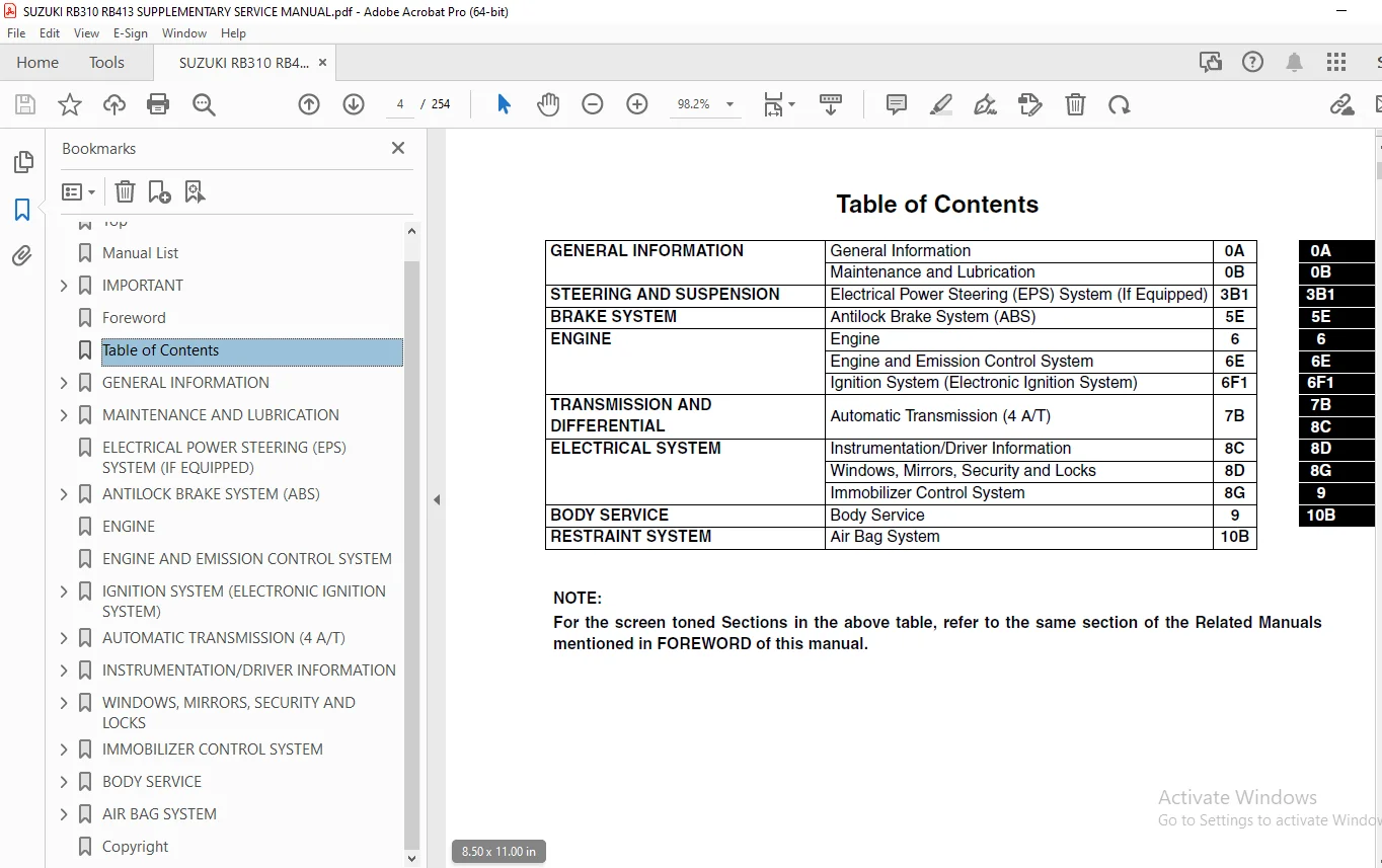
TABLE OF CONTENTS:
SUZUKI RB310 RB413 SUPPLEMENTARY SERVICE MANUAL – PDF DOWNLOAD
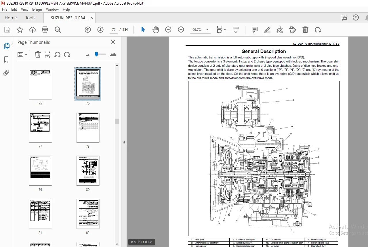
Top.............................................................................................................  0
Manual List.....................................................................................................  0
IMPORTANT.......................................................................................................  1
	WARNING/CAUTION/NOTE........................................................................................  1
Foreword........................................................................................................  2
Table of Contents...............................................................................................  4
GENERAL INFORMATION.............................................................................................  6
	Precautions.................................................................................................  7
		Precaution for Vehicles Equipped with a Supplemental Restraint (Air Bag) System.........................  7
			Diagnosis...........................................................................................  7
			Servicing and handling..............................................................................  8
	Warning, Caution and Information Labels..................................................................... 11
MAINTENANCE AND LUBRICATION..................................................................................... 12
	Maintenance Schedule........................................................................................ 13
		Maintenance Recommended under Severe Driving Conditions................................................. 13
ELECTRICAL POWER STEERING (EPS) SYSTEM (IF EQUIPPED)............................................................ 16
ANTILOCK BRAKE SYSTEM (ABS)..................................................................................... 18
	General Description......................................................................................... 20
		Components and Parts Location........................................................................... 20
		System Schematic........................................................................................ 21
		ABS Hydraulic Unit/Control Module Assembly.............................................................. 22
			Self-diagnosis function............................................................................. 22
			Fail-safe function.................................................................................. 22
		System Circuit.......................................................................................... 23
	Diagnosis................................................................................................... 25
		Precaution in Diagnosing Troubles....................................................................... 25
		ABS Diagnostic Flow Table............................................................................... 26
		ABS Warning Lamp Check.................................................................................. 29
		EBD Warning Lamp (Brake Warning Lamp) Check............................................................. 29
		Table – A ABS Warning Lamp Circuit Check – Lamp Does Not Come “ON” at Ignition Switch ON................ 30
		Table – B ABS Warning Lamp Circuit Check – Lamp Comes “ON” Steady....................................... 31
		Table – C ABS Warning Lamp Circuit Check – The Lamp Flashes Continuously While Ignition Switch is ON.... 32
		Table – D EBD Warning Lamp (Brake Warning Lamp) Check – Lamp Comes “ON” Steady.......................... 33
		Diagnostic Trouble Code (DTC) Check (Using SUZUKI Scan Tool)............................................ 34
		Diagnostic Trouble Code (DTC) Clearance................................................................. 34
		Serial Data Link Circuit Check.......................................................................... 35
		Diagnostic Trouble Code (DTC) Table..................................................................... 37
		DTC C1013 – Incorrect ABS Control Module Installed...................................................... 38
		DTC C1015 – G Sensor Circuit............................................................................ 38
		DTC C1021, DTC C1022 – Right-Front Wheel Speed Sensor Circuit or Sensor Ring............................ 40
		DTC C1025, DTC C1026 – Left-Front Wheel Speed Sensor Circuit or Sensor Ring............................. 40
		DTC C1031, DTC C1032 – Right-Rear Wheel Speed Sensor Circuit or Sensor Ring............................. 40
		DTC C1035, DTC C1036 – Left-Rear Wheel Speed Sensor Circuit or Sensor Ring.............................. 40
		DTC C1041 – Right-Front Inlet Solenoid Circuit.......................................................... 43
		DTC C1045 – Left-Front Inlet Solenoid Circuit........................................................... 43
		DTC C1051 – Right-Rear Inlet Solenoid Circuit........................................................... 43
		DTC C1055 – Left-Rear Inlet Solenoid Circuit............................................................ 43
		DTC C1042 – Right-Front Outlet Solenoid Circuit......................................................... 43
		DTC C1046 – Left-Front Outlet Solenoid Circuit.......................................................... 43
		DTC C1052 – Right-Rear Outlet Solenoid Circuit.......................................................... 43
		DTC C1056 – Left-Rear Outlet Solenoid Circuit........................................................... 43
		DTC C1057 – Power Source Circuit........................................................................ 44
		DTC C1061 – ABS Pump Motor Circuit...................................................................... 45
		DTC C1063 – ABS Fail-Safe Relay Circuit................................................................. 46
		DTC C1071 – ABS Control Module.......................................................................... 47
	On-Vehicle Service.......................................................................................... 48
		Precautions............................................................................................. 48
		ABS Hydraulic Unit Operation Check (Using SUZUKI Scan Tool)............................................. 48
		ABS Hydraulic Unit/Control Module Assembly.............................................................. 49
		Front Wheel Speed Sensor................................................................................ 51
		Front Wheel Speed Sensor Ring........................................................................... 53
		Rear Wheel Speed Sensor................................................................................. 54
		Rear Wheel Speed Sensor Ring (For 2WD vehicle).......................................................... 56
		Rear Wheel Speed Sensor Ring (For 4WD vehicle).......................................................... 56
		G Sensor (For 4WD Vehicle Only)......................................................................... 57
	Special Tool................................................................................................ 58
ENGINE.......................................................................................................... 60
ENGINE AND EMISSION CONTROL SYSTEM.............................................................................. 62
IGNITION SYSTEM (ELECTRONIC IGNITION SYSTEM).................................................................... 64
	General description......................................................................................... 65
	Diagnosis................................................................................................... 66
	On-vehicle service.......................................................................................... 68
		Ignition spark test..................................................................................... 68
		High-tension cords...................................................................................... 68
		Spark plugs............................................................................................. 69
		Ignition coil assembly (including ignitor).............................................................. 70
		Crankshaft position sensor (CKP sensor)................................................................. 70
		Ignition timing......................................................................................... 70
	Special tools............................................................................................... 72
AUTOMATIC TRANSMISSION (4 A/T).................................................................................. 74
	General Description......................................................................................... 76
		Specifications.......................................................................................... 77
		Functions............................................................................................... 78
		Table of Component Operation............................................................................ 78
		Electronic Shift Control System......................................................................... 79
			Transmission control module (TCM)................................................................... 80
			Fail safe function.................................................................................. 81
			Operation of shift solenoid valves and TCC solenoid valve........................................... 83
			Automatic gear shift diagram........................................................................ 84
	Diagnosis................................................................................................... 85
		Automatic Transmission Diagnostic Flow Table............................................................ 85
		Trouble Diagnosis Table................................................................................. 90
			Trouble diagnosis table-1........................................................................... 90
			Trouble diagnosis table-2........................................................................... 91
			Stall test.......................................................................................... 92
			Time lag test....................................................................................... 93
			Line pressure test.................................................................................. 94
			Engine brake test................................................................................... 95
			“P” range test...................................................................................... 95
		Electronic Control System Diagnosis..................................................................... 96
			Precautions in diagnosing troubles.................................................................. 96
			DTC check........................................................................................... 97
			DTC clearance....................................................................................... 97
			DTC table........................................................................................... 98
			TCM power and ground circuit check.................................................................. 99
			DTC P0715 Input/turbine speed sensor circuit malfunction............................................100
			DTC P0730 Incorrect gear ratio......................................................................102
			DTC P0753 Shift solenoid-A (No.1) electrical........................................................104
			DTC P0758 Shift solenoid-B (No.2) electrical........................................................104
			DTC P0743 TCC (lock-up) system electrical...........................................................104
			DTC P0741 TCC (lock-up) solenoid performance or stuck OFF...........................................106
			DTC P0720 Output shaft speed sensor circuit malfunction.............................................107
			DTC P1700 Throttle position signal input malfunction................................................110
			DTC P0705 Transmission range sensor (switch) circuit malfunction....................................112
			DTC P0725 Engine speed input circuit malfunction....................................................114
			DTC P0710 Transmission fluid temperature sensor circuit malfunction.................................116
			DTC P0763 Shift solenoid-C (No.3) electrical........................................................118
			DTC P0768 Shift solenoid-D (No.4) electrical........................................................118
			DTC P0773 Shift solenoid-E (No.5) electrical........................................................118
			DTC P1709 Engine coolant temperature/barometric pressure signal circuit.............................120
			DTC P0702/P1702 Transmission control system electrical or internal malfunction of TCM...............121
			Inspection of TCM and ITS circuits..................................................................122
	On-Vehicle Service..........................................................................................124
		Maintenance Service.....................................................................................124
			Fluid level at normal operating temperature.........................................................124
			Fluid level at room temperature.....................................................................125
			Fluid change........................................................................................125
		Transmission Control Module (TCM).......................................................................126
			Learning control initialization.....................................................................128
	Tightening Torque Specification.............................................................................129
	Special Tool................................................................................................130
	Required Service Material...................................................................................132
INSTRUMENTATION/DRIVER INFORMATION..............................................................................134
	General Description.........................................................................................135
		Combination Meter.......................................................................................135
	Diagnosis...................................................................................................136
		Low Fuel Warning Lamp...................................................................................136
	On-Vehicle Service..........................................................................................136
		Low Fuel Warning System.................................................................................136
WINDOWS, MIRRORS, SECURITY AND LOCKS............................................................................138
	Diagnosis...................................................................................................139
		Power Door Lock System (If Equipped)....................................................................139
		Keyless Entry System (If Equipped)......................................................................139
	On-Vehicle Service..........................................................................................140
		Power Door Lock System (If Equipped)....................................................................140
			Power door lock system component location...........................................................140
			Power door lock system operation inspection.........................................................140
			Power door lock system circuit inspection...........................................................141
			Power door lock system circuit check................................................................142
		Keyless Entry System (If Equipped)......................................................................143
			Keyless entry system operation inspection...........................................................143
			Keyless entry system circuit inspection.............................................................143
			Keyless entry system circuit check..................................................................144
			Transmitter.........................................................................................145
IMMOBILIZER CONTROL SYSTEM......................................................................................146
	On-Vehicle Service..........................................................................................147
		Registration Procedure of Immobilizer System Components.................................................147
			How to register ignition key........................................................................147
			Procedure after immobilizer control module replacement..............................................148
			Procedure after ECM replacement.....................................................................148
	Special Tools...............................................................................................149
BODY SERVICE....................................................................................................150
	Seats.......................................................................................................151
		Front Seat..............................................................................................151
		Rear Seat...............................................................................................153
AIR BAG SYSTEM..................................................................................................154
	General Description.........................................................................................156
		System Components and Wiring Location View and Connectors...............................................157
		System Wiring Diagram...................................................................................158
	Diagnosis...................................................................................................159
		Diagnostic Trouble Code (DTC)...........................................................................159
		Use of Special Tool.....................................................................................160
		Intermittents and Poor Connections......................................................................162
		Air Bag Diagnostic System Check.........................................................................163
		Air Bag Diagnostic System Check Flow Table..............................................................164
		DTC Check...............................................................................................165
		DTC Clearance...........................................................................................165
		DTC Table...............................................................................................166
		“AIR BAG” Warning Lamp Comes ON Steady..................................................................168
		“AIR BAG” Warning Lamp Does Not Come ON.................................................................168
		“AIR BAG” Warning Lamp Flashes..........................................................................168
		SDM Cannot Communicate through the Serial Data Circuit..................................................172
		DTC B1015 – Passenger Air Bag Initiator Circuit Resistance High.........................................175
		DTC B1016 – Passenger Air Bag Initiator Circuit Resistance Low..........................................175
		DTC B1018 – Passenger Air Bag Initiator Circuit Short to Ground.........................................175
		DTC B1019 – Passenger Air Bag Initiator Circuit Short to Power Circuit..................................175
		DTC B1021 – Driver Air Bag Initiator Circuit Resistance High............................................180
		DTC B1022 – Driver Air Bag Initiator Circuit Resistance Low.............................................180
		DTC B1024 – Driver Air Bag Initiator Circuit Short to Ground............................................180
		DTC B1025 – Driver Air Bag Initiator Circuit Short to Power Circuit.....................................180
		DTC B1031 – Power Source Voltage High...................................................................186
		DTC B1032 – Power Source Voltage Low....................................................................186
		DTC B1041 – Driver Pretensioner Initiator Circuit Resistance High.......................................189
		DTC B1042 – Driver Pretensioner Initiator Circuit Resistance Low........................................189
		DTC B1043 – Driver Pretensioner Initiator Circuit Short to Ground.......................................189
		DTC B1044 – Driver Pretensioner Initiator Circuit Short to Power Circuit................................189
		DTC B1045 – Passenger Pretensioner Initiator Circuit Resistance High....................................189
		DTC B1046 – Passenger Pretensioner Initiator Circuit Resistance Low.....................................189
		DTC B1047 – Passenger Pretensioner Initiator Circuit Short to Ground....................................189
		DTC B1048 – Passenger Pretensioner Initiator Circuit Short to Power Circuit.............................189
		DTC B1051 – Frontal Crash Detected (System Activation Command Outputted)................................196
		DTC B1056 – Sideward Crash (Driver Side) Detected (Side Air Bag System Activation Command Outputted)....197
		DTC B1057 – Sideward Crash (Passenger Side) Detected (Side Air Bag System Activation Command Outp.......197
		DTC B1058 – Frontal Crash Detected (Pretensioner Activation Command Outputted)..........................198
		DTC B1061 – “AIR BAG” Warning Lamp Circuit Failure......................................................199
		DTC B1063 – Side Sensor (Driver Side) Circuit Short to Ground...........................................201
		DTC B1064 – Side Sensor (Driver Side) Circuit Short to Power Circuit Or Open............................201
		DTC B1065 – Side Sensor (Passenger Side) Circuit Short to Ground........................................201
		DTC B1066 – Side Sensor (Passenger Side) Circuit Short to Power Circuit or Open.........................201
		DTC B1071 – Internal SDM Fault..........................................................................205
		DTC B1072 – Internal Side Sensor (Driver Side) Fault....................................................205
		DTC B1074 – Internal Side Sensor (Passenger Side) Fault.................................................205
		DTC B1073 – Side Sensor (Driver Side) Correspondence Abnormality........................................206
		DTC B1075 – Side Sensor (Passenger Side) Correspondence Abnormality.....................................206
		DTC B1081 – Side Air Bag (Driver Side) Intiator Circuit Resistance High.................................210
		DTC B1082 – Side Air Bag (Driver Side) Intiator Circuit Resistance Low..................................210
		DTC B1083 – Side Air Bag (Driver Side) Intiator Circuit Short to Ground.................................210
		DTC B1084 – Side Air Bag (Driver Side) Intiator Circuit Short to Power Circuit..........................210
		DTC B1085 – Side Air Bag (Passenger Side) Intiator Circuit Resistance High..............................210
		DTC B1086 – Side Air Bag (Passenger Side) Intiator Circuit Resistance Low...............................210
		DTC B1087 – Side Air Bag (Passenger Side) Intiator Circuit Short to Ground..............................210
		DTC B1088 – Side Air Bag (Passenger Side) Intiator Circuit Short to Power Circuit.......................210
	On-Vehicle Service..........................................................................................217
		Service Precautions.....................................................................................217
			Service and diagnosis...............................................................................217
			Disabling air bag system............................................................................218
			Enabling air bag system.............................................................................219
			Handling and storage................................................................................220
		Repairs and Inspections Required after an Accident......................................................226
			Accident with deployment/activation - component replacement.........................................226
			Accident with or without deployment/activation - component inspections..............................226
		SDM.....................................................................................................229
		Side Sensor (if equipped)...............................................................................230
		Seat Belt Pretensioner..................................................................................232
		Passenger Air Bag (Inflator) Module (if equipped).......................................................233
		Side Air Bag (Inflator) Module (If Equipped)............................................................235
		Driver Air Bag (Inflator) Module........................................................................235
		Contact Coil and Combination Switch Assembly............................................................235
		Seat Belt Pretensioner..................................................................................235
	Air Bag (Inflator) Module and Seat Belt Pretensioner Disposal...............................................236
		Deployment/Activation Outside of Vehicle................................................................236
		Deployment/Activation Inside of Vehicle.................................................................244
		Deployed Air Bag (Inflator) Module and Activated Seat Belt Pretensioner Disposal........................250
	Tightening Torque Specification.............................................................................251
	Special Tool................................................................................................251
Copyright.......................................................................................................254
S.S