Trusted Business
Verified & Licensed
Virus Free Files
100% Safe Downloads
Secure Payment
SSL Protected
Instant Delivery
Available Immediately
SUZUKI RG413 IGNIS SUPPLEMENTARY SERVICE MANUAL – PDF DOWNLOAD
$19.95
SUZUKI RG413 IGNIS SUPPLEMENTARY SERVICE MANUAL – PDF DOWNLOAD
Instant PDF Download
Available immediately
Save to Your Device
Download & keep forever
Antivirus Scanned
100% virus-free
Trusted Worldwide
175,000+ customers
Description
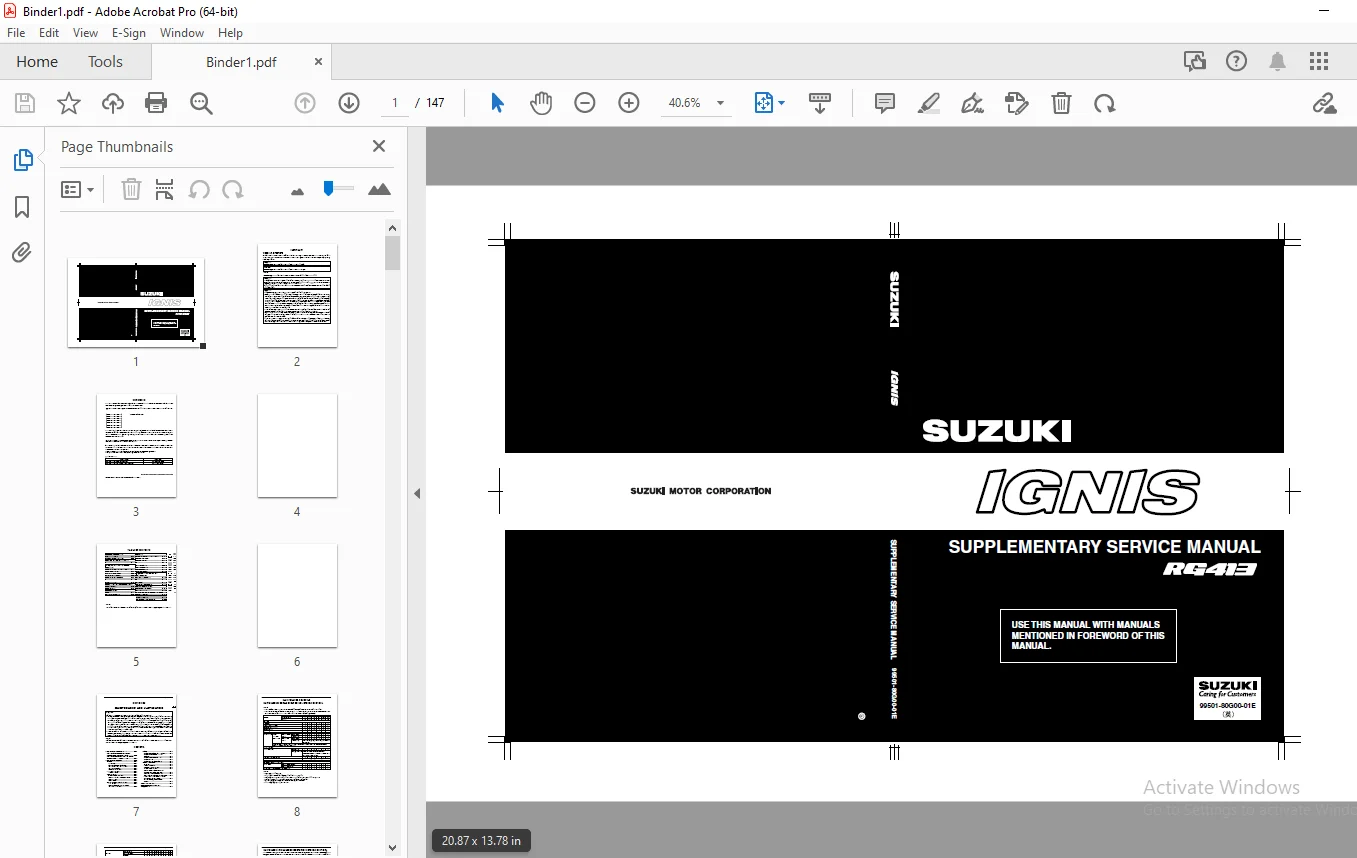
SUZUKI RG413 IGNIS SUPPLEMENTARY SERVICE MANUAL – PDF DOWNLOAD
FILE DETAILS:
SUZUKI RG413 IGNIS SUPPLEMENTARY SERVICE MANUAL – PDF DOWNLOAD
Language : English
Pages : 147
Downloadable : Yes
File Type : PDF
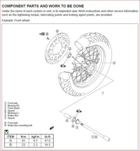
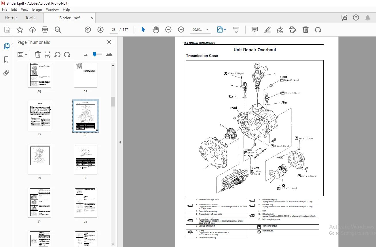
IMAGES PREVIEW OF THE MANUAL:
DESCRIPTION:
SUZUKI RG413 IGNIS SUPPLEMENTARY SERVICE MANUAL – PDF DOWNLOAD
- This SUPPLEMENTARY SERVICE MANUAL is a supplement to IGNIS (RG413) SERVICE MANUAL. It has been prepared exclusively for the following applicable model.
Applicable model: IGNIS (RG413) vehicles on and after following vehicle identification numbers (VINs). - This supplementary service manual describes only different service information of the above applicable model as compared with IGINIS SERVICE MANUAL. Therefore, whenever servicing the above applicable model, consult this supplement first. And for any section, item or description not found in this supplement, refer to the related service manual below.
- When replacing parts or servicing by disassembling, it is recommended to use SUZUKI genuine parts, tools and service materials as specified in each description.
- All information, illustrations and specifications contained in this literature are based on the latest product information available at the time of publication approval. And used as the main subject of description is the vehicle of standard specifications among others.
- Therefore, note that illustrations may differ from the vehicle being actually serviced.
- The right is reserved to make changes at any time without notice.
TABLE OF CONTENTS:
SUZUKI RG413 IGNIS SUPPLEMENTARY SERVICE MANUAL – PDF DOWNLOAD
Bookcove........................................................................................  1
99501_80G00_01E.................................................................................  2
	TOP.........................................................................................  0
	MANUAL LIST.................................................................................  0
	IMPORTANT...................................................................................  2
		WARNING/CAUTION/NOTE....................................................................  2
	FOREWORD....................................................................................  3
	TABLE OF CONTENTS...........................................................................  5
	SECTION 0B..................................................................................  7
		MAINTENANCE SCHEDULE....................................................................  8
			MAINTENANCE SCHEDULE UNDER NORMAL DRIVING CONDITIONS................................  8
			MAINTENANCE RECOMMENDED UNDER SEVERE DRIVING CONDITIONS............................. 10
	SECTION 3C.................................................................................. 11
		ON-VEHICLE SERVICE...................................................................... 12
			Driver Air Bag (Inflator) Module.................................................... 12
	SECTION 4B.................................................................................. 15
		General Description..................................................................... 15
		Diagnosis............................................................................... 15
			Diagnosis Table..................................................................... 15
			Propeller Shaft Joint Check......................................................... 16
		On-Vehicle Service...................................................................... 16
		Tightening Torque Specification......................................................... 20
		Required Service Material............................................................... 20
	SECTION 6A1................................................................................. 21
		On-Vehicle Service...................................................................... 22
			Timing Chain and Chain Tensioner.................................................... 22
	SECTION 7A.................................................................................. 27
		Unit Repair Overhaul.................................................................... 28
			Trasmission Case.................................................................... 28
			Gear Shifter and Differential....................................................... 29
			Unit Disassembly.................................................................... 31
				Fifth gears..................................................................... 31
			Unit Assembly....................................................................... 32
				Fifth gears..................................................................... 32
		Tightening Torque Specification......................................................... 35
	SECTION 7F.................................................................................. 37
		General Description..................................................................... 38
		Diagnosis............................................................................... 39
		On-Vehicle Service...................................................................... 40
			Oil Change.......................................................................... 40
			Differential Unit................................................................... 41
		Unit Repair Overhaul.................................................................... 43
		Tightening Torque Specification......................................................... 55
		Required Service Material............................................................... 55
		Special Tool............................................................................ 56
	SECTION 8................................................................................... 59
		Diagnosis............................................................................... 61
			Turn Signal and Hazard Warning Lights............................................... 61
			Power Door Lock System (If Equipped)................................................ 61
			Power Door Lock System with Keyless Entry System (If Equipped)...................... 61
			Door Mirror Heater (If Equipped).................................................... 62
		On-Vehicle Service...................................................................... 63
			Turn Signal and Hazard Warning Lights System........................................ 63
				Turn signal and hazard warning lights system circuit inspection................. 63
			Stop Lamp (Brake) Switch............................................................ 64
			Power Door Lock System (If Equipped)................................................ 65
				Power door lock system component location....................................... 65
				Power door lock system operation inspection..................................... 65
				Power door lock system circuit inspection....................................... 66
			Power Door Lock System with Keyless Entry System (If Equipped)...................... 67
				Power door lock system with keyless entry system component location............. 67
				System description.............................................................. 67
				Change of signal mode........................................................... 68
				Keyless entry system operation inspection....................................... 68
				Keyless entry system circuit inspection......................................... 69
				Transmitter..................................................................... 70
			Door Mirror Heater (If Equipped).................................................... 71
				Mirror heater switch............................................................ 71
				Mirror heater................................................................... 71
	SECTION 10B................................................................................. 73
		General Description..................................................................... 75
			System Components and Wiring Location View and Connectors........................... 76
			System Wiring Diagram............................................................... 77
		Diagnosis............................................................................... 78
			Diagnostic Trouble Code (DTC)....................................................... 78
			Use of Special Tool................................................................. 78
			Intermittents and Poor Connections.................................................. 80
			Air Bag Diagnostic System Check..................................................... 81
			Air Bag Diagnostic System Check Flow Table.......................................... 82
			DTC Check........................................................................... 83
			DTC Clearance....................................................................... 84
			DTC Table........................................................................... 85
			“AIR BAG” Warning Lamp Circuit Trouble Diagnosis Table.............................. 87
				“AIR BAG” warning lamp comes on steady without flashing......................... 88
				“AIR BAG” warning lamp does not come on......................................... 89
				“AIR BAG” warning lamp flashes.................................................. 91
				“AIR BAG” warning lamp can not indicate flashing................................ 92
			SDM Serial Data Circuit Trouble Diagnosis Table..................................... 93
			DTC B1015 – Passenger Air Bag Initiator Circuit Resistance High..................... 95
			DTC B1016 – Passenger Air Bag Initiator Circuit Resistance Low...................... 95
			DTC B1018 – Passenger Air Bag Initiator Circuit Short to Ground..................... 95
			DTC B1019 – Passenger Air Bag Initiator Circuit Short to Power Circuit.............. 95
			DTC B1021 – Driver Air Bag Initiator Circuit Resistance High........................100
			DTC B1022 – Driver Air Bag Initiator Circuit Resistance Low.........................100
			DTC B1024 – Driver Air Bag Initiator Circuit Short to Ground........................100
			DTC B1025 – Driver Air Bag Initiator Circuit Short to Power Circuit.................100
			DTC B1032 – Power Source Voltage Low................................................106
			DTC B1041 – Driver Pretensioner Initiator Circuit Resistance High...................109
			DTC B1042 – Driver Pretensioner Initiator Circuit Resistance Low....................109
			DTC B1043 – Driver Pretensioner Initiator Circuit Short to Ground...................109
			DTC B1044 – Driver Pretensioner Initiator Circuit Short to Power Circuit............109
			DTC B1045 – Passenger Pretensioner Initiator Circuit Resistance High................109
			DTC B1046 – Passenger Pretensioner Initiator Circuit Resistance Low.................109
			DTC B1047 – Passenger Pretensioner Initiator Circuit Short to Ground................109
			DTC B1048 – Passenger Pretensioner Initiator Circuit Short to Power Circuit.........109
			DTC B1051 – Frontal Crash Detected (System Activation Command Outputted)............115
			DTC B1071 – Internal SDM Fault......................................................116
			DTC B1013 – System Specifications Different from SDM Specifications.................116
		On-Vehicle Service......................................................................117
			Service Precautions.................................................................117
				Service and diagnosis...........................................................117
				Disabling air bag system........................................................118
				Enabling air bag system.........................................................118
				Handling and storage............................................................119
			Repairs and Inspections Required after an Accident..................................124
			Accident with Deployment/Activation – Component Replacement.........................124
			Accident with or without Deployment/Activation – Component Inspections..............124
			SDM.................................................................................127
			Driver Air Bag (Inflator) Module....................................................130
			Contact Coil and Combination Switch Assembly........................................130
			Seat Belt Pretensioner..............................................................130
		Air Bag (Inflator) Module and Seat Belt Pretensioner Disposal...........................131
			Deployment/Activation Outside of Vehicle............................................132
			Deployment/Activation Inside Vehicle................................................139
			Deployed Air Bag (Inflator) Module and Activated Seat Belt Pretensioner Disposal....143
		Tightening Torque Specification.........................................................144
		Special Tool............................................................................144
	COPYRIGHT...................................................................................147
	BOOKCOVER...................................................................................  0
S.S