Trusted Business
Verified & Licensed
Virus Free Files
100% Safe Downloads
Secure Payment
SSL Protected
Instant Delivery
Available Immediately
SUZUKI RH413 RH416 FOR AUTOMATIC AIR CONDITIONING SYSTEM LIANA SUPPLEMENTARY SERVICE MANUAL – PDF DOWNLOAD
$19.95
Instant PDF Download
Available immediately
Save to Your Device
Download & keep forever
Antivirus Scanned
100% virus-free
Trusted Worldwide
175,000+ customers
Description
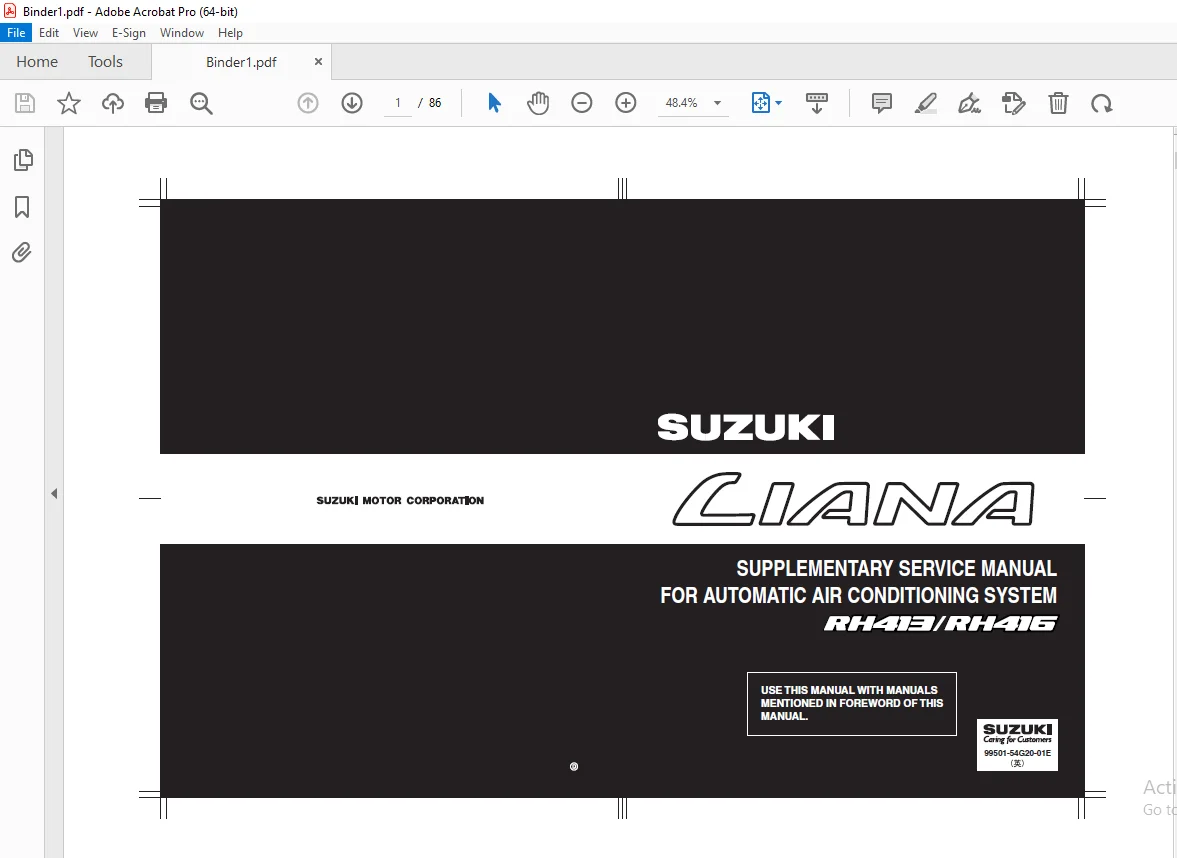
SUZUKI RH413 RH416 FOR AUTOMATIC AIR CONDITIONING SYSTEM LIANA SUPPLEMENTARY SERVICE MANUAL – PDF DOWNLOAD
FILE DETAILS:
SUZUKI RH413 RH416 FOR AUTOMATIC AIR CONDITIONING SYSTEM LIANA SUPPLEMENTARY SERVICE MANUAL – PDF DOWNLOAD
Language : English
Pages : 86
Downloadable : Yes
File Type : PDF
IMAGES PREVIEW OF THE MANUAL:
TABLE OF CONTENTS:
SUZUKI RH413 RH416 FOR AUTOMATIC AIR CONDITIONING SYSTEM LIANA SUPPLEMENTARY SERVICE MANUAL – PDF DOWNLOAD
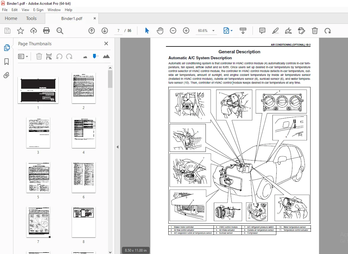
Bookcover.................................................................................................... 1
99501_54G20_01E.............................................................................................. 2
	Manual List.............................................................................................. 0
	IMPORTANT................................................................................................ 2
		WARNING/CAUTION/NOTE................................................................................. 2
	FOREWORD................................................................................................. 3
	TABLE OF CONTENTS........................................................................................ 4
	SECTION 1B............................................................................................... 5
		General Description.................................................................................. 7
			Automatic A/C System Description................................................................. 7
			Automatic A/C System Wiring Diagram.............................................................. 9
		General Diagnosis....................................................................................10
			General Diagnosis Table..........................................................................10
			Performance Diagnosis............................................................................14
		Electrical Diagnosis.................................................................................16
			HVAC Control Module and its Circuits.............................................................16
				HVAC control module voltage table............................................................16
		HVAC Diagnosis.......................................................................................19
			On-Board Diagnostic System.......................................................................19
			Precautions in Diagnosing Trouble................................................................19
			Air Conditioning System Diagnostic Flow Table....................................................20
				Customer complaint analysis..................................................................21
				Visual inspection............................................................................21
				DTC check....................................................................................21
				Troubleshooting malfunction..................................................................21
				A/C system symptom diagnosis.................................................................21
				Check for intermittent problem...............................................................21
				Final confirmation test......................................................................21
			Visual Inspection................................................................................22
			A/C Switch Indicator Lamp and Air Intake Switch Indicator Lamp Check.............................22
			DTC Check........................................................................................23
				Using SUZUKI scan tool.......................................................................23
				Not using SUZUKI scan tool...................................................................23
			DTC Clearance....................................................................................24
				Using SUZUKI scan tool.......................................................................24
				Not using SUZUKI scan tool...................................................................25
			DTC Table........................................................................................26
			Fail-Safe Table..................................................................................28
			Scan Tool Data...................................................................................29
				Scan tool data definitions...................................................................30
			DTC B1501 (No.01): Outside Air Temperature Sensor and its Circuit Malfunction....................31
			DTC B1502 (No.02): Inside Air Temperature Sensor and its Circuit Malfunction.....................32
			DTC B1503 (No.03): A/C Evaporator Temperature Sensor and its Circuit Malfunction.................33
			DTC B1504 (No.04): Sunload Sensor and its Circuit Malfunction....................................35
			DTC B1510 (No.10): Water Temperature Sensor and its Circuit Malfunction..........................36
			DTC B1511 (No.11): Temperature Control Actuator (Position Sensor) and its Circuit Malfunction....38
			DTC B1512 (No.12): Air Flow Control Actuator (Position Sensor) and its Circuit Malfunction.......40
			DTC B1513 (No.13): Temperature Control Actuator and its Circuit Malfunction......................41
			DTC B1514 (No.14): Air Flow Control Actuator and its Circuit Malfunction.........................43
			DTC B1520 (No.20): Temperature Selector and its Circuit Malfunction..............................45
			DTC B1521(No.21): Blower Speed Selector and Its Circuit..........................................46
			DTC B1522 (No.22): Air Flow Selector and Its Circuit Malfunction.................................46
		On-Vehicle Service...................................................................................47
			HVAC Control Module..............................................................................47
			HVAC Control Module (Panel Unit / Board Unit)....................................................48
			Panel Unit (HVAC Control Module) Inspection......................................................48
			Water Temperature Sensor.........................................................................50
			Sunload Sensor...................................................................................51
			Outside Air Temperature Sensor...................................................................52
			Blower Motor Controller..........................................................................53
			Temperature Control Actuator.....................................................................54
			Air Flow Control Actuator........................................................................56
			Actuator Linkage.................................................................................58
			Heater and Cooling Unit..........................................................................58
			A/C Evaporator Outlet Air Temperature Sensor.....................................................59
			A/C Refrigerant Pressure Switch..................................................................60
		Special Tool.........................................................................................62
	SECTION 8A...............................................................................................63
		Connector layout diagram.............................................................................65
			Engine compartment...............................................................................65
				E: Main harness..............................................................................65
				E: Main harness..............................................................................67
			Instrument panel.................................................................................69
				E: Main harness..............................................................................69
				E: Main harness..............................................................................71
				G: Instrument panel harness..................................................................73
				G: Instrument panel harness..................................................................76
		System circuit diagram...............................................................................79
			A-5 Engine & A/C control System..................................................................79
			E-2 Auto A/C system..............................................................................83
		Connector list.......................................................................................85
			E Connector......................................................................................85
			G Connector......................................................................................85
	Copyright................................................................................................86
S.S