Trusted Business
Verified & Licensed
Virus Free Files
100% Safe Downloads
Secure Payment
SSL Protected
Instant Delivery
Available Immediately
SUZUKI RH413 RH416 LIANA SERVICE MANUAL – PDF DOWNLOAD
$34.95
Instant PDF Download
Available immediately
Save to Your Device
Download & keep forever
Antivirus Scanned
100% virus-free
Trusted Worldwide
175,000+ customers
Description
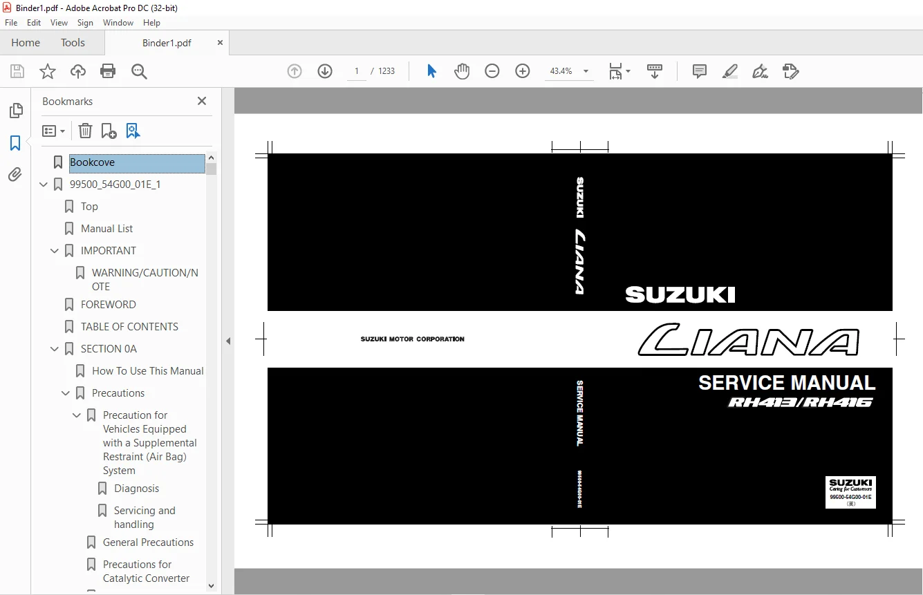
SUZUKI RH413 RH416 LIANA SERVICE MANUAL – PDF DOWNLOAD
FILE DETAILS:
SUZUKI RH413 RH416 LIANA SERVICE MANUAL – PDF DOWNLOAD
Language : English
Pages : 1233
Downloadable : Yes
File Type : PDF
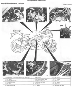
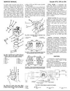
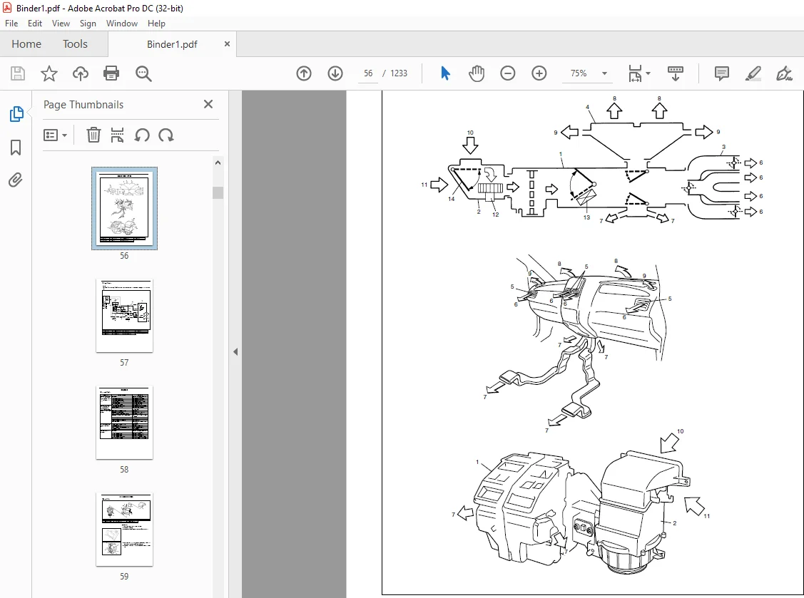
IMAGES PREVIEW OF THE MANUAL:
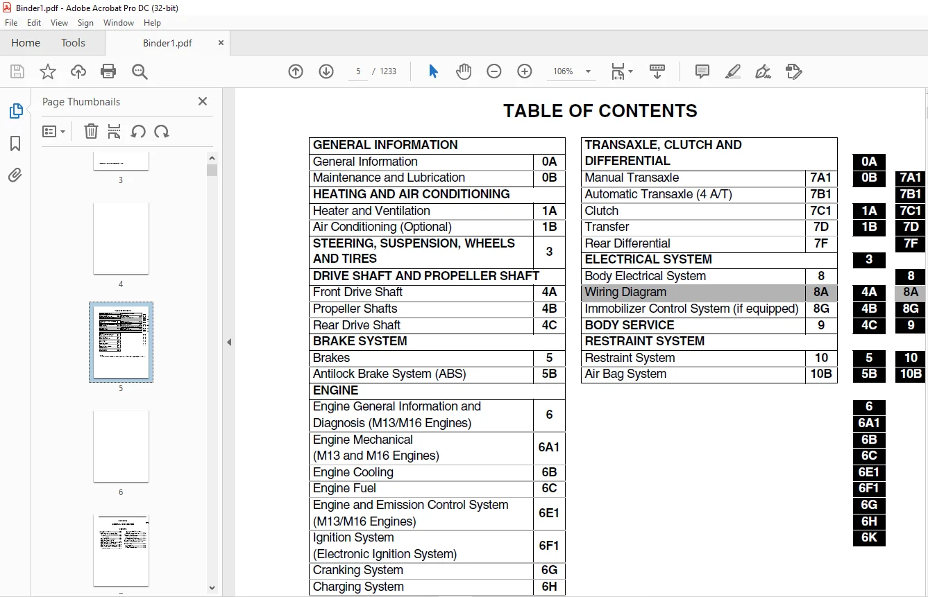
TABLE OF CONTENTS:
SUZUKI RH413 RH416 LIANA SERVICE MANUAL – PDF DOWNLOAD
Bookcove............................................................................................................   1
99500_54G00_01E_1...................................................................................................   2
	Top.............................................................................................................   0
	Manual List.....................................................................................................   0
	IMPORTANT.......................................................................................................   2
		WARNING/CAUTION/NOTE........................................................................................   2
	FOREWORD........................................................................................................   3
	TABLE OF CONTENTS...............................................................................................   5
	SECTION 0A......................................................................................................   7
		How To Use This Manual......................................................................................   8
		Precautions.................................................................................................   9
			Precaution for Vehicles Equipped with a Supplemental Restraint (Air Bag) System.........................   9
				Diagnosis...........................................................................................   9
				Servicing and handling..............................................................................  10
			General Precautions.....................................................................................  12
			Precautions for Catalytic Converter.....................................................................  15
			Precaution for Installing Mobile Communication Equipment................................................  15
			Precaution for Vehicle Tie-Down Hooks...................................................................  16
			Precaution in Servicing Full-Time 4WD Vehicle...........................................................  16
			Precautions for Electrical Circuit Service..............................................................  17
			Electrical Circuit Inspection Procedure.................................................................  20
				Open circuit check..................................................................................  20
				Short circuit check (wire harness to ground)........................................................  22
			Intermittent and Poor Connection........................................................................  23
		Identification Information..................................................................................  25
			Vehicle Identification Number...........................................................................  25
			Engine Identification Number............................................................................  25
			Transmission Identification Number......................................................................  25
		Warning, Caution and Information Labels.....................................................................  26
		Vehicle Lifting Points......................................................................................  27
		Abbreviations and Symbols May Be Used in This Manual........................................................  29
		Fastener Information........................................................................................  32
			Metric Fasteners........................................................................................  32
			Fastener Strength Identification........................................................................  32
			Standard Tightening Torque..............................................................................  32
	SECTION 0B......................................................................................................  35
		Maintenance Schedule........................................................................................  36
			Maintenance Schedule Under Normal Driving Conditions....................................................  36
			Maintenance Recommended under Severe Driving Conditions.................................................  38
		Maintenance Service.........................................................................................  39
			Engine..................................................................................................  39
				Drive belt..........................................................................................  39
				Valve lash (clearance)..............................................................................  40
				Engine oil and oil filter...........................................................................  40
				Engine coolant......................................................................................  42
				Exhaust system......................................................................................  42
			Ignition System.........................................................................................  42
				Spark plugs.........................................................................................  42
			Fuel System.............................................................................................  43
				Air cleaner filter..................................................................................  43
				Fuel lines and connections..........................................................................  43
				Fuel filter.........................................................................................  43
				Fuel tank...........................................................................................  44
			Emission Control System.................................................................................  44
				PCV valve...........................................................................................  44
				Fuel evaporative emission control system............................................................  44
			Brake...................................................................................................  44
				Brake discs and pads (front)........................................................................  44
				Brake drums and shoes (rear)........................................................................  45
				Brake hoses and pipes...............................................................................  45
				Brake fluid.........................................................................................  45
				Brake lever and cable...............................................................................  45
			Chassis and Body........................................................................................  46
				Clutch..............................................................................................  46
				Tires / Wheels......................................................................................  46
				Suspension system...................................................................................  47
				Steering system.....................................................................................  47
				Drive shaft (axle) boots / Propeller shafts (4WD)...................................................  48
				Manual transaxle oil................................................................................  49
				Automatic transaxle fluid...........................................................................  49
				Transfer oil (4WD A/T) and rear differential oil (4WD)..............................................  50
				All latches, hinges and locks.......................................................................  51
				Power steering (P/S) system (if equipped)...........................................................  51
			Final Inspection........................................................................................  52
		Recommended Fluids and Lubricants...........................................................................  54
	SECTION 1A......................................................................................................  55
		General Description.........................................................................................  56
			Wiring Circuit..........................................................................................  57
		Diagnosis...................................................................................................  58
			Diagnosis Table.........................................................................................  58
		On-Vehicle Service..........................................................................................  59
			Blower Unit.............................................................................................  59
			Blower Motor............................................................................................  60
			Blower Motor Resistor...................................................................................  61
			Heater Unit.............................................................................................  62
			Heater Controller.......................................................................................  63
			Air Inlet Actuator......................................................................................  65
			Blower Motor and Blower Motor High Relays...............................................................  66
			Center Ventilation Louver...............................................................................  67
			Side Ventilation Louver.................................................................................  67
	SECTION 1B......................................................................................................  69
		General Description.........................................................................................  71
			Sub-cool System.........................................................................................  71
			A/C Evaporator Inlet Air Temperature Sensor and A/C Evaporator Outlet Air Temperature Sensor............  72
			Refrigerant Type........................................................................................  72
			Major Components and Location...........................................................................  73
		Diagnosis...................................................................................................  74
			General Diagnosis Table.................................................................................  74
			Abnormal Noise Diagnosis................................................................................  76
			Quickly Checking of Refrigerant Charge..................................................................  78
			Performance Diagnosis...................................................................................  79
				Performance diagnosis table.........................................................................  81
				Detail diagnosis table (ambient temperature at 30°C (86°F)).........................................  82
		Electrical Diagnosis........................................................................................  83
			A/C System Inspection of ECM and Its Circuits...........................................................  83
				Wiring diagram......................................................................................  83
				Voltage check.......................................................................................  84
		Refrigerant Recovery, Evacuating and Charging...............................................................  86
			Operation Procedure for Refrigerant Charging............................................................  86
			Recovery................................................................................................  87
			Replenishing Compressor Oil.............................................................................  87
			Evacuating..............................................................................................  88
				Evacuating procedure................................................................................  88
				Checking system for pressure leaks..................................................................  89
			Charging................................................................................................  90
				Charging procedure..................................................................................  90
				Replacement of refrigerant container in charging procedure..........................................  91
			Leak Test...............................................................................................  92
				Liquid leak detectors...............................................................................  92
		On-vehicle Service..........................................................................................  93
			Service Precaution .....................................................................................  93
				Handling refrigerant HFC-134a (R-134a)..............................................................  93
			Refrigerant Line........................................................................................  93
			Condenser Assembly......................................................................................  94
			Desiccant...............................................................................................  96
			Condenser Cooling Fan...................................................................................  96
			Heater and Cooling Unit.................................................................................  98
			A/C Evaporator.......................................................................................... 100
			A/C Evaporator Inlet and Outlet Air Temperature Sensors................................................. 102
			Expansion Valve......................................................................................... 102
			A/C Refrigerant Pressure Switch......................................................................... 103
			A/C Switch and Defroster Switch in Heater Controller.................................................... 104
			Compressor Relay and Condenser Cooling Fan Relay........................................................ 104
			Compressor.............................................................................................. 105
			Compressor Drive Belt................................................................................... 105
			Magnet Clutch........................................................................................... 106
		Required Service Material................................................................................... 109
		Special Tool................................................................................................ 109
	SECTION 3....................................................................................................... 111
		CONTENTS.................................................................................................... 111
			Diagnosis............................................................................................... 113
				General Diagnosis................................................................................... 113
				Diagnosis Table..................................................................................... 113
			Specifications.......................................................................................... 117
			On-Vehicle Service...................................................................................... 118
				Front Wheel Alignment............................................................................... 118
					Preliminary checks prior to adjustment front wheel alignment.................................... 118
					Toe inspection and adjustment................................................................... 119
					Steering angle check and adjustment............................................................. 120
					Reference information........................................................................... 120
				Rear Wheel Alignment................................................................................ 121
					Toe inspection and adjustment................................................................... 121
					Reference information........................................................................... 121
			General Description..................................................................................... 123
				P/S System Description.............................................................................. 123
			Specifications.......................................................................................... 124
				Specification and Service Data...................................................................... 124
			Diagnosis............................................................................................... 125
				Diagnosis Table..................................................................................... 125
				Steering Wheel Play Check........................................................................... 126
				Steering Force Check................................................................................ 127
				Power Steering Fluid Level Check.................................................................... 127
				Power Steering Belt Check........................................................................... 127
				Power Steering Belt Tension Adjustment.............................................................. 128
				Idle Up System Check................................................................................ 128
				Fluid Leakage Check................................................................................. 129
				Hydraulic Pressure in P/S Circuit Check............................................................. 130
				Steering Rack Boot Check............................................................................ 131
				Tie Rod End Boot Check.............................................................................. 132
				Steering Shaft Joint Check.......................................................................... 132
				Air Bleeding Procedure.............................................................................. 132
			On-vehicle Service...................................................................................... 133
				Power Steering Belt................................................................................. 133
				Tie Rod End......................................................................................... 133
				Power Steering Gear Box............................................................................. 136
				Tie Rod/Rack Boot................................................................................... 139
				Power Steering Pump................................................................................. 141
			Tightening Torque Specification......................................................................... 148
			Required Service Material............................................................................... 149
			Special Tool............................................................................................ 149
			General Description..................................................................................... 150
				Steering Column..................................................................................... 150
				Steering Wheel and Driver Air Bag (Inflator) Module................................................. 151
			Diagnosis............................................................................................... 151
				Inspection and Repair Required after Accident....................................................... 151
			On-Vehicle Service...................................................................................... 152
				Service Precautions................................................................................. 152
					Service and diagnosis........................................................................... 152
					Disabling air bag system........................................................................ 152
					Enabling air bag system......................................................................... 152
					Handling and storage............................................................................ 153
					Disposal........................................................................................ 153
				Driver Air Bag (Inflator) Module.................................................................... 153
				Steering Wheel...................................................................................... 155
				Centering Contact Coil.............................................................................. 156
				Contact Coil and Combination Switch Assembly........................................................ 157
				Steering Column Assembly............................................................................ 159
				Steering Lock Assembly (Ignition Switch)............................................................ 164
				Steering Lower Shaft................................................................................ 165
			Checking Steering Column Assembly and Lower Shaft for Accident Damage................................... 167
			Special Tool............................................................................................ 167
			General Description..................................................................................... 168
				Construction........................................................................................ 168
			Diagnosis............................................................................................... 169
				Diagnosis Table..................................................................................... 169
				Stabilizer Bar and/or Bushing Check................................................................. 169
				Strut Assembly Check................................................................................ 169
				Suspension Control Arm/Steering Knuckle Check....................................................... 170
				Suspension Control Arm Bushing Check................................................................ 170
				Suspension Control Arm Joint Check.................................................................. 170
				Front Suspension Frame Check........................................................................ 171
				Front Suspension Fasteners Check.................................................................... 171
				Wheel Disc, Nut and Bearing Check................................................................... 171
			On-vehicle Service...................................................................................... 172
				Strut Assembly...................................................................................... 172
				Stabilizer Bar and/or Bushings...................................................................... 175
				Wheel Hub and Steering Knuckle...................................................................... 177
				Suspension Control Arm/Bushing...................................................................... 183
				Front Suspension Frame.............................................................................. 186
			Required Service Material............................................................................... 188
			Special Tool............................................................................................ 189
			General Description..................................................................................... 191
				Construction........................................................................................ 191
			Diagnosis............................................................................................... 192
				Strut Assembly Check................................................................................ 192
				Stabilizer Bar, Bushing and/or Joint Check.......................................................... 192
				Suspension Knuckle Check............................................................................ 193
				Control Rod Check................................................................................... 193
				Trailing Rod Check.................................................................................. 194
				Suspension Frame, Bushing and Pad Check............................................................. 194
				Rear Suspension Fasteners........................................................................... 194
				Wheel Disc, Nut and Bearing Check................................................................... 194
			On-vehicle Service...................................................................................... 195
				Rear Strut Assembly................................................................................. 195
				Stabilizer Bar and/or Bushings...................................................................... 199
				Control Rod......................................................................................... 201
				Trailing Rod........................................................................................ 203
				Suspension Frame.................................................................................... 204
				Wheel Hub, Wheel Bearing and Wheel Stud............................................................. 206
				Knuckle............................................................................................. 208
			Tightening Torque Specifications........................................................................ 211
			Required Service Material............................................................................... 211
			Special Tool............................................................................................ 212
			General Description..................................................................................... 214
				Construction........................................................................................ 214
			On-vehicle Service...................................................................................... 215
				Rear Suspension Frame............................................................................... 215
				Wheel Hub, Wheel Stud/Wheel Bearing Outside Inner Race.............................................. 217
				Knuckle, Wheel Bearing/Oil Seal..................................................................... 219
			Tightening Torque Specifications........................................................................ 220
			Required Service Material............................................................................... 221
			Special Tool............................................................................................ 221
			General Description..................................................................................... 222
				Tires............................................................................................... 222
					Tire placard.................................................................................... 222
					Inflation of tires.............................................................................. 222
					Matched tires and wheels (steel type)........................................................... 223
					Replacement tires............................................................................... 223
				Wheels.............................................................................................. 224
					Wheel maintenance............................................................................... 224
					Replacement wheels.............................................................................. 224
					How to measure wheel runout..................................................................... 224
					Metric lug nuts and wheel studs................................................................. 224
			Specifications.......................................................................................... 225
			Diagnosis............................................................................................... 225
				Diagnosis Table..................................................................................... 225
				Irregular and/or Premature Wear..................................................................... 225
				Wear Indicators..................................................................................... 226
				Radial Tire Waddle.................................................................................. 226
				Radial Tire Lead/Pull............................................................................... 227
				Balancing Wheels.................................................................................... 227
				General Balance Procedures.......................................................................... 228
			On-Vehicle Service...................................................................................... 229
				Wheel............................................................................................... 229
				Tire................................................................................................ 230
	SECTION 4A...................................................................................................... 231
		General Description......................................................................................... 232
			Component............................................................................................... 232
		Diagnosis................................................................................................... 232
			Diagnosis Table......................................................................................... 232
			Drive Shaft Boot Check.................................................................................. 232
		On-Vehicle Service.......................................................................................... 233
			Drive Shaft Assembly.................................................................................... 234
		Tightening Torque Specification............................................................................. 247
		Required Service Material................................................................................... 247
		Special Tool................................................................................................ 247
	SECTION 4B...................................................................................................... 249
		General Description......................................................................................... 249
		On-Vehicle Service.......................................................................................... 250
			Propeller Shafts........................................................................................ 250
		Tightening Torque Specification............................................................................. 251
	SECTION 4C...................................................................................................... 253
		General Description......................................................................................... 253
		On-Vehicle Service.......................................................................................... 253
		Tightening Torque Specifications............................................................................ 256
		Required Service Material................................................................................... 256
	SECTION 5....................................................................................................... 257
		General Description......................................................................................... 258
		Diagnosis................................................................................................... 260
			Road Testing Brakes..................................................................................... 260
			Brake Fluid Leaks....................................................................................... 260
			Substandard or Contaminated Brake Fluid................................................................. 260
			Diagnosis Table......................................................................................... 261
			Brake Pedal Free Height Inspection...................................................................... 264
			Brake Pedal Play Inspection............................................................................. 264
			Stop Light Switch Adjustment............................................................................ 264
			Excessive Pedal Travel Inspection....................................................................... 265
			Front Brake Pad Inspection.............................................................................. 265
			Brake Disc Inspection................................................................................... 265
			Parking Brake Inspection and Adjustment................................................................. 266
			Booster Operation Inspection............................................................................ 267
			Fluid Pressure Test (If Equipped with LSPV)............................................................. 268
			Master Cylinder and Brake Fluid Level Inspection........................................................ 270
			Brake Hose and Pipe Inspection.......................................................................... 271
		On-Vehicle Service.......................................................................................... 271
			Air Bleeding of Brake System............................................................................ 271
			Front Brake............................................................................................. 273
				Brake pad........................................................................................... 273
				Caliper assembly.................................................................................... 275
				Brake disc.......................................................................................... 279
			Rear Brake.............................................................................................. 281
				Brake drum.......................................................................................... 281
				Brake shoe.......................................................................................... 285
				Wheel cylinder...................................................................................... 286
				Brake back plate.................................................................................... 288
			Master Cylinder......................................................................................... 290
				Master cylinder reservoir........................................................................... 290
				Master cylinder assembly............................................................................ 291
			Brake Booster........................................................................................... 296
			Brake Hose/Pipe......................................................................................... 299
				Front brake hose/pipe............................................................................... 299
				Rear brake hose/pipe................................................................................ 301
				Parking brake cable................................................................................. 303
			LSPV (Load Sensing Proportioning Valve) Assembly (If Equipped).......................................... 305
		Required Service Material................................................................................... 307
		Special Tool................................................................................................ 308
	SECTION 5B...................................................................................................... 309
		General Description......................................................................................... 310
			Components/Parts Location and Brake Hose/Pipe Routing................................................... 310
			System Schematic........................................................................................ 312
			ABS Hydraulic Unit/Control Module Assembly.............................................................. 313
				Self-diagnosis function............................................................................. 313
				Fail-safe function.................................................................................. 313
			System Circuit.......................................................................................... 314
		Diagnosis................................................................................................... 316
			Precaution in Diagnosing Troubles....................................................................... 316
			ABS Diagnostic Flow Table............................................................................... 317
			ABS Warning Lamp Check.................................................................................. 320
			EBD Warning Lamp (Brake Warning Lamp) Check............................................................. 320
			Table-A ABS Warning Lamp Circuit Check – Lamp Does Not Come “ON” at Ignition Switch ON.................. 321
			Table-B ABS Warning Lamp Circuit Check – Lamp Comes “ON” Steady......................................... 322
			Table-C ABS Warning Lamp Circuit Check – The Lamp Flashes Continuously While Ignition Switch Is ON...... 323
			Table-D Code (DTC) Is Not Outputted Even with Diagnosis Switch Terminal Connected to Ground............. 324
			Table-E EBD Warning Lamp (Brake Warning Lamp) Check – Lamp Comes “On” Steady............................ 325
			Diagnostic Trouble Code (DTC) Check (Using ABS Warning Lamp)............................................ 326
			Diagnostic Trouble Code (DTC) Check..................................................................... 327
			(Using SUZUKI Scan Tool)................................................................................ 327
			Diagnostic Trouble Code (DTC) Clearance................................................................. 327
			Diagnostic Trouble Code (DTC) Table..................................................................... 328
			DTC C1013 (DTC 13) – System Specifications Different From ABS Control Module Specifications............. 330
			DTC C1015 (DTC 15) -G Sensor Circuit.................................................................... 330
			DTC C1021 (DTC 21), DTC C1022 (DTC 22) – Right-front Wheel Speed Sensor Circuit or Sensor Ring.......... 332
			DTC C1025 (DTC 25), DTC C1026 (DTC 26) – Left-front Wheel Speed Sensor Circuit or Sensor Ring........... 332
			DTC C1031 (DTC 31), DTC C1032 (DTC 32) – Right-rear Wheel Speed Sensor Circuit or Sensor Ring........... 332
			DTC C1035 (DTC 35), DTC C1036 (DTC 36) – Left-rear Wheel Speed Sensor Circuit or Sensor Ring............ 332
			DTC C1041 (DTC 41) – Right-front Inlet Solenoid Circuit................................................. 334
			DTC C1045 (DTC 45) – Left-front Inlet Solenoid Circuit.................................................. 334
			DTC C1051 (DTC 51) – Right-rear Inlet Solenoid Circuit.................................................. 334
			DTC C1055 (DTC 55) – Left-rear Inlet Solenoid Circuit................................................... 334
			DTC C1042 (DTC 42) – Right-front Outlet Solenoid Circuit................................................ 334
			DTC C1046 (DTC 46) – Left-front Outlet Solenoid Circuit................................................. 334
			DTC C1052 (DTC 52) – Right-rear Outlet Solenoid Circuit................................................. 334
			DTC C1056 (DTC 56) – Left-rear Outlet Solenoid Circuit.................................................. 334
			DTC C1057 (DTC 57) – Power Source Circuit............................................................... 335
			DTC C1061 (DTC 61) – ABS Pump Motor Circuit............................................................. 336
			DTC C1063 (DTC 63) – ABS Fail-safe Relay Circuit........................................................ 337
			DTC C1071 (DTC 71) – ABS Control Module................................................................. 338
		ON-Vehicle Service.......................................................................................... 339
			Precautions............................................................................................. 339
			ABS Hydraulic Unit Operation Check...................................................................... 339
			(Using SUZUKI Scan Tool)................................................................................ 339
			ABS Hydraulic Unit Operation Check...................................................................... 339
			(Not Using SUZUKI Scan Tool)............................................................................ 339
			ABS Hydraulic Unit/Control Module Assembly.............................................................. 341
			Front Wheel Speed Sensor................................................................................ 343
			Front Wheel Speed Sensor Ring........................................................................... 345
			Rear Wheel Speed Sensor................................................................................. 346
			Rear Wheel Speed Sensor Ring............................................................................ 349
			G Sensor (For 4WD Vehicle Only)......................................................................... 349
		Special Tool................................................................................................ 350
	SECTION 6....................................................................................................... 351
		General Information......................................................................................... 353
			Statement on Cleanliness and Care....................................................................... 353
			General Information on Engine Service................................................................... 353
				Precaution on fuel system service................................................................... 354
				Fuel pressure relief procedure...................................................................... 355
				Fuel leakage check procedure........................................................................ 355
		Engine Diagnosis............................................................................................ 355
			General Description..................................................................................... 355
			On-Board Diagnostic System (Vehicle with Immobilizer Indicator Lamp).................................... 356
			On-Board Diagnostic System (Vehicle without Immobilizer Indicator Lamp)................................. 359
			Precaution in Diagnosing Trouble........................................................................ 360
			Engine Diagnostic Flow Table............................................................................ 361
				Customer problem inspection form (example).......................................................... 363
				Malfunction indicator lamp (MIL) check.............................................................. 364
				Diagnostic trouble code (DTC) check................................................................. 364
				Diagnostic Trouble Code (DTC) Clearance............................................................. 365
				Diagnostic trouble code (DTC) table................................................................. 366
				Fail-safe table..................................................................................... 369
				Visual inspection................................................................................... 371
				Engine basic inspection............................................................................. 372
				Engine diagnosis table.............................................................................. 374
			Scan Tool Data.......................................................................................... 379
			Inspection of ECM and Its Circuits...................................................................... 384
			Component Location...................................................................................... 389
			Table A-1 Malfunction Indicator Lamp Circuit Check - Lamp Does Not Come “ON” at Ignition Switch O....... 390
			Table A-2 Malfunction Indicator Lamp Circuit Check - Lamp Remains “ON” after Engine Starts.............. 391
			Table A-3 MIL Check - MIL Flashes at Ignition Switch ON (Vehicle without Immobilizer Indicator Lamp).... 391
			Table A-4 MIL Check - MIL Does Not Flash or Just Remains ON Even with Grounding Diagnosis Switch ....... 392
			Table A-5 ECM Power and Ground Circuit Check - MIL Does Not Light at Ignition Switch ON and Engin....... 392
			DTC P0105 (DTC No.11) Manifold Absolute Pressure (MAP) Circuit Malfunction.............................. 395
			DTC P0110 (DTC No.18) Intake Air Temp. (IAT) Circuit Malfunction........................................ 398
			DTC P0115 (DTC No.19) Engine Coolant Temperature (ECT) Circuit Malfunction.............................. 400
			DTC P0120 (DTC No.13) Throttle Position Circuit Malfunction............................................. 402
			DTC P0121 Throttle Position Circuit Range/Performance Problem........................................... 404
			DTC P0130 (DTC No.14) Heated Oxygen Sensor (HO2S) Circuit Malfunction (Sensor-1)........................ 406
			DTC P0133 Heated Oxygen Sensor (HO2S) Circuit Slow Response (Sensor-1).................................. 408
			DTC P0134 Heated Oxygen Sensor (HO2S) Circuit No Activity Detected (Sensor-1)........................... 409
			DTC P0135 (DTC No.14) Heated Oxygen Sensor (HO2S) Heater Circuit Malfunction (Sensor-1)................. 410
			DTC P0136 Heated Oxygen Sensor (HO2S) Circuit Malfunction (Sensor-2).................................... 412
			DTC P0141 Heated Oxygen Sensor (HO2S) Heater Circuit Malfunction (Sensor-2)............................. 414
			DTC P0171 Fuel System Too Lean.......................................................................... 416
			DTC P0172 Fuel System Too Rich.......................................................................... 416
			DTC P0300 Random Misfire Detected (Misfire Detected at 2 or More Cylinders)............................. 420
			DTC P0301 Cylinder 1 Misfire Detected................................................................... 420
			DTC P0302 Cylinder 2 Misfire Detected................................................................... 420
			DTC P0303 Cylinder 3 Misfire Detected................................................................... 420
			DTC P0304 Cylinder 4 Misfire Detected................................................................... 420
			DTC P0325 (DTC No.17) Knock Sensor Circuit Malfunction.................................................. 424
			DTC P0335 (DTC No.23) Crankshaft Position (CKP) Sensor Circuit Malfunction.............................. 426
			DTC P0340 (DTC No.15) Camshaft Position (CMP) Sensor Circuit Malfunction................................ 429
			DTC P0400 Exhaust Gas Recirculation Flow Malfunction.................................................... 432
			DTC P0420 Catalyst System Efficiency below Threshold.................................................... 435
			DTC P0443 Purge Control Valve Circuit Malfunction....................................................... 438
			DTC P0480 Radiator Cooling Fan Control System Malfunction............................................... 439
			DTC P0500 (DTC No.16) Vehicle Speed Sensor (VSS) Malfunction............................................ 441
			DTC P0505 (DTC No.26) Idle Control System Malfunction................................................... 443
			DTC P1450 Barometric Pressure Sensor Low/High Input..................................................... 445
			DTC P1451 Barometric Pressure Sensor Performance Problem................................................ 445
			DTC P1500 Engine Starter Signal Circuit Malfunction..................................................... 447
			DTC P1510 ECM Back-Up Power Supply Malfunction.......................................................... 448
			DTC P1600 Serial Communication Problem Between ECM and TCM.............................................. 449
			DTC P1717 A/T Drive Range (Park/Neutral Position) Signal Circuit Malfunction............................ 451
			Table B-1 Fuel Injector Circuit Check................................................................... 453
			Table B-2 Fuel Pump and Its Circuit Check............................................................... 454
			Table B-3 Fuel Pressure Check........................................................................... 456
			Table B-4 Idle Air Control System Check................................................................. 458
			Table B-5 A/C Signal Circuits Check (Vehicle with A/C).................................................. 461
			Table B-6 Electric Load Signal Circuit Check............................................................ 465
			TAble B-7 Radiator Fan Control System Check............................................................. 467
			Table B-8 Power Steering Pressure (PSP) Switch Signal Circuit Check (If equipped)....................... 469
			Table B-9 Generator Control Signal Circuit Check........................................................ 470
		Special Tool................................................................................................ 471
	SECTION 6A1..................................................................................................... 473
		General Description......................................................................................... 474
			Engine.................................................................................................. 474
			Engine Lubrication...................................................................................... 475
		Diagnosis................................................................................................... 476
			Diagnosis Table......................................................................................... 476
			Compression Check....................................................................................... 476
			Engine Vacuum Check..................................................................................... 478
			Oil Pressure Check...................................................................................... 479
			Valve Lash (Clearance).................................................................................. 481
		On-Vehicle Service.......................................................................................... 484
			Air Cleaner Element..................................................................................... 484
			Knock Sensor............................................................................................ 485
			Cylinder Head Cover..................................................................................... 485
			Throttle Body and Intake Manifold....................................................................... 487
			Exhaust Manifold........................................................................................ 490
			Oil Pan and Oil Pump Strainer........................................................................... 492
			Engine Mountings........................................................................................ 495
		Unit Repair Overhaul........................................................................................ 496
			Engine Assembly......................................................................................... 496
			Timing Chain Cover...................................................................................... 500
			Oil Pump................................................................................................ 503
			Timing Chain and Chain Tensioner........................................................................ 507
			Camshaft, Tappet and Shim............................................................................... 511
			Valves and Cylinder Head................................................................................ 517
			Pistons, Piston Rings, Connecting Rods and Cylinders.................................................... 528
			Main Bearings, Crankshaft and Cylinder Block............................................................ 538
		Required Service Material................................................................................... 552
		Tightening Torque Specification............................................................................. 553
		Special Tool................................................................................................ 554
	SECTION 6B...................................................................................................... 557
		General Description......................................................................................... 558
			Cooling System Circulation.............................................................................. 558
			Coolant................................................................................................. 559
		Diagnosis................................................................................................... 560
			Diagnosis Table......................................................................................... 560
			System Circuit.......................................................................................... 561
			System Circuit Inspection............................................................................... 561
		Maintenance................................................................................................. 562
			Coolant Level Check..................................................................................... 562
			Engine Cooling System Inspection and Service............................................................ 563
			Cooling System Flush and Refill......................................................................... 563
			Water Pump/Generator Drive Belt Tension Inspection and Adjustment....................................... 565
		On-Vehicle Service.......................................................................................... 566
			System Components....................................................................................... 566
			Cooling Water Pipes or Hoses............................................................................ 567
			Thermostat.............................................................................................. 567
			Radiator................................................................................................ 569
			Radiator Cooling Fan.................................................................................... 570
			Radiator Cooling Fan Relay.............................................................................. 571
			Water Pump/Generator Drive Belt......................................................................... 571
			Water Pump.............................................................................................. 572
			ECT Sensor.............................................................................................. 573
		Required Service Material................................................................................... 574
		Tightening Torque Specification............................................................................. 574
	SECTION 6C...................................................................................................... 575
		General Description......................................................................................... 575
		On-Vehicle Service.......................................................................................... 576
			Components.............................................................................................. 576
			Precautions............................................................................................. 577
			Fuel Lines.............................................................................................. 578
			Fuel Pipe............................................................................................... 578
			Fuel Filler Cap......................................................................................... 579
			Fuel Tank............................................................................................... 579
			Fuel Tank Inlet Valve................................................................................... 583
			Fuel Pump Assembly...................................................................................... 584
		Special Tool................................................................................................ 588
		Tightening Torque Specification............................................................................. 588
	SECTION 6E1..................................................................................................... 589
		General Description......................................................................................... 590
			Air Intake System....................................................................................... 593
			Fuel Delivery System.................................................................................... 594
				Fuel pump........................................................................................... 594
			Electronic Control System............................................................................... 595
				Engine & emission control input/output table........................................................ 596
		On-vehicle Service.......................................................................................... 600
			Accelerator cable adjustment............................................................................ 600
			Idle speed/idle air control (IAC) duty inspection....................................................... 600
			Idle mixture inspection / adjustment (vehicle without heated oxygen sensor)............................. 602
			Air Intake System....................................................................................... 603
				Throttle body....................................................................................... 603
				Idle air control valve (IAC valve).................................................................. 605
			Fuel Delivery System.................................................................................... 606
				Fuel pressure inspection............................................................................ 606
				Fuel pump........................................................................................... 607
				Fuel pressure regulator............................................................................. 608
				Fuel injector....................................................................................... 609
			Electronic Control System............................................................................... 613
				Engine control module (ECM)......................................................................... 613
				Manifold absolute pressure sensor (MAP sensor)...................................................... 613
				Throttle position sensor (TP sensor)................................................................ 614
				Intake air temperature sensor (IAT sensor).......................................................... 615
				Engine coolant temperature sensor (ECT sensor)...................................................... 616
				Heated oxygen sensor (HO2S-1 and HO2S-2)............................................................ 617
				Camshaft position sensor............................................................................ 618
				Crankshaft position sensor.......................................................................... 618
				Vehicle speed sensor (VSS).......................................................................... 619
				Fuel level sensor (gauge)........................................................................... 619
				Knock sensor (if equipped).......................................................................... 619
				Main relay, fuel pump relay, A/C compressor relay and A/C condenser fan relay....................... 619
				Fuel cut operation.................................................................................. 620
				Radiator fan control system......................................................................... 620
				Radiator fan relay No. 1, No. 2 and No.3............................................................ 620
				Output signals of throttle valve opening and engine coolant temp. (vehicle with A/T only)........... 622
			Emission Control System................................................................................. 622
				EGR system.......................................................................................... 622
				Evaporative emission control system................................................................. 623
				PCV system.......................................................................................... 625
		Special Tool................................................................................................ 626
		Tightening Torque Specification............................................................................. 627
	SECTION 6F1..................................................................................................... 629
		General Description......................................................................................... 630
			System Components....................................................................................... 630
			System Wiring Diagram................................................................................... 631
		Diagnosis................................................................................................... 631
		On-vehicle Service.......................................................................................... 633
			Ignition Spark Test..................................................................................... 633
			High-tension Cords...................................................................................... 633
			Spark Plugs............................................................................................. 634
			Ignition Coil Assembly (Including Igniter).............................................................. 635
			Crankshaft Position Sensor (CKP Sensor)................................................................. 635
			Ignition Timing......................................................................................... 636
		Special Tool................................................................................................ 637
	SECTION 6G...................................................................................................... 639
		Specification............................................................................................... 650
			1.0 kW type............................................................................................. 650
			1.2 kW type............................................................................................. 650
			1.4 kW type............................................................................................. 650
		Required Service Material................................................................................... 651
		General Description......................................................................................... 640
			Cranking Circuit........................................................................................ 640
		Diagnosis................................................................................................... 640
			Diagnosis Table......................................................................................... 640
			Performance Test........................................................................................ 642
				Pull-in test........................................................................................ 642
				Hold-in test........................................................................................ 642
				Plunger and pinion return test...................................................................... 642
				No-load performance test............................................................................ 643
		ON-Vehicle Service.......................................................................................... 643
			Starting Motor.......................................................................................... 643
				Dismounting......................................................................................... 643
				Remounting.......................................................................................... 643
				Disassembly and reassembly.......................................................................... 644
				Inspection.......................................................................................... 646
	SECTION 6H...................................................................................................... 653
		General Description......................................................................................... 654
			Battery................................................................................................. 654
				Carrier and hold-down............................................................................... 654
				Electrolyte freezing................................................................................ 654
				Sulfation........................................................................................... 654
				Built-in indicator (if equipped).................................................................... 654
				Care of battery..................................................................................... 655
			Generator............................................................................................... 656
		Diagnosis................................................................................................... 657
			Battery................................................................................................. 657
				Visual inspection................................................................................... 657
				Hydrometer test..................................................................................... 657
			Generator............................................................................................... 658
				Charging indicator lamp operation................................................................... 658
				Undercharged battery................................................................................ 659
				Overcharged battery................................................................................. 660
		On-Vehicle Service.......................................................................................... 661
			Battery................................................................................................. 661
				Jump starting in case of emergency.................................................................. 661
				Dismounting......................................................................................... 662
				Handling............................................................................................ 662
				Remounting.......................................................................................... 662
			Generator............................................................................................... 662
				Generator belt...................................................................................... 662
				Dismounting and remounting.......................................................................... 663
				Disassembly and reassembly.......................................................................... 663
				Inspection.......................................................................................... 664
		Specification............................................................................................... 666
			Battery................................................................................................. 666
			Generator............................................................................................... 666
		Tightening Torque Specification............................................................................. 666
	SECTION 6K...................................................................................................... 667
		General Description......................................................................................... 667
		On-Vehicle Service.......................................................................................... 668
			Exhaust Manifold........................................................................................ 669
			Exhaust Pipe............................................................................................ 669
	SECTION 7A1.....................................................................................................   5
	SECTION 7B1.....................................................................................................  65
	SECTION 7C1..................................................................................................... 241
	SECTION 7D...................................................................................................... 263
	SECTION 7F...................................................................................................... 289
	SECTION 8....................................................................................................... 317
	SECTION 8G...................................................................................................... 361
	SECTION 9....................................................................................................... 393
	SECTION 10...................................................................................................... 449
	SECTION 10B..................................................................................................... 459
	Copyright....................................................................................................... 671
	Bookcover.......................................................................................................   0
99500_54G00_01E_2................................................................................................... 672
	Top.............................................................................................................   0
	Manual List.....................................................................................................   0
	IMPORTANT....................................................................................................... 672
		WARNING/CAUTION/NOTE........................................................................................ 672
	FOREWORD........................................................................................................ 673
	TABLE OF CONTENTS............................................................................................... 675
	SECTION 0A......................................................................................................   5
	SECTION 0B......................................................................................................  33
	SECTION 1A......................................................................................................  53
	SECTION 1B......................................................................................................  67
	SECTION 3....................................................................................................... 109
	SECTION 4A...................................................................................................... 229
	SECTION 4B...................................................................................................... 247
	SECTION 4C...................................................................................................... 251
	SECTION 5....................................................................................................... 255
	SECTION 5B...................................................................................................... 307
	SECTION 6....................................................................................................... 349
	SECTION 6A1..................................................................................................... 471
	SECTION 6B...................................................................................................... 555
	SECTION 6C...................................................................................................... 573
	SECTION 6E1..................................................................................................... 587
	SECTION 6F1..................................................................................................... 627
	SECTION 6G...................................................................................................... 637
	SECTION 6H...................................................................................................... 651
	SECTION 6K...................................................................................................... 665
	SECTION 7A1..................................................................................................... 677
		Gear shift mechanism........................................................................................ 680
		5th & reverse gear shift cam................................................................................ 680
		Diagnosis................................................................................................... 682
		General Description......................................................................................... 678
			Construction and Servicing.............................................................................. 678
				Transaxle for 2WD model............................................................................. 678
				Transaxle for 4WD model............................................................................. 679
		On-Vehicle Service.......................................................................................... 683
			Oil Change.............................................................................................. 683
			Differential Side Oil Seal.............................................................................. 684
			Gear Shift Control Lever and Cable...................................................................... 686
			Vehicle Speed Sensor (VSS).............................................................................. 688
		Unit Repair Overhaul........................................................................................ 689
			Transaxle Unit.......................................................................................... 689
			Transaxle Case.......................................................................................... 690
			Input & Counter Shaft................................................................................... 691
			Gear Shifter............................................................................................ 692
			Differential............................................................................................ 693
			Transfer................................................................................................ 694
			Transaxle Unit.......................................................................................... 695
			Disassembling Unit...................................................................................... 697
				Transfer and differential (for 4WD model)........................................................... 697
				Gear shift and select shaft assembly and fifth gears................................................ 697
				Main shaft and countershaft......................................................................... 698
				Right case.......................................................................................... 699
			Sub Assembly Service.................................................................................... 700
				Right case.......................................................................................... 700
				Left case........................................................................................... 700
				Input shaft assembly................................................................................ 701
				Counter shaft assembly.............................................................................. 704
				Gear shift & select shaft assembly.................................................................. 708
				High speed and low speed gear shift shafts.......................................................... 709
				5th & rev gear shift shafts......................................................................... 710
				Transfer assembly................................................................................... 710
				Differential assembly............................................................................... 721
			Assembling Unit......................................................................................... 724
				Differential to left case (for 4WD model)........................................................... 724
				Left case........................................................................................... 725
				Fifth gears......................................................................................... 726
				Gear shift and select shaft assembly................................................................ 730
				Installation of transfer & differential (for 4WD model)............................................. 731
		Tightening Torque Specification............................................................................. 733
		Required Service Material................................................................................... 734
		Special Tool................................................................................................ 734
	SECTION 7B1..................................................................................................... 737
		General Description......................................................................................... 739
			Specifications.......................................................................................... 742
			Clutch/Brake/Planetary Gear............................................................................. 743
			Functions............................................................................................... 743
			Table of Component Operation............................................................................ 744
			Electronic Shift Control System......................................................................... 745
			Transmission Control Module (TCM)....................................................................... 746
				Operation of shift solenoid valves and TCC solenoid valve........................................... 747
				Automatic gear shift diagram........................................................................ 748
		Diagnosis................................................................................................... 749
			General Description..................................................................................... 749
			On-board Diagnostic System.............................................................................. 749
				2 driving cycle detection logic..................................................................... 750
				Freeze frame data................................................................................... 750
			Precaution in Diagnosing Trouble........................................................................ 752
			Automatic Transaxle Diagnostic Flow Table............................................................... 753
			Malfunction Indicator Lamp (MIL) Check.................................................................. 757
			“O/D OFF” Lamp Check.................................................................................... 757
			Diagnostic Trouble Code (DTC) Check..................................................................... 757
				Reading DTC from ECM using SUZUKI scan tool – method-1.............................................. 757
				Reading DTC from TCM using SUZUKI scan tool – method-2.............................................. 758
				Displaying DTC on odometer – method-3............................................................... 758
			Diagnostic Trouble Code (DTC) Clearance................................................................. 759
				To clear DTC stored in ECM with scan tool – method- 1............................................... 759
				To clear DTC stored in TCM with scan tool – method-2................................................ 759
				To clear DTC stored in TCM without scan tool – method-3............................................. 759
			Diagnostic Trouble Code (DTC) Table..................................................................... 760
			Fail Safe Table......................................................................................... 762
			Visual Inspection....................................................................................... 764
			Automatic Transaxle Basic Check......................................................................... 765
			Trouble Diagnosis Table................................................................................. 766
				Trouble diagnosis table-1........................................................................... 766
				Trouble diagnosis table-2........................................................................... 769
				Trouble diagnosis table-3........................................................................... 770
			Road Test............................................................................................... 771
			Manual Road Test........................................................................................ 773
			Engine Brake Test....................................................................................... 773
			Stall Test.............................................................................................. 774
			Time Lag Test........................................................................................... 775
			Line Pressure Test...................................................................................... 776
			“P” Range Test.......................................................................................... 777
			Diagnostic Flow Table A-1: No Gear Shift to O/D......................................................... 778
			Diagnostic Flow Table A-2: No Lock-Up Occurs............................................................ 779
			Diagnostic Flow Table A-3: “O/D OFF” Lamp Circuit Check................................................. 780
			Diagnostic Flow Table A-4: TCM Power and Ground Circuit Check........................................... 782
			DTC P0705/DTC No.34 Transmission Range Sensor Circuit Malfunction....................................... 783
			DTC P0710/DTC No.36 or 38 Transmission Fluid Temperature Sensor Circuit Malfunction..................... 786
			DTC P0715/DTC No.37 Input/Turbine Speed Sensor Circuit Malfunction...................................... 788
			DTC P0720/DTC No.31 Output Speed Sensor Circuit Malfunction............................................. 790
			DTC P0725/DTC No.35 Engine Speed Input Circuit Malfunction.............................................. 792
			DTC P0741/DTC No.29 TCC System Performance or Stuck Off................................................. 794
			DTC P0743/DTC No.25 or No.26 TCC System Electrical...................................................... 795
			DTC P0748/DTC No.41 or No.42 Pressure Control Solenoid Electrical....................................... 797
			DTC P0751/DTC No.17 Shift Solenoid-A (No.1) Performance or Stuck Off.................................... 799
			DTC P0756/DTC No.28 Shift Solenoid-B (No.2) Performance or Stuck Off.................................... 799
			DTC P0753/DTC No.21 or No.22 Shift Solenoid-A (No.1) Electrical......................................... 801
			DTC P0758/DTC No.23 or No.24 Shift Solenoid-B (No.2) Electrical......................................... 801
			DTC P1700/DTC No.32 or No.33 Throttle Position Signal Circuit........................................... 803
			DTC P1702/DTC No.52 Internal Malfunction of TCM......................................................... 805
			DTC P1705/DTC No.51 Engine Coolant Temperature Signal Circuit Malfunction............................... 806
			DTC P1895/DTC No.27 Torque Reduction Signal Circuit Malfunction......................................... 808
			Scan Tool Data.......................................................................................... 810
			Inspection of TCM and Its Circuits...................................................................... 813
		On-Vehicle Service.......................................................................................... 816
			Maintenance Service..................................................................................... 816
				Fluid level check................................................................................... 816
				Fluid change........................................................................................ 817
				A/T fluid cooler hoses.............................................................................. 818
			Selector Lever.......................................................................................... 819
			Select Cable............................................................................................ 820
			Transmission Range Sensor (Shift Switch)................................................................ 822
			Output Shaft Speed Sensor............................................................................... 823
			Input Shaft Speed Sensor................................................................................ 824
			Vehicle Speed Sensor (VSS).............................................................................. 824
			Throttle Position Sensor................................................................................ 824
			Engine Coolant Temperature Sensor....................................................................... 825
			O/D OFF Switch.......................................................................................... 825
			Solenoid Valves (Shift Solenoid Valves, TCC Solenoid Valve and Pressure Control Solenoid Valve)......... 825
				Solenoid valves (shift solenoid valves and TCC solenoid valve)...................................... 826
				Pressure control solenoid valve..................................................................... 828
			Transmission Control Module (TCM)....................................................................... 831
			Transmission Fluid Temperature Sensor................................................................... 832
			Differential Side Oil Seal.............................................................................. 833
			Shift Lock Solenoid (If Equipped)....................................................................... 834
			Brake Interlock System (If Equipped).................................................................... 835
			Key Interlock Cable (If Equipped)....................................................................... 836
			Automatic Transmission Assembly......................................................................... 839
				Components.......................................................................................... 839
		Unit Repair................................................................................................. 843
			Precautions............................................................................................. 843
			Part Inspection and Correction Table.................................................................... 844
			Automatic Transaxle Assembly............................................................................ 845
				Components.......................................................................................... 845
			Unit Disassembly........................................................................................ 846
			Subassembly............................................................................................. 855
				Oil pump............................................................................................ 855
				Forward Clutch...................................................................................... 858
				Overdrive clutch and coast clutch................................................................... 863
				Planetary gear...................................................................................... 868
				Reverse clutch...................................................................................... 875
				Counter drive gear.................................................................................. 881
				Counter driven gear................................................................................. 884
				Valve body assembly................................................................................. 887
				Differential........................................................................................ 889
				Transaxle housing................................................................................... 893
				Transaxle case...................................................................................... 894
			Unit Assembly........................................................................................... 895
		Tightening Torque Specification............................................................................. 907
		Special Tool................................................................................................ 908
		Required Service Material................................................................................... 911
	SECTION 7C1..................................................................................................... 913
		General Description......................................................................................... 914
		Diagnosis................................................................................................... 915
			Clutch pedal............................................................................................ 916
			Clutch fluid............................................................................................ 917
		On-Vehicle Service.......................................................................................... 918
			Clutch Fluid Pipe and Hose.............................................................................. 918
			Clutch Master Cylinder.................................................................................. 920
			Clutch Operating Cylinder............................................................................... 921
		Unit Repair Overhaul........................................................................................ 923
			Clutch Master Cylinder.................................................................................. 923
			Clutch Operating Cylinder............................................................................... 925
			Clutch Cover, Clutch Disc, Flywheel and Clutch Release System........................................... 927
				Clutch cover, clutch disc and flywheel.............................................................. 927
				Clutch release system............................................................................... 930
		Tightening Torque Specification............................................................................. 933
		Required Service Material................................................................................... 933
		Special Tool................................................................................................ 934
	SECTION 7D...................................................................................................... 935
		General Description......................................................................................... 936
		Diagnosis................................................................................................... 937
		On-Vehicle Service.......................................................................................... 937
			Oil Change.............................................................................................. 937
		Unit Repair Overhaul........................................................................................ 938
			Unit Dismounting........................................................................................ 939
			Unit Disassembly........................................................................................ 941
				Transfer assembly................................................................................... 941
				Reduction drive gear, reduction idler gear and reduction driven gear................................ 942
				Transfer right case and left case................................................................... 942
				Transfer output retainer assembly................................................................... 943
			Component Inspection.................................................................................... 944
			Unit Assembly........................................................................................... 944
				Reduction drive gear, reduction idler gear and reduction driven gear................................ 945
				Transfer output retainer assembly................................................................... 945
				Transfer right case................................................................................. 949
				Transfer left case.................................................................................. 950
				Transfer assembly................................................................................... 950
			Unit Installation....................................................................................... 957
		Tightening Torque Specification............................................................................. 958
		Required Service Material................................................................................... 958
		Special Tool................................................................................................ 959
	SECTION 7F...................................................................................................... 961
		General Description......................................................................................... 962
		Diagnosis................................................................................................... 963
		On-Vehicle Service.......................................................................................... 964
			Maintenance Service..................................................................................... 964
				Oil change.......................................................................................... 964
			Differential Mountings.................................................................................. 965
				Differential front mounting......................................................................... 965
				Differential rear mounting.......................................................................... 966
			Rear Differential Assembly.............................................................................. 968
		Unit Repair Overhaul........................................................................................ 970
		Tightening Torque Specification............................................................................. 985
		Required Service Material................................................................................... 985
		Special Tool................................................................................................ 986
	SECTION 8....................................................................................................... 989
		Diagnosis................................................................................................... 991
			Headlight............................................................................................... 991
			Headlights with Leveling System (If Equipped)........................................................... 991
			Turn Signal and Hazard Warning Light.................................................................... 991
			Clearance, Tail and License Plate Light................................................................. 992
			Back-Up Light........................................................................................... 992
			Brake Light............................................................................................. 992
			Front Fog Light (If Equipped)........................................................................... 992
			Rear Fog Light (If Equipped)............................................................................ 992
			Interior Light.......................................................................................... 993
			Combination Meter....................................................................................... 993
			Speedometer and VSS..................................................................................... 993
			Fuel Meter and Fuel Gauge Unit.......................................................................... 993
			Engine Coolant Temperature (ECT) Meter and Sensor....................................................... 994
			Oil Pressure Warning Light.............................................................................. 994
			Brake and Parking Brake Warning Light................................................................... 994
			Seat Belt Warning Light (If Equipped)................................................................... 994
			Ignition Key Remainder and Light Remainder Warning Buzzer............................................... 995
			A/T Shift Position Display (A/T Vehicle Only)........................................................... 995
			O/D Off Display (A/T Vehicle Only)...................................................................... 995
			Rear Window Defogger.................................................................................... 995
			Wipers and Washers (Front/Rear)......................................................................... 996
			Power Window Control System............................................................................. 996
			Cigarette Lighter....................................................................................... 996
			Power Door Lock Control System (If Equipped)............................................................ 997
			Power Door Mirror Control System (If Equipped).......................................................... 998
			Front Seat Heater (If Equipped)......................................................................... 998
			Horn.................................................................................................... 998
		On-Vehicle Service.......................................................................................... 999
			Cautions in Servicing................................................................................... 999
			Headlight............................................................................................... 999
				Headlight system location........................................................................... 999
				Headlight switch (in lighting switch)............................................................... 999
				Headlight assembly..................................................................................1000
				Headlight bulb......................................................................................1001
				Headlight aiming adjustment with screen.............................................................1001
				Headlight leveling switch (if equipped).............................................................1002
			Turn Signal and Hazard Warning Lights...................................................................1003
				Turn signal and hazard warning system location......................................................1003
				Turn signal light switch (in lighting switch).......................................................1003
				Turn signal and hazard relay........................................................................1004
				Hazard switch.......................................................................................1004
			Front Fog Lights (If Equipped)..........................................................................1005
				Front fog light system location.....................................................................1005
				Front fog light switch..............................................................................1005
			Rear Fog Light (If Equipped)............................................................................1006
				Rear fog light system location......................................................................1006
				Rear fog light switch...............................................................................1006
				Rear fog light operation inspection.................................................................1007
			Licence Lamp............................................................................................1008
				Licence lamp assembly...............................................................................1008
			Interior Light..........................................................................................1009
				Interior light system location......................................................................1009
				Door switch (front/rear door).......................................................................1009
				Back door switch....................................................................................1009
			Ignition switch.........................................................................................1010
			Combination Meter.......................................................................................1011
				Circuit.............................................................................................1011
				Fuel level sensor (gauge unit)......................................................................1012
			Speed Meter and VSS.....................................................................................1013
				VSS.................................................................................................1013
			Engine Coolant Temperature (ECT) Sensor.................................................................1013
			Oil Pressure Warning Light..............................................................................1013
				Oil pressure switch.................................................................................1013
			Brake Fluid Level and Parking Brake Warning Light.......................................................1014
				Brake fluid level switch............................................................................1014
				Parking brake switch................................................................................1014
			Rear Window Defogger....................................................................................1014
				Defogger switch.....................................................................................1014
				Defogger wire.......................................................................................1015
			Wipers and Washers......................................................................................1017
				Components..........................................................................................1017
				Front wiper and washer switch.......................................................................1017
				Front wiper motor...................................................................................1020
				Washer tank and washer pump.........................................................................1020
				Rear wiper and washer switch........................................................................1021
				Rear wiper motor....................................................................................1022
			Power Window Control System.............................................................................1023
				Power window control system location................................................................1023
				Power window main switch............................................................................1023
				Power window sub switch.............................................................................1024
			Stop (Brake) Lamp.......................................................................................1024
				Stop (brake) lamp switch............................................................................1024
			Power Door Lock System (If Equipped)....................................................................1025
				Power door lock system location.....................................................................1025
				Power door lock system (with dead lock system)......................................................1025
				Power door lock controller (without dead lock system)...............................................1027
				Power door lock switch..............................................................................1027
				Door key cylinder switch (driver and passenger side)................................................1027
				Power door lock actuator............................................................................1028
			Power Door Mirror Control System (If Equipped)..........................................................1029
				Mirror switch.......................................................................................1029
				Door mirror actuator................................................................................1029
			Door Mirror Heater (If Equipped)........................................................................1030
				Mirror heater switch................................................................................1030
				Mirror heater (if equipped).........................................................................1030
			Front Seat Heater (If Equipped).........................................................................1031
				Seat heater switch (driver and passenger side)......................................................1031
				Seat heater wire....................................................................................1031
	SECTION 8G......................................................................................................1033
		General Description.........................................................................................1034
			Wiring Circuit..........................................................................................1036
			On-board Diagnostic System (Self-diagnosis Function)....................................................1037
		Diagnosis...................................................................................................1039
			Precautions in Diagnosing Troubles......................................................................1039
				Precautions in identifying diagnostic trouble code..................................................1039
			Diagnostic Flow Table...................................................................................1040
			Diagnostic Trouble Code (DTC) Check (Immobilizer Control Module)........................................1043
			Diagnostic Trouble Code (DTC) Check (ECM)...............................................................1044
			Diagnostic Trouble Code Table...........................................................................1046
			Table A - Immobilizer Indicator Lamp Check: Immobilizer Indicator Lamp Does Not Light at Ignition.......1047
			Table B - Immobilizer Indicator Lamp Check: Immobilizer Indicator Lamp Remains ON after Engine St.......1048
			Table C - DTC Is Not Output from Immobilizer Control Module.............................................1049
			DTC11/32 Transponder Code Not Matched...................................................................1050
			DTC31 Transponder Code Not Registered...................................................................1051
			DTC12 Fault in Immobilizer Control Module...............................................................1051
			DTC13 No Transponder Code Transmitted or Coil Antenna Opened/Shorted....................................1052
			DTC21 ECM/Immobilizer Control Module Code Not Matched (Immobilizer Control Module Side).................1053
			DTC81 (P1623) ECM/Immobilizer Control Module Code Not Matched (ECM Side)................................1053
			DTC84 (P1620) ECM/Immobilizer Control Module Code Not Registered........................................1053
			DTC82 (P1622) Fault in ECM..............................................................................1053
			DTC22 Ignition Switch Circuit Open/Short................................................................1054
			DTC23 No ECM/Immobilizer Control Module Code Transmitted from ECM or DLC Circuit Opened/Shorted.........1055
			DTC83 (P1621) No ECM/Immobilizer Control Module Code Transmitted from Immobilizer Control Module .......1055
			Inspection of ECM, Immobilizer Control Module and Its Circuit...........................................1057
		On-vehicle Service..........................................................................................1058
			Precautions in Handling Immobilizer Control System......................................................1058
			Immobilizer Control Module..............................................................................1059
		How to Register Ignition Key................................................................................1061
		Procedure after Immobilizer Control Module Replacement......................................................1062
		Procedure after ECM Replacement.............................................................................1063
		Special Tool................................................................................................1063
	SECTION 9.......................................................................................................1065
		Glass, Windows and Mirrors..................................................................................1067
			Front Door Glass........................................................................................1067
			Front Door Window Regulator.............................................................................1070
				Door Mirror.........................................................................................1071
				Rear Door Glass.....................................................................................1072
			Rear Door Window Regulator..............................................................................1075
			Windshield..............................................................................................1076
			Front Pillar Window.....................................................................................1081
			Quarter Window..........................................................................................1082
			Back Door Glass.........................................................................................1083
		Body Structure..............................................................................................1084
			Front Door Assembly.....................................................................................1084
			Rear Door Assembly......................................................................................1086
			Back Door Assembly......................................................................................1087
			Hood....................................................................................................1089
			Front Fender............................................................................................1090
			Front Bumper and Rear Bumper............................................................................1091
			Body Dimensions.........................................................................................1092
				Engine room.........................................................................................1092
				Back door...........................................................................................1093
				Side body...........................................................................................1094
				Under body..........................................................................................1096
		Instrumentation and Driver Information......................................................................1098
			Instrument Panel........................................................................................1098
		Seats.......................................................................................................1100
			Front Seat..............................................................................................1100
			Rear Seat...............................................................................................1101
		Security and Locks..........................................................................................1102
			Front Door Lock Assembly................................................................................1102
			Rear Door Lock Assembly.................................................................................1104
			Back Door Lock Assembly.................................................................................1105
			Key Coding..............................................................................................1106
				Key usage and identification........................................................................1106
				Ignition switch lock cylinder.......................................................................1107
		Exterior and Interior Trim..................................................................................1107
			Floor Carpet............................................................................................1107
			Head Lining.............................................................................................1108
			Roof Molding............................................................................................1109
		Paint and Coatings..........................................................................................1110
			Anti-Corrosion Treatment................................................................................1110
			Sealant Application Areas...............................................................................1111
			Under Coating Application Areas.........................................................................1117
			Anti-Corrosion Compound Application Area................................................................1119
		Required Service Material...................................................................................1120
	SECTION 10......................................................................................................1121
		General Description.........................................................................................1122
			System Specification....................................................................................1123
			Seat Belt Pretensioner (If Equipped)....................................................................1123
		Diagnosis...................................................................................................1123
			Inspection and Repair Required after Accident...........................................................1123
		On-Vehicle Service..........................................................................................1124
			Service Precautions.....................................................................................1124
				Service and diagnosis...............................................................................1124
				Disabling air bag system............................................................................1124
				Enabling air bag system.............................................................................1124
				Handling and storage................................................................................1124
				Disposal............................................................................................1124
			Front Seat Belt.........................................................................................1125
			Rear Seat Belt..........................................................................................1128
		Tightening Torque Specification.............................................................................1129
	SECTION 10B.....................................................................................................1131
		General Description.........................................................................................1133
			System Components and Wiring Location View and Connectors...............................................1134
			System Wiring Diagram...................................................................................1135
		Diagnosis...................................................................................................1136
			Diagnostic Trouble Code (DTC)...........................................................................1136
			Use of Special Tool.....................................................................................1137
			Intermittents and Poor Connections......................................................................1139
			Air Bag Diagnostic System Check.........................................................................   0
			Air Bag Diagnostic System Check Flow Table..............................................................1141
			DTC Check...............................................................................................1142
			DTC Clearance...........................................................................................1143
			DTC Table...............................................................................................1144
			Table A - “AIR BAG” Warning Lamp Comes ON Steady........................................................1147
			Table B - “AIR BAG” Warning Lamp Does Not Come ON.......................................................1147
			Table C - “AIR BAG” Warning Lamp Flashes................................................................1147
			Table D - “AIR BAG” Warning Lamp Cannot Indicate Flashing Pattern of DTC................................1147
			Table E - SDM Cannot Communicate through the Serial Data Circuit........................................1153
			DTC B1015 - Passenger Air Bag Initiator Circuit Resistance High.........................................1155
			DTC B1016 - Passenger Air Bag Initiator Circuit Resistance Low..........................................1155
			DTC B1018 - Passenger Air Bag Initiator Circuit Short to Ground.........................................1155
			DTC B1019 - Passenger Air Bag Initiator Circuit Short to Power Circuit..................................1155
			DTC B1021 – Driver Air Bag Initiator Circuit Resistance High............................................1160
			DTC B1022 – Driver Air Bag Initiator Circuit Resistance Low.............................................1160
			DTC B1024 – Driver Air Bag Initiator Circuit Short to Ground............................................1160
			DTC B1025 – Driver Air Bag Initiator Circuit Short to Power Circuit.....................................1160
			DTC B1031 – Power Source Voltage High...................................................................1167
			DTC B1032 – Power Source Voltage Low....................................................................1167
			DTC B1041 – Driver Pretensioner Initiator Circuit Resistance High.......................................1170
			DTC B1042 – Driver Pretensioner Initiator Circuit Resistance Low........................................1170
			DTC B1043 – Driver Pretensioner Initiator Circuit Short to Ground.......................................1170
			DTC B1044 – Driver Pretensioner Initiator Circuit Short to Power Circuit................................1170
			DTC B1045 – Passenger Pretensioner Initiator Circuit Resistance High....................................1170
			DTC B1046 – Passenger Pretensioner Initiator Circuit Resistance Low.....................................1170
			DTC B1047 – Passenger Pretensioner Initiator Circuit Short to Ground....................................1170
			DTC B1048 – Passenger Pretensioner Initiator Circuit Short to Power Circuit.............................1170
			DTC B1051 – Frontal Crash Detected (System Activation Command Outputted)................................1177
			DTC B1056 – Sideward Crash (Driver Side) Detected (Side Air Bag System Activation Command Outputted)....1178
			DTC B1057 – Sideward Crash (Passenger Side) Detected (Side Air Bag System Activation Command Outp.......1178
			DTC B1058 – Frontal Crash Detected (Pretensioner Activation Command Outputted)..........................1179
			DTC B1061 - “AIR BAG” Warning Lamp Circuit Failure......................................................1180
			DTC B1063 – Side Sensor (Driver Side) Circuit Short to Ground...........................................1182
			DTC B1064 – Side Sensor (Driver Side) Circuit Short to Power Circuit Or Open............................1182
			DTC B1065 – Side Sensor (Passenger Side) Circuit Short to Ground........................................1182
			DTC B1066 – Side Sensor (Passenger Side) Circuit Short to Power Circuit or Open.........................1182
			DTC B1071 - Internal SDM Fault..........................................................................1186
			DTC B1072 – Internal Side Sensor (Driver Side) Fault....................................................1186
			DTC B1074 – Internal Side Sensor (Passenger Side) Fault.................................................1186
			DTC B1073 – Side Sensor (Driver Side) Correspondence Abnormality........................................1187
			DTC B1075 – Side Sensor (Passenger Side) Correspondence Abnormality.....................................1187
			DTC B1081 – Side Air Bag (Driver Side) Intiator Circuit Resistance High.................................1191
			DTC B1082 – Side Air Bag (Driver Side) Intiator Circuit Resistance Low..................................1191
			DTC B1083 – Side Air Bag (Driver Side) Intiator Circuit Short to Ground.................................1191
			DTC B1084 – Side Air Bag (Driver Side) Intiator Circuit Short to Power Circuit..........................1191
			DTC B1085 – Side Air Bag (Passenger Side) Intiator Circuit Resistance High..............................1191
			DTC B1086 – Side Air Bag (Passenger Side) Intiator Circuit Resistance Low...............................1191
			DTC B1087 – Side Air Bag (Passenger Side) Intiator Circuit Short to Ground..............................1191
			DTC B1088 – Side Air Bag (Passenger Side) Intiator Circuit Short to Power Circuit.......................1191
		On-Vehicle Service..........................................................................................1199
			Service Precautions.....................................................................................1199
				Service and diagnosis...............................................................................1199
				Disabling air bag system............................................................................1200
				Enabling air bag system.............................................................................1201
				Handling and storage................................................................................1202
			Repairs and Inspections Required after an Accident......................................................1207
				Accident with deployment/activation - component replacement.........................................1207
				Accident with or without deployment/activation - component inspections..............................1207
			SDM.....................................................................................................1210
			Side Sensor.............................................................................................1211
			Seat Belt Pretensioner..................................................................................1213
			Passenger Air Bag (Inflator) Module.....................................................................1214
			Side Air Bag (Inflator) Module (If Equipped)............................................................1216
			Driver Air Bag (Inflator) Module........................................................................1216
			Contact Coil and Combination Switch Assembly............................................................1216
			Seat Belt Pretensioner..................................................................................1216
		Air Bag (Inflator) Module and Seat Belt Pretensioner Disposal...............................................1217
			Deployment/Activation Outside of Vehicle................................................................1218
			Deployment/Activation Inside of Vehicle.................................................................1225
			Deployed Air Bag (Inflator) Module and Activated Seat Belt Pretensioner Disposal........................1230
		Tightening Torque Specification.............................................................................1231
		Special Tool................................................................................................1231
	Copyright.......................................................................................................1233
	Bookcover.......................................................................................................   0
Customer Support: [email protected]