Trusted Business
Verified & Licensed
Virus Free Files
100% Safe Downloads
Secure Payment
SSL Protected
Instant Delivery
Available Immediately
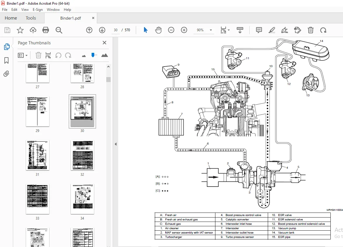
SUZUKI RH414D WITH 8HY ENGINE LIANA SUPPLEMENTARY SERVICE MANUAL – PDF DOWNLOAD
$29.95
Instant PDF Download
Available immediately
Save to Your Device
Download & keep forever
Antivirus Scanned
100% virus-free
Trusted Worldwide
175,000+ customers
Description
SUZUKI RH414D WITH 8HY ENGINE LIANA SUPPLEMENTARY SERVICE MANUAL – PDF DOWNLOAD
FILE DETAILS:
SUZUKI RH414D WITH 8HY ENGINE LIANA SUPPLEMENTARY SERVICE MANUAL – PDF DOWNLOAD
Language : English
Pages : 570
Downloadable : Yes
File Type : PDF
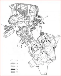
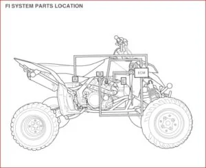
IMAGES PREVIEW OF THE MANUAL:
TABLE OF CONTENTS:
SUZUKI RH414D WITH 8HY ENGINE LIANA SUPPLEMENTARY SERVICE MANUAL – PDF DOWNLOAD
Bookcover..................................................................................................................................  1
99501-73J00-01E............................................................................................................................  2
	TOP....................................................................................................................................  2
	MANUAL LIST............................................................................................................................  2
	IMPORTANT..............................................................................................................................  2
	FOREWORD...............................................................................................................................  3
	TABLE OF CONTENTS......................................................................................................................  4
	Precautions............................................................................................................................  6
		Precautions........................................................................................................................  7
			Precautions....................................................................................................................  7
				General Precautions........................................................................................................  7
				Precaution for CAN Communication System....................................................................................  9
	General Information.................................................................................................................... 10
		General Information................................................................................................................ 11
			General Description............................................................................................................ 11
				Fasteners Information...................................................................................................... 11
				Engine Identification Number............................................................................................... 13
				Transmission Identification Number......................................................................................... 13
			Component Location............................................................................................................. 13
				Warning, Caution and Information Labels Location........................................................................... 13
		Maintenance and Lubrication........................................................................................................ 15
			Precautions.................................................................................................................... 15
				Precautions for Maintenance and Lubrication................................................................................ 15
			Scheduled Maintenance.......................................................................................................... 15
				Normal Condition Schedule.................................................................................................. 15
				Maintenance Recommended under Severe Driving Conditions.................................................................... 16
			Repair Instructions............................................................................................................ 16
				Engine Accessory Drive Belt Replacement.................................................................................... 16
				Engine Camshaft Timing Belt Replacement.................................................................................... 16
				Engine Oil and Oil Filter Replacement...................................................................................... 17
				Engine Coolant Inspection.................................................................................................. 18
				Engine Coolant Change...................................................................................................... 18
				Exhaust System Inspection.................................................................................................. 18
				Air Cleaner Filter Replacement............................................................................................. 18
				Fuel Lines and Connections Inspection...................................................................................... 19
				Fuel Filter Replacement.................................................................................................... 19
				Water Draining of Fuel Filter.............................................................................................. 19
				Fuel Tank Inspection....................................................................................................... 19
				Manual Transaxle Oil Inspection............................................................................................ 19
				Power Steering (P/S) System Inspection..................................................................................... 19
			Specifications................................................................................................................. 20
				Tightening Torque Specifications........................................................................................... 20
			Special Tools and Equipment.................................................................................................... 20
				Recommended Fluids and Lubricants.......................................................................................... 20
	Engine................................................................................................................................. 22
		Precautions........................................................................................................................ 26
			Precautions.................................................................................................................... 26
				Precautions for Engine..................................................................................................... 26
		Engine General Information and Diagnosis........................................................................................... 27
			Precautions.................................................................................................................... 27
				Precautions on Engine Service.............................................................................................. 27
				Precautions in Diagnosing Trouble.......................................................................................... 27
			General Description............................................................................................................ 28
				Statement on Cleanliness and Care.......................................................................................... 28
				Engine Diagnosis General Description....................................................................................... 28
				On-Board Diagnostic System Description..................................................................................... 28
			Schematic and Routing Diagram.................................................................................................. 30
				Air Intake System Diagram.................................................................................................. 30
				Electronic Control System Diagram.......................................................................................... 31
				Engine and Emission Control System Diagram................................................................................. 34
			Component Location............................................................................................................. 35
				Electronic Control System Components Location.............................................................................. 35
			Diagnostic Information and Procedures.......................................................................................... 36
				Engine and Emission Control System Check................................................................................... 36
				Malfunction Indicator Lamp (MIL) Check..................................................................................... 38
				DTC Check.................................................................................................................. 38
				DTC Clearance.............................................................................................................. 39
				DTC Table.................................................................................................................. 39
				Scan Tool Data............................................................................................................. 43
				Visual Inspection.......................................................................................................... 46
				Engine Basic Inspection.................................................................................................... 47
				Engine Symptom Diagnosis................................................................................................... 47
				Malfunction Indicator Lamp Does Not Come ON at Ignition Switch ON (But Engine at Stop)..................................... 65
				Malfunction Indicator Lamp Remains ON after Engine Starts.................................................................. 66
				DTC P0001 / P0003 / P0004: Fuel Volume Regulator Circuit................................................................... 67
				DTC P0002: Fuel Volume Regulator Control Circuit Performance............................................................... 68
				DTC P0069 / P0235 / P0236 / P0237 / P0238: Turbo Charger Boost Sensor Circuit.............................................. 69
				DTC P0089: Fuel Pressure Regulator Performance............................................................................. 71
				DTC P0101 / P0102 / P0103: Mass Air Flow Circuit........................................................................... 72
				DTC P0106 / P0107 / P0108: Barometric Pressure Circuit..................................................................... 73
				DTC P0111 / P0112 / P0113: Intake Air Temperature Sensor Circuit........................................................... 74
				DTC P0115 / P0116 / P0117 / P0118: Engine Coolant Temperature Circuit...................................................... 75
				DTC P0181 / P0182 / P0183: Fuel Temperature Sensor Circuit................................................................. 76
				DTC P0190 / P0192 / P0193: Fuel Rail Pressure.............................................................................. 77
				DTC P0201 / P0202 / P0203 / P0204: Injector Circuit Cylinder............................................................... 78
				DTC P0215: Engine Shutoff Solenoid......................................................................................... 79
				DTC P0222 / P0223 / P0227 / P0228 / P2137: Throttle Position Sensor Circuit................................................ 80
				DTC P0234 / P0299: Turbo Charger Boost Condition........................................................................... 81
				DTC P0243 / P0245 / P0246: Turbo Charger Wastegate Solenoid................................................................ 82
				DTC P0261 / P0264 / P0267 / P0270: Cylinder Circuit Low.................................................................... 83
				DTC P0262 / P0265 / P0268 / P0271: Cylinder Circuit High................................................................... 84
				DTC P0263 / P0266 / P0269 / P0272: Cylinder Balance........................................................................ 85
				DTC P0016 / P0335 / P0336 / P0337 / P0339: Crankshaft Position Sensor Circuit.............................................. 86
				DTC P0341 / P0343 / P0344: Camshaft Position Sensor Circuit................................................................ 88
				DTC P0400 / P0401 / P0402: Exhaust Gas Recirculation Flow.................................................................. 89
				DTC P0461 / P0462 / P0463: Fuel Level Sensor Circuit....................................................................... 90
				DTC P0480 / P0485: Fan No.1 Control Circuit................................................................................ 91
				DTC P0481: Fan 2 Control Circuit Malfunction............................................................................... 92
				DTC P0500 / P0501 / P0502: Vehicle Speed Sensor............................................................................ 93
				DTC P0532 / P0533: A/C Refrigerant Pressure Sensor Circuit................................................................. 94
				DTC P0562 / P0563: System Voltage.......................................................................................... 95
				DTC P0603 / P0604 / P0605 / P0606 / P1600 / P1613: ECM Internal Control Module Error....................................... 96
				DTC P0650: Malfunction Indicator Lamp (MIL) Circuit........................................................................ 97
				DTC P0658 / P0659: Actuator Supply Voltage Circuit......................................................................... 98
				DTC P0704: Clutch Switch Input Circuit Malfunction......................................................................... 99
				DTC P1110: A/C Cut Signal Circuit Malfunction..............................................................................100
				DTC P1160: MAF Sensor Circuit Plausibility.................................................................................101
				DTC P1163 / P1363: Knock Sensor Fault......................................................................................102
				DTC P1164: Fuel Pressure Sensor Signal Fault...............................................................................103
				DTC P1166: Fuel Rail Pressure Error........................................................................................104
				DTC P1207: Fuel Rail Pressure Regulator Circuit Malfunction................................................................105
				DTC P1349 / P1350: Pre/Post Heater Relay...................................................................................106
				DTC P1351 / P1352: Pre/Post Heater Relay Circuit...........................................................................107
				DTC P1536: Brake Information Fault.........................................................................................108
				DTC P1601: Main Relay Control Circuit Malfunction..........................................................................109
				DTC P1602: Glow Indicator Lamp Circuit Malfunction.........................................................................110
				DTC P1603: Engine Coolant Temperature Output Circuit.......................................................................111
				DTC P1605: Fuel Level Output Circuit.......................................................................................112
				DTC P1608: ECT Warning Lamp Circuit Malfunction............................................................................113
				DTC P1609: Engine Speed Output Circuit.....................................................................................114
				DTC P2143 / P2144 / P2145: EGR Vent Control Circuit........................................................................115
				DTC P2147 / P2148 / P2150 / P2151: Fuel Injector Circuit...................................................................116
				DTC P2299: Brake Pedal Position / Accelerator Pedal Position Incompatible..................................................117
				DTC P2670 / P2671: Power Supply Voltage....................................................................................118
				DTC P3007 / P3008: MAF Plausibility........................................................................................119
				System Check Table.........................................................................................................120
			Special Tools and Equipment....................................................................................................122
				Special Tool...............................................................................................................122
		Aux. Emission Control Devices......................................................................................................123
			Repair Instructions............................................................................................................123
				Vacuum Hose and Solenoid Valves Components.................................................................................123
				EGR Solenoid Valve Removal and Installation................................................................................123
				EGR Solenoid Valve Inspection..............................................................................................124
				Boost Pressure Control Solenoid Valve Inspection...........................................................................124
				Boost Pressure Control Solenoid Valve Removal and Installation.............................................................124
				Vacuum Pump Removal and Installation.......................................................................................125
				Vacuum Tank Removal and Installation.......................................................................................126
				Vacuum Tank Inspection.....................................................................................................126
				Vacuum Hose Inspection.....................................................................................................127
				EGR Valve Inspection.......................................................................................................127
			Specifications.................................................................................................................128
				Tightening Torque Specifications...........................................................................................128
			Special Tools and Equipment....................................................................................................128
				Special Tool...............................................................................................................128
		Engine Electrical Devices..........................................................................................................129
			Repair Instructions............................................................................................................129
				Idle Speed Inspection......................................................................................................129
				Engine Control Module (ECM) Removal and Installation.......................................................................129
				ECM Registration...........................................................................................................129
				Registration Data Check....................................................................................................130
				Pre/Post Heating Control Unit Removal and Installation.....................................................................131
				Glow Plug Removal and Installation.........................................................................................131
				Glow Plug Inspection.......................................................................................................132
				MAF Sensor Assembly with IAT Sensor Removal and Installation...............................................................132
				IAT Sensor Inspection......................................................................................................133
				Turbo Pressure Sensor Removal and Installation.............................................................................133
				Turbo Pressure Sensor Inspection...........................................................................................134
				TP Sensor Inspection.......................................................................................................134
				TP Sensor Removal and Installation.........................................................................................134
				ECT Sensor Removal and Installation........................................................................................135
				ECT Sensor Inspection......................................................................................................135
				Knock Sensor Removal and Installation......................................................................................135
				Knock Sensor Inspection....................................................................................................136
				CMP Sensor Removal and Installation........................................................................................136
				CMP Sensor Inspection......................................................................................................136
				CKP Sensor Removal and Installation........................................................................................137
				CKP Sensor Inspection......................................................................................................137
				Double Relay Removal and Installation......................................................................................137
				Double Relay Inspection....................................................................................................138
			Specifications.................................................................................................................139
				Tightening Torque Specifications...........................................................................................139
			Special Tools and Equipment....................................................................................................139
				Special Tool...............................................................................................................139
		Engine Mechanical..................................................................................................................140
			Precautions....................................................................................................................140
				Precaution on Crankshaft Timing Pulley.....................................................................................140
			Diagnostic Information and Procedures..........................................................................................140
				Compression Check..........................................................................................................140
			Repair Instructions............................................................................................................142
				Air Cleaner Components.....................................................................................................142
				Air Cleaner Element Removal and Installation...............................................................................143
				Air Cleaner Element Inspection and Cleaning................................................................................143
				Air Cleaner Assembly Removal and Installation..............................................................................144
				Accelerator Cable Adjustment...............................................................................................144
				Intercooler Components.....................................................................................................145
				Intercooler Removal and Installation.......................................................................................146
				Intercooler Inspection and Cleaning........................................................................................146
				Turbocharger Assembly Components...........................................................................................147
				Turbocharger Assembly Removal and Installation.............................................................................148
				Turbocharger Assembly Inspection...........................................................................................149
				Heat Exchanger and Oil Filter Block Components.............................................................................150
				Heat Exchanger and Oil Filter Block Removal and Installation...............................................................151
				EGR Valve and EGR Valve Pipe Removal and Installation......................................................................152
				Intake Manifold and Cylinder Head Cover Components.........................................................................153
				Cylinder Head Cover Removal and Installation...............................................................................153
				Intake Manifold Removal and Installation...................................................................................154
				Engine Mountings Components................................................................................................156
				Engine Assembly Removal and Installation...................................................................................157
				Timing Belt and Belt Tensioner Components..................................................................................160
				Timing Belt and Belt Tensioner Removal and Installation....................................................................160
				Timing Belt and Belt Tensioner Inspection..................................................................................165
				Camshaft Housing Components................................................................................................165
				Camshaft Housing Assembly Removal and Installation.........................................................................166
				Camshafts, Valve Rockers and Hydraulic Valve Adjuster Components...........................................................170
				Camshafts, Valve Rockers and Hydraulic Valve Adjuster Removal and Installation.............................................171
				Camshafts, Valve Rockers and Hydraulic Valve Adjuster Inspection...........................................................172
				Valves and Cylinder Head Components........................................................................................173
				Cylinder Head Assembly Removal and Installation............................................................................174
				Valves and Cylinder Head Assembly Inspection...............................................................................177
				Cylinder Head Assembly Disassembly and Assembly............................................................................177
				Valves and Valve Guides Inspection.........................................................................................178
				Cylinder Head Inspection...................................................................................................178
				Cylinder Head Bolt Inspection..............................................................................................179
				Lower Crankcase, Main Bearings, Crankshaft, Piston and Connecting Rod Assembly Components..................................179
				Lower Crankcase, Main Bearings, Crankshaft, Piston and Connecting Rod Assembly Removal and Installation....................180
				Piston and Connecting Rod Assembly Disassembly and Assembly................................................................184
				Cylinders, Pistons and Piston Rings Inspection.............................................................................185
				Piston Pins and Connecting Rods Inspection.................................................................................185
				Crank Pin and Connecting Rod Bearings Inspection...........................................................................186
				Main Bearings Inspection...................................................................................................186
				Flywheel Inspection........................................................................................................186
				Cylinder Block Inspection..................................................................................................186
			Specifications.................................................................................................................187
				Tightening Torque Specifications...........................................................................................187
			Special Tools and Equipment....................................................................................................188
				Recommended Service Material...............................................................................................188
				Special Tool...............................................................................................................188
		Engine Lubrication System..........................................................................................................191
			General Description............................................................................................................191
				Engine Lubrication Description.............................................................................................191
			Diagnostic Information and Procedures..........................................................................................191
				Oil Pressure Check.........................................................................................................191
			Repair Instructions............................................................................................................192
				Oil Pan and Oil Pump Strainer Components...................................................................................192
				Oil Pan and Oil Pump Strainer Removal and Installation.....................................................................193
				Oil Pan and Oil Pump Strainer Cleaning.....................................................................................194
				Oil Pump Components........................................................................................................195
				Oil Pump Removal and Installation..........................................................................................195
				Oil Pressure Switch Removal and Installation...............................................................................197
			Specifications.................................................................................................................198
				Tightening Torque Specifications...........................................................................................198
			Special Tools and Equipment....................................................................................................198
				Recommended Service Material...............................................................................................198
				Special Tool...............................................................................................................198
		Engine Cooling System..............................................................................................................199
			General Description............................................................................................................199
				Cooling System Description.................................................................................................199
				Coolant Description........................................................................................................199
			Schematic and Routing Diagram..................................................................................................200
				Coolant Circulation........................................................................................................200
			Diagnostic Information and Procedures..........................................................................................201
				Engine Cooling Symptom Diagnosis...........................................................................................201
			Repair Instructions............................................................................................................202
				Cooling System Components..................................................................................................202
				Coolant Level Check........................................................................................................203
				Engine Cooling System Inspection and Cleaning..............................................................................203
				Coolant Replacement........................................................................................................204
				Cooling Water Pipes or Hoses Removal and Installation......................................................................206
				Thermostat Assembly Removal and Installation...............................................................................206
				Radiator Cooling Fan Relay Inspection......................................................................................207
				Radiator On-Vehicle Inspection and Cleaning................................................................................207
				Radiator Removal and Installation..........................................................................................207
				Radiator Cooling Fan On-Vehicle Inspection.................................................................................209
				Radiator Cooling Fan Motor Removal and Installation........................................................................209
				Water Pump Removal and Installation........................................................................................209
				Water Pump Inspection......................................................................................................210
			Specifications.................................................................................................................210
				Tightening Torque Specifications...........................................................................................210
		Fuel System........................................................................................................................211
			Precautions....................................................................................................................211
				Precautions on Fuel System Service.........................................................................................211
				Precautions on Fuel System to Keep Clean...................................................................................212
			Schematic and Routing Diagram..................................................................................................215
				Fuel Delivery System Diagram...............................................................................................215
			Repair Instructions............................................................................................................216
				Fuel System Components.....................................................................................................216
				Fuel Pressure Relief Confirmation Procedure................................................................................217
				Fuel Leakage Check Procedure...............................................................................................217
				Water Draining of Fuel Filter..............................................................................................217
				Air Bleeding of Fuel System................................................................................................217
				Fuel Filter and Fuel Heater Removal and Installation.......................................................................217
				Fuel Heater Inspection.....................................................................................................219
				Fuel Lines Inspection......................................................................................................219
				Fuel Pipe Removal and Installation.........................................................................................219
				High Pressure Pipes Removal and Installation...............................................................................220
				Fuel Injector On-Vehicle Inspection........................................................................................224
				Fuel Injector Removal and Installation.....................................................................................224
				Fuel Temperature Sensor Assembly Removal and Installation..................................................................226
				Fuel Temperature Sensor Inspection.........................................................................................227
				Injection Pump Components..................................................................................................227
				Injection Pump Removal and Installation....................................................................................228
				Fuel Flow Actuator Inspection..............................................................................................230
				Fuel Flow Actuator Removal and Installation................................................................................230
				Common Rail (High Pressure Fuel Injection Rail) Removal and Installation...................................................231
				Fuel Presser Sensor Inspection.............................................................................................232
				Fuel Filler Cap Inspection.................................................................................................232
				Fuel Tank Removal and Installation.........................................................................................232
				Fuel Tank Inspection.......................................................................................................234
				Fuel Tank Purging Procedure................................................................................................234
				Fuel Tank Inlet Valve Removal and Installation.............................................................................235
				Fuel Tank Inlet Valve Inspection...........................................................................................235
				Fuel Level Gauge Assembly Components.......................................................................................235
				Fuel Level Gauge Assembly Removal and Installation.........................................................................236
				Fuel Level Gauge Assembly Inspection.......................................................................................237
			Specifications.................................................................................................................238
				Tightening Torque Specifications...........................................................................................238
			Special Tools and Equipment....................................................................................................238
				Recommended Service Material...............................................................................................238
				Special Tool...............................................................................................................238
		Starting System....................................................................................................................240
			Schematic and Routing Diagram..................................................................................................240
				Cranking System Circuit Diagram............................................................................................240
			Diagnostic Information and Procedures..........................................................................................240
				Cranking System Symptom Diagnosis..........................................................................................240
				Cranking System Test.......................................................................................................242
			Repair Instructions............................................................................................................243
				Starting Motor Dismounting and Remounting..................................................................................243
			Specifications.................................................................................................................243
				Tightening Torque Specifications...........................................................................................243
		Charging System....................................................................................................................244
			General Description............................................................................................................244
				Generator Description......................................................................................................244
			Diagnostic Information and Procedures..........................................................................................245
				Generator Symptom Diagnosis................................................................................................245
				Generator Test (Undercharged Battery Check)................................................................................245
				Generator Test (Overcharged Battery Check).................................................................................246
			Repair Instructions............................................................................................................247
				Generator Dismounting and Remounting.......................................................................................247
				Generator Components.......................................................................................................248
				Generator Inspection.......................................................................................................248
				Generator Drive Belt Removal and Installation..............................................................................250
				Generator Drive Belt Inspection............................................................................................250
				Generator Drive Belt Tensioner Removal and Installation....................................................................250
			Specifications.................................................................................................................251
				Charging System Specifications.............................................................................................251
				Tightening Torque Specifications...........................................................................................251
			Special Tools and Equipment....................................................................................................251
				Special Tool...............................................................................................................251
		Exhaust System.....................................................................................................................252
			General Description............................................................................................................252
				Exhaust System Description.................................................................................................252
			Repair Instructions............................................................................................................252
				Exhaust System Components..................................................................................................252
				Exhaust Manifold Components................................................................................................253
				Exhaust Manifold Removal and Installation..................................................................................253
				Catalytic Converter and Exhaust Pipe Removal and Installation..............................................................254
			Specifications.................................................................................................................254
				Tightening Torque Specifications...........................................................................................254
	Suspension.............................................................................................................................256
		Front Suspension...................................................................................................................258
			Repair Instructions............................................................................................................258
				Front Suspension Frame Components..........................................................................................258
				Front Suspension Frame Removal and Installation............................................................................259
				Front Suspension Frame Check...............................................................................................260
				Front Suspension Fasteners Check...........................................................................................260
			Specifications.................................................................................................................261
				Tightening Torque Specifications...........................................................................................261
	Driveline / Axle.......................................................................................................................262
		Drive Shaft / Axle.................................................................................................................263
			General Description............................................................................................................263
				Front Drive Shaft Construction.............................................................................................263
			Diagnostic Information and Procedures..........................................................................................263
				Front Drive Shaft Symptom Diagnosis........................................................................................263
			Repair Instructions............................................................................................................264
				Front Drive Shaft Components...............................................................................................264
				Drive Shaft Boot On-Vehicle Inspection.....................................................................................265
				Front Drive Shaft Assembly Removal and Installation........................................................................265
				Front Drive Shaft Disassembly and Assembly.................................................................................267
				Center Shaft Disassembly and Assembly......................................................................................273
			Specifications.................................................................................................................275
				Tightening Torque Specifications...........................................................................................275
			Special Tools and Equipment....................................................................................................275
				Recommended Service Material...............................................................................................275
				Special Tool...............................................................................................................275
	Brakes.................................................................................................................................276
		Brake Control System and Diagnosis.................................................................................................278
			Precautions....................................................................................................................278
				Precautions on Brake.......................................................................................................278
			General Description............................................................................................................279
				Brakes Construction........................................................................................................279
				Front Brake Hose / Pipe Construction.......................................................................................280
			Repair Instructions............................................................................................................282
				Master Cylinder Components.................................................................................................282
				Master Cylinder Reservoir Removal and Installation.........................................................................283
				Master Cylinder Assembly Removal and Installation..........................................................................283
				Master Cylinder Assembly Disassembly and Assembly..........................................................................284
				Master Cylinder Assembly Inspection........................................................................................285
				Brake Booster Components...................................................................................................286
				Booster Operation Inspection...............................................................................................287
				Brake Booster Removal and Installation.....................................................................................288
				Brake Booster Inspection and Adjustment....................................................................................289
			Specifications.................................................................................................................290
				Tightening Torque Specifications...........................................................................................290
			Special Tools and Equipment....................................................................................................290
				Special Tool...............................................................................................................290
		ABS................................................................................................................................291
			Repair Instructions............................................................................................................291
				ABS Hydraulic Unit / Control Module Assembly Components....................................................................291
				ABS Hydraulic Unit / Control Module Assembly Removal and Installation......................................................292
			Specifications.................................................................................................................293
				Tightening Torque Specifications...........................................................................................293
			Special Tools and Equipment....................................................................................................294
				Special Tool...............................................................................................................294
	Transmission / Transaxle...............................................................................................................296
		Precautions........................................................................................................................297
			Precautions....................................................................................................................297
				Precautions on Transmission / Transaxle....................................................................................297
		Manual Transmission/Transaxle......................................................................................................298
			General Description............................................................................................................298
				Manual Transaxle Construction..............................................................................................298
			Diagnostic Information and Procedures..........................................................................................299
				Manual Transaxle Symptom Diagnosis.........................................................................................299
			Repair Instructions............................................................................................................300
				Manual Transaxle Oil Change................................................................................................300
				Differential Side Oil Seal Replacement.....................................................................................300
				Gear Shift Control Lever and Cable Components..............................................................................301
				Gear Shift Control Lever and Cable Removal and Installation................................................................302
				Reverse Gear Switch Removal and Installation...............................................................................302
				Reverse Gear Switch Inspection.............................................................................................302
				Vehicle Speed Sensor (VSS) Removal and Installation........................................................................303
				Vehicle Speed Sensor (VSS) Inspection......................................................................................303
				Manual Transaxle Unit Components...........................................................................................304
				Manual Transaxle Unit Dismounting and Remounting...........................................................................305
				Manual Transaxle Assembly Components.......................................................................................306
				Gear Shift Shaft and Fork Components.......................................................................................307
				Gear Shift Shaft and Fork Inspection.......................................................................................308
				Manual Transaxle Assembly Disassembly and Reassembly.......................................................................308
				Manual Transaxle Assembly Inspection.......................................................................................315
				Primary Shaft Left Outer Race Removal and Installation.....................................................................315
				Primary Shaft Shim Adjustment..............................................................................................316
				Primary Shaft and Secondary Shaft Components...............................................................................317
				Primary Shaft Assembly Disassembly and Reassembly..........................................................................318
				Primary Shaft Assembly Inspection..........................................................................................319
				Secondary Shaft Assembly Disassembly and Reassembly........................................................................319
				Secondary Shaft Assembly Inspection........................................................................................320
				Differential Assembly Components...........................................................................................321
				Differential Removal and Installation......................................................................................321
				Differential Components....................................................................................................323
				Differential Disassembly and Assembly......................................................................................323
				Differential Shim Adjustment...............................................................................................324
			Specifications.................................................................................................................325
				Tightening Torque Specifications...........................................................................................325
			Special Tools and Equipment....................................................................................................326
				Recommended Service Material...............................................................................................326
				Special Tool...............................................................................................................326
		Clutch.............................................................................................................................328
			General Description............................................................................................................328
				Clutch Construction........................................................................................................328
			Diagnostic Information and Procedures..........................................................................................328
				Clutch System Symptom Diagnosis............................................................................................328
			Repair Instructions............................................................................................................329
				Clutch Pedal Inspection....................................................................................................329
				Clutch Pedal Switch Removal and Installation...............................................................................329
				Clutch Pedal Switch Inspection.............................................................................................330
				Clutch Fluid Inspection....................................................................................................330
				Clutch Fluid Pipe and Hose Components......................................................................................331
				Clutch Fluid Pipe and Hose Removal and Installation........................................................................332
				Clutch Fluid Pipe and Hose Inspection......................................................................................332
				Clutch Master Cylinder Removal and Installation............................................................................332
				Clutch Master Cylinder Components..........................................................................................333
				Clutch Master Cylinder Inspection..........................................................................................334
				Clutch Operating Cylinder Removal and Installation.........................................................................334
				Clutch Operating Cylinder Inspection.......................................................................................334
				Clutch Cover, Clutch Disc, Flywheel and Clutch Release System Components...................................................335
				Clutch Cover, Clutch Disc and Flywheel Removal and Installation............................................................335
				Clutch Cover, Clutch Disc and Flywheel Inspection..........................................................................337
				Clutch Release System Removal and Installation.............................................................................337
				Clutch Release Bearing Guide Replacement...................................................................................338
				Clutch Release System Inspection...........................................................................................338
			Specifications.................................................................................................................339
				Tightening Torque Specifications...........................................................................................339
			Special Tools and Equipment....................................................................................................339
				Recommended Service Material...............................................................................................339
				Special Tool...............................................................................................................339
	Steering...............................................................................................................................340
		Precautions........................................................................................................................341
			Precautions....................................................................................................................341
				Precautions on Steering....................................................................................................341
		Steering General Diagnosis.........................................................................................................342
			Precautions....................................................................................................................342
				Precautions for Steering, Suspension, Wheels and Tires Diagnosis...........................................................342
			Diagnostic Information and Procedures..........................................................................................342
				Steering Symptom Diagnosis.................................................................................................342
		Power Assisted Steering System.....................................................................................................343
			Precautions....................................................................................................................343
				P/S System Note............................................................................................................343
			General Description............................................................................................................343
				P/S System Description.....................................................................................................343
			Diagnostic Information and Procedures..........................................................................................344
				P/S System Symptom Diagnosis...............................................................................................344
				Hydraulic Pressure in P/S Circuit Check....................................................................................345
			Repair Instructions............................................................................................................347
				P/S Fluid Leakage Check....................................................................................................347
				P/S Pump Drive Belt Removal and Installation...............................................................................347
				P/S Pump Drive Belt Inspection.............................................................................................347
				P/S Gear Box Components....................................................................................................348
				P/S Gear Box Removal and Installation......................................................................................349
				Tie-Rod / Rack Boot Removal and Installation...............................................................................350
				P/S Pump Components........................................................................................................352
				P/S Pump Removal and Installation..........................................................................................353
				P/S Pump Disassembly and Assembly..........................................................................................353
				P/S Pump Inspection........................................................................................................355
			Specifications.................................................................................................................356
				P/S System Specification and Service Data..................................................................................356
				Tightening Torque Specifications...........................................................................................357
			Special Tools and Equipment....................................................................................................357
				Recommended Service Material...............................................................................................357
				Special Tool...............................................................................................................357
	HVAC...................................................................................................................................358
		Precautions........................................................................................................................361
			Precautions....................................................................................................................361
				Precautions on HVAC........................................................................................................361
		Heater and Ventilation.............................................................................................................362
			Precautions....................................................................................................................362
				Precautions in Diagnosing Trouble..........................................................................................362
			General Description............................................................................................................363
				Additional Heater Assembly Description.....................................................................................363
				On-Board Diagnostic System Description.....................................................................................364
			Schematic and Routing Diagram..................................................................................................365
				Heater and Ventilation Wiring Circuit Diagram..............................................................................365
			Diagnostic Information and Procedures..........................................................................................366
				Heater and Ventilation Symptom Diagnosis...................................................................................366
				DTC Check..................................................................................................................367
				DTC Clearance..............................................................................................................368
				DTC Table..................................................................................................................369
				Fail-Safe Table............................................................................................................371
				Scan Tool Data.............................................................................................................371
				DTC B1501 (No.01): Outside Air Temperature Sensor and/or its Circuit Malfunction...........................................372
				DTC B1510 (No.10): Engine Coolant Temperature (ECT) Sensor and/or its Circuit Malfunction..................................372
				DTC B1511 (No.11): Temperature Control Actuator (Position Sensor) and/or its Circuit Malfunction...........................372
				DTC B1512 (No.12): Air Flow Control Actuator (Position Sensor) and/or its Circuit malfunction..............................372
				DTC B1513 (No.13): Temperature Control Actuator and/or its Circuit malfunction.............................................372
				DTC B1514 (No.14): Air Flow Control Actuator and/or its Circuit malfunction................................................372
				DTC B1523 (No.23): Additional Heater and/or its Circuit Malfunction........................................................372
				DTC B1524 (No.24): Engine Speed Signal Circuit Malfunction.................................................................373
				Inspection of HVAC Control Module and its Circuit..........................................................................373
			Repair Instructions............................................................................................................377
				Outside Air Temperature Sensor Removal and Installation....................................................................377
				Outside Air Temperature Sensor Inspection..................................................................................377
				Additional Heater Assembly Removal and Installation........................................................................377
				Additional Heater Assembly On-Vehicle Inspection...........................................................................377
				Additional Heater Relays Inspection........................................................................................378
			Specifications.................................................................................................................378
				Tightening Torque Specifications...........................................................................................378
			Special Tools and Equipment....................................................................................................378
				Special Tool...............................................................................................................378
		Air Conditioning System............................................................................................................379
			Manual Type....................................................................................................................379
				Precautions................................................................................................................379
					Precaution in Diagnosing Trouble.......................................................................................379
					Precautions on Servicing A/C System....................................................................................379
				General Description........................................................................................................381
					A/C Evaporator Outlet Air Temperature Sensor Construction..............................................................381
					On-Board Diagnostic System Description.................................................................................381
				Schematic and Routing Diagram..............................................................................................382
					Major Components of A/C System.........................................................................................382
					A/C System Wiring Diagram..............................................................................................383
				Diagnostic Information and Procedures......................................................................................384
					A/C System Symptom Diagnosis...........................................................................................384
					DTC Check..............................................................................................................386
					DTC Clearance..........................................................................................................386
					DTC Table..............................................................................................................387
					Fail-Safe Table........................................................................................................389
					Scan Tool Data.........................................................................................................389
					DTC B1501 (No.01): Outside Air Temperature Sensor and/or its Circuit Malfunction.......................................390
					DTC B1503 (No.03): A/C Evaporator Air Temperature Sensor and/or its Circuit Malfunction................................390
					DTC B1510 (No.10): Engine Coolant Temperature (ECT) Sensor and/or its Circuit Malfunction..............................390
					DTC B1511 (No.11): Temperature Control Actuator (Position Sensor) and/or its Circuit Malfunction.......................391
					DTC B1512 (No.12): Air Flow Control Actuator (Position Sensor) and/or its Circuit malfunction..........................391
					DTC B1513 (No.13): Temperature Control Actuator and/or its Circuit malfunction.........................................391
					DTC B1514 (No.14): Air Flow Control Actuator and/or its Circuit malfunction............................................391
					DTC B1523 (No.23): Additional Heater and/or its Circuit Malfunction....................................................391
					DTC B1524 (No.24): Engine Speed Signal Circuit Malfunction.............................................................391
					Inspection of HVAC Control Module and its Circuit......................................................................391
				Repair Instructions........................................................................................................395
					Operation Procedure for Refrigerant Charging...........................................................................395
					Heater and Cooling Unit Components.....................................................................................400
					Heater and Cooling Unit Removal and Installation.......................................................................400
					Condenser Assembly Removal and Installation............................................................................401
					Desiccant Removal and Installation.....................................................................................402
					A/C Evaporator Removal and Installation................................................................................402
					A/C Evaporator Outlet Air Temperature Sensor Removal and Installation..................................................403
					A/C Evaporator Outlet Air Temperature Sensor Inspection................................................................404
					A/C Refrigerant Pressure Sensor Removal and Installation...............................................................404
					A/C Refrigerant Pressure Sensor Inspection.............................................................................404
					Outside Air Temperature Sensor Removal and Installation................................................................405
					Outside Air Temperature Sensor Inspection..............................................................................405
					Compressor Relay Inspection............................................................................................405
					Compressor Drive Belt Removal and Installation.........................................................................405
					Compressor Drive Belt Inspection.......................................................................................405
					Compressor Removal and Installation....................................................................................405
					Compressor Inspection..................................................................................................406
					Magnet Clutch Components...............................................................................................406
					Magnet Clutch Removal and Installation.................................................................................407
				Specifications.............................................................................................................408
					Tightening Torque Specifications.......................................................................................408
				Special Tools and Equipment................................................................................................409
					Recommended Service Material...........................................................................................409
					Special Tool...........................................................................................................409
			Automatic Type.................................................................................................................410
				Precautions................................................................................................................410
					Precautions in Diagnosing Trouble......................................................................................410
					Precautions on Servicing A/C System....................................................................................410
				General Description........................................................................................................410
					A/C System Introduction................................................................................................410
					On-Board Diagnostic System Description.................................................................................411
				Schematic and Routing Diagram..............................................................................................412
					Major Components of A/C System.........................................................................................412
					A/C System Wiring Diagram..............................................................................................413
				Diagnostic Information and Procedures......................................................................................414
					A/C System Symptom Diagnosis...........................................................................................414
					DTC Check..............................................................................................................417
					DTC Clearance..........................................................................................................418
					DTC Table..............................................................................................................419
					Fail-Safe Table........................................................................................................422
					Scan Tool Data.........................................................................................................422
					DTC B1501 (No.01): Outside Air Temperature Sensor and/or its Circuit Malfunction.......................................424
					DTC B1502 (No.02): Inside Air Temperature Sensor and/or its Circuit Malfunction........................................425
					DTC B1503 (No.03): A/C Evaporator Air Temperature Sensor and/or its Circuit Malfunction................................426
					DTC B1504 (No.04): Sunload Sensor and/or its Circuit Malfunction.......................................................427
					DTC B1510 (No.10): Engine Coolant Temperature (ECT) Sensor and/or its Circuit Malfunction..............................428
					DTC B1511 (No.11): Temperature Control Actuator (Position Sensor) and/or its Circuit Malfunction.......................430
					DTC B1512 (No.12): Air Flow Control Actuator (Position Sensor) and/or its Circuit malfunction..........................431
					DTC B1513 (No.13): Temperature Control Actuator and/or its Circuit malfunction.........................................433
					DTC B1514 (No.14): Air Flow Control Actuator and/or its Circuit malfunction............................................435
					DTC B1523 (No.23): Additional Heater and/or Its Circuit Malfunction....................................................438
					DTC B1524 (No.24): Engine Speed Signal Circuit Malfunction.............................................................440
					Inspection of HVAC Control Module and its Circuit......................................................................442
				Repair Instructions........................................................................................................446
					Operation Procedure for Refrigerant Charging...........................................................................446
					Heater and Cooling Unit Removal and Installation.......................................................................446
					Condenser Assembly Removal and Installation............................................................................446
					Desiccant Removal and Installation.....................................................................................446
					A/C Evaporator Removal and Installation................................................................................446
					A/C Evaporator Outlet Air Temperature Sensor Removal and Installation..................................................446
					A/C Evaporator Outlet Air Temperature Sensor Inspection................................................................446
					A/C Refrigerant Pressure Sensor Removal and Installation...............................................................446
					A/C Refrigerant Pressure Sensor Inspection.............................................................................446
					Compressor Relay Inspection............................................................................................446
					Compressor Drive Belt Removal and Installation.........................................................................446
					Compressor Drive Belt Inspection.......................................................................................446
					Compressor Removal and Installation....................................................................................446
					Compressor Inspection..................................................................................................446
					Magnet Clutch Components...............................................................................................446
					Magnet Clutch Removal and Installation.................................................................................446
				Special Tools and Equipment................................................................................................447
					Special Tool...........................................................................................................447
	Body, Cab and Accessories..............................................................................................................448
		Precautions........................................................................................................................452
			Precautions....................................................................................................................452
				Precautions on Body, Cab and Accessories...................................................................................452
				Precautions for Body Service...............................................................................................452
				Fastener Caution for Body Service..........................................................................................452
		Wiring Systems.....................................................................................................................453
			Precautions....................................................................................................................453
				Cautions in Body Electrical System Servicing...............................................................................453
				Precautions for Wiring System..............................................................................................453
			General Description............................................................................................................454
				Abbreviations..............................................................................................................454
				Wire / Connector Color Symbols.............................................................................................454
				Symbols and Marks..........................................................................................................455
				How to Read Connector Layout Diagram.......................................................................................457
				How to Read Connector Codes and Terminal Nos...............................................................................458
				How to Read Ground Point...................................................................................................460
				How to Read Power Supply Diagram...........................................................................................461
				How to Read System Circuit Diagram.........................................................................................461
			Harness Routing and Connector Layout Diagram...................................................................................463
				Connector Layout Diagram...................................................................................................463
				Engine Compartment for Connector Layout Diagram............................................................................463
				Instrument Panel for Connector Layout Diagram..............................................................................465
				Door, Roof for Connector Layout Diagram....................................................................................467
				Floor for Connector Layout Diagram.........................................................................................468
				Rear for Connector Layout Diagram..........................................................................................471
			Ground Point...................................................................................................................473
				Ground (earth) Point.......................................................................................................473
			Power Supply Diagram...........................................................................................................475
				Power Supply Diagram.......................................................................................................475
				Fuses and the Protected Parts..............................................................................................477
				Fuses in Main Fuse Box.....................................................................................................477
				Individual Circuit Fuse Box, Supplementary Fuse Box (No. 1), Supplementary Fuse Box (No. 2)................................477
			System Circuit Diagram.........................................................................................................479
				System Circuit Diagram.....................................................................................................479
				A-1 Cranking System Circuit Diagram........................................................................................480
				A-2 Charging System Circuit Diagram........................................................................................481
				A-4 Cooling System Circuit Diagram.........................................................................................482
				A-5 Engine and A/C Control System Circuit Diagram..........................................................................483
				A-7 Immobilizer Control System Circuit Diagram.............................................................................487
				B-1 Windshield Wiper and Washer Circuit Diagram............................................................................488
				B-2 Rear Wiper and Washer Circuit Diagram (Instrument Panel Switch Type)...................................................489
				B-2 Rear Wiper and Washer Circuit Diagram (Column Lever Switch Type).......................................................490
				B-3 Rear Defogger Circuit Diagram..........................................................................................491
				B-4 Power Window Circuit Diagram...........................................................................................492
				B-5 Power Door Lock Circuit Diagram........................................................................................494
				B-6 Power Mirror Circuit Diagram...........................................................................................496
				B-7 Horn Circuit Diagram...................................................................................................497
				B-8 Seat Heater Circuit Diagram............................................................................................498
				C-1 Combination Meter Circuit Diagram (Meter)..............................................................................499
				C-2 Combination Meter Circuit Diagram (Indicator)..........................................................................500
				C-3 Combination Meter Circuit Diagram (Warning Light)......................................................................501
				D-1 Headlight System Circuit Diagram.......................................................................................503
				D-2 Position, Tail and Licence Plate Light Circuit Diagram.................................................................504
				D-3 Fog Light Circuit Diagram..............................................................................................505
				D-4 Illumination Light Circuit Diagram.....................................................................................506
				D-5 Interior Light Circuit Diagram.........................................................................................507
				D-6 Turn Signal and Hazard Warning Light Circuit Diagram...................................................................508
				D-7 Brake Light Circuit Diagram............................................................................................509
				D-8 Back-Up Light Circuit Diagram..........................................................................................510
				D-9 Headlight Beam Leveling System Circuit Diagram.........................................................................511
				D-10 Rear fog light Circuit Diagram........................................................................................512
				E-2 Auto A/C System Circuit Diagram........................................................................................513
				E-3 PTC Heater.............................................................................................................515
				F-1 Air-Bag Control System Circuit Diagram.................................................................................516
				F-2 Anti-Lock Brake System Circuit Diagram.................................................................................518
				G-1 Radio / Cigar Lighter Circuit Diagram..................................................................................520
				G-2 Clock Circuit Diagram..................................................................................................522
			List of Connectors.............................................................................................................523
				List of Connectors.........................................................................................................523
				C Connector................................................................................................................523
				D Connector................................................................................................................524
				E Connector................................................................................................................524
				G Connector................................................................................................................526
				J Connector................................................................................................................527
				K Connector................................................................................................................528
				L Connector................................................................................................................528
				M Connector................................................................................................................530
				O Connector (for 5 Door)...................................................................................................530
		Instrumentation / Driver Info. / Horn..............................................................................................531
			Schematic and Routing Diagram..................................................................................................531
				Combination Meter Circuit Diagram..........................................................................................531
			Diagnostic Information and Procedures..........................................................................................532
				Speedometer and VSS Symptom Diagnosis......................................................................................532
				Fuel Meter Symptom Diagnosis...............................................................................................532
				Low Fuel Warning Light Symptom Diagnosis...................................................................................533
				Oil Pressure Warning Light Symptom Diagnosis...............................................................................533
				High Engine Coolant Temperature Warning Light Symptom Diagnosis............................................................533
				Information Display (If Equipped) Symptom Diagnosis........................................................................534
			Repair Instructions............................................................................................................535
				Fuel Level Sensor Removal and Installation.................................................................................535
				Fuel Level Sensor Inspection...............................................................................................535
				Oil Pressure Switch Removal and Installation...............................................................................535
				Oil Pressure Switch On-Vehicle Inspection..................................................................................535
				VSS Removal and Installation...............................................................................................535
				VSS Inspection.............................................................................................................535
				Engine Coolant Temperature (ECT) Sensor Inspection.........................................................................535
		Body Structure.....................................................................................................................536
			Specifications.................................................................................................................536
				Body Dimensions............................................................................................................536
	Control systems........................................................................................................................546
		Immobilizer Control System.........................................................................................................547
			Precautions....................................................................................................................547
				Precautions in Diagnosing Troubles.........................................................................................547
				Precautions in Replacing ECM or Immobilizer Control Module.................................................................547
				Precautions in Handling Immobilizer Control System.........................................................................547
			General Description............................................................................................................548
				Immobilizer Control System Introduction....................................................................................548
				Immobilizer Control System Components Location.............................................................................549
				On-Board Diagnostic System Description (Self- diagnosis Function)..........................................................549
			Schematic and Routing Diagram..................................................................................................550
				Immobilizer Control System Wiring Circuit Diagram..........................................................................550
			Diagnostic Information and Procedures..........................................................................................551
				Immobilizer Control System Check...........................................................................................551
				Diagnostic Trouble Code (DTC) Check........................................................................................551
				Diagnostic Trouble Code (DTC) Table........................................................................................552
				Scan Tool Data.............................................................................................................552
				Communication Error between Immobilizer Control Module and SUZUKI Scan Tool................................................553
				DTC B1000: Transponder EEPROM Malfunction..................................................................................555
				DTC B1001: Transponder Code Error..........................................................................................555
				DTC B4002: Transponder Antenna Malfunction.................................................................................557
				DTC B1003: Coil Antenna Malfunction........................................................................................559
				DTC B1004: Immobilizer Control Module EEPROM Malfunction:..................................................................560
				DTC B3005: Short to Ground Circuit in Wire Connection Between Immobilizer Indicator Lamp and Immobilizer Control Module....561
				DTC B4005: Open in Wire Connection Between Immobilizer Indicator Lamp and Immobilizer Control Module.......................561
				DTC B4006: Open in Wire Connection Between Standby LED and Immobilizer Control Module......................................562
				DTC U1007: CAN Communication Error between Immobilizer Control Module and ECM..............................................563
				DTC U1008: Open or Short in CAN Communication Lines between Immobilizer Control Module and ECM.............................564
				Inspection of Immobilizer Control Module and Its Circuit...................................................................565
			Repair Instructions............................................................................................................566
				Immobilizer Control Module Removal and Installation........................................................................566
				Coil Antenna Removal and Installation......................................................................................566
				Coil Antenna Inspection....................................................................................................567
				Registration of Transponder Code in Ignition Key...........................................................................567
				Procedure after Immobilizer Control Module Replacement.....................................................................567
				Procedure after ECM Replacement............................................................................................567
			Special Tools and Equipment....................................................................................................568
				Special Tool...............................................................................................................568
	COPYRIGHT..............................................................................................................................569
	BOOKCOVER..............................................................................................................................570
S.S