Trusted Business
Verified & Licensed
Virus Free Files
100% Safe Downloads
Secure Payment
SSL Protected
Instant Delivery
Available Immediately
SUZUKI SQ420VD SQ420WD WITH RHW ENGINE GRAND VITARA SUPPLEMENTARY SERVICE MANUAL – PDF DOWNLOAD
$32.95
Instant PDF Download
Available immediately
Save to Your Device
Download & keep forever
Antivirus Scanned
100% virus-free
Trusted Worldwide
175,000+ customers
Description
SUZUKI SQ420VD SQ420WD WITH RHW ENGINE GRAND VITARA SUPPLEMENTARY SERVICE MANUAL – PDF DOWNLOAD
FILE DETAILS:
SUZUKI SQ420VD SQ420WD WITH RHW ENGINE GRAND VITARA SUPPLEMENTARY SERVICE MANUAL – PDF DOWNLOAD
Language : English
Pages : 747
Downloadable : Yes
File Type : PDF
IMAGES PREVIEW OF THE MANUAL:
TABLE OF CONTENTS:
SUZUKI SQ420VD SQ420WD WITH RHW ENGINE GRAND VITARA SUPPLEMENTARY SERVICE MANUAL – PDF DOWNLOAD
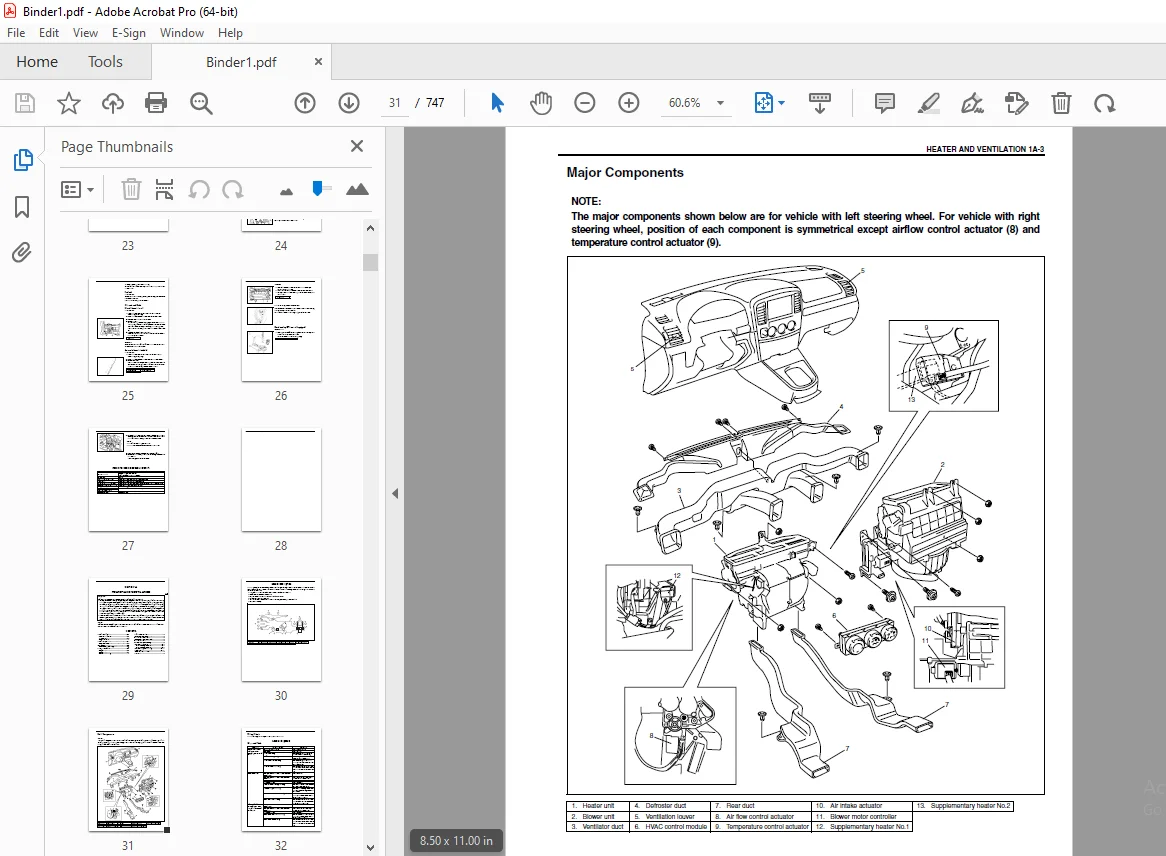
Bookcover...........................................................................................................  1
99501_68D10_01E.....................................................................................................  2
	TOP.............................................................................................................  0
	Manual List.....................................................................................................  0
	Important.......................................................................................................  2
		WARNING/CAUTION/NOTE........................................................................................  2
	Foreword........................................................................................................  3
	Table of Contents...............................................................................................  5
	SECTION 0A......................................................................................................  7
		Precautions.................................................................................................  8
			General Precautions.....................................................................................  8
		Identification Information.................................................................................. 11
			Vehicle Identification Number........................................................................... 11
			Engine Identification Number............................................................................ 11
			Transmission Identification Number...................................................................... 11
		Warning, Caution and Information Labels..................................................................... 12
		Metric Information.......................................................................................... 13
			Metric Fasteners........................................................................................ 13
	SECTION 0B...................................................................................................... 15
		Maintenance Schedule........................................................................................ 16
			Maintenance Schedule Under Normal Driving Conditions.................................................... 16
			Maintenance Recommended Under Severe Driving Conditions................................................. 17
		Maintenance Service......................................................................................... 19
			Engine.................................................................................................. 19
				Accessary drive belt................................................................................ 19
				Camshaft timing belt................................................................................ 20
				Engine oil and oil filter........................................................................... 20
				Engine coolant...................................................................................... 22
				Exhaust system...................................................................................... 23
				Heater (Glow) plugs................................................................................. 23
			Fuel System............................................................................................. 24
				Air cleaner filter.................................................................................. 24
				Fuel lines and connections.......................................................................... 24
				Fuel filter......................................................................................... 24
				Fuel tank........................................................................................... 25
			Chassis and Body........................................................................................ 25
				Manual transmission oil............................................................................. 25
				Automatic transmission fluid........................................................................ 25
				Power steering (P/S) system (if equipped)........................................................... 26
		Recommended Fluids and Lubricants........................................................................... 27
	SECTION 1A...................................................................................................... 29
		General Description......................................................................................... 30
			Major Components........................................................................................ 31
			Wiring Circuit.......................................................................................... 32
		General Diagnosis........................................................................................... 32
			Diagnosis Table......................................................................................... 32
		HVAC Diagnosis.............................................................................................. 33
			On-Board Diagnostic System.............................................................................. 33
		On-Vehicle Service.......................................................................................... 34
			Blower Unit............................................................................................. 34
			Blower Motor............................................................................................ 35
			Supplementary Heater.................................................................................... 37
				Supplementary heater No.1........................................................................... 37
				Supplementary heater No.2........................................................................... 37
			Supplementary Heater Relay.............................................................................. 38
			Heater Unit............................................................................................. 39
	SECTION 1B...................................................................................................... 43
		Major Components and Location............................................................................... 45
		Wiring Circuit.............................................................................................. 46
		General Diagnosis........................................................................................... 48
			General Diagnosis Table................................................................................. 48
			Inspection of HVAC Control Module and Its Circuits...................................................... 53
				HVAC control module voltage table................................................................... 54
				Reference waveform No.1............................................................................. 57
				Reference waveform No.2............................................................................. 58
				Reference graph No.1................................................................................ 59
			Inspection of A/C Controller and Its Circuits........................................................... 60
				A/C controller voltage value table.................................................................. 61
			Scan Tool Data.......................................................................................... 62
				Scan tool data definitions.......................................................................... 63
		On-Vehicle Service.......................................................................................... 66
			Heater and Cooling Unit................................................................................. 66
			A/C Controller.......................................................................................... 69
			A/C Signal Relay........................................................................................ 69
			A/C Compressor Relay and A/C Condenser Cooling Fan Relays............................................... 70
			Compressor Assembly..................................................................................... 70
			Compressor Drive Belt................................................................................... 73
		Required Service Materials.................................................................................. 73
			Special Tool............................................................................................ 74
	SECTION 3B1..................................................................................................... 75
		General Description......................................................................................... 77
			Power Steering (P/S) Pump............................................................................... 77
		Diagnosis................................................................................................... 78
			Power Steering Fluid.................................................................................... 78
				Power steering fluid level check.................................................................... 78
			Power Steering Pump Drive Belt.......................................................................... 78
			Hydraulic Pressure in P/S Circuit....................................................................... 78
				Hydraulic pressure check............................................................................ 78
		On-Vehicle Service.......................................................................................... 80
			Power Steering Gear Box Assembly........................................................................ 80
			Power Steering Pump..................................................................................... 82
		Tightening Torque Specifications............................................................................ 89
		Required Service Material................................................................................... 89
		Special Tool................................................................................................ 90
	SECTION 3E...................................................................................................... 91
		On-vehicle Service.......................................................................................... 92
			Rear Axle Shaft and Wheel Bearing....................................................................... 92
			Rear Axle Housing....................................................................................... 92
		Tightening Torque Specification............................................................................. 93
		Required Service Material................................................................................... 93
	SECTION 5....................................................................................................... 95
		Check and Adjustment........................................................................................ 96
			Fluid Pressure Test (if equipped with LSPV)............................................................. 96
		Tightening Torque Specification............................................................................. 98
		Required Service Material................................................................................... 98
		Special Tool................................................................................................ 99
	SECTION 6-1.....................................................................................................101
		OTHER THAN EOBD SPEC........................................................................................105
		General Information.........................................................................................105
			Identification of Emission Control System...............................................................105
			Statement of Cleanliness and Care.......................................................................105
			General Information on Engine Service...................................................................106
				Precaution on fuel system service...................................................................107
				Fuel pressure relief procedure......................................................................108
				Fuel leakage check procedure........................................................................108
		Engine Diagnosis............................................................................................109
			General Description.....................................................................................109
			On-Board Diagnostic System..............................................................................109
			Precaution in Diagnosing Trouble........................................................................112
			Engine Diagnostic Flow Table............................................................................113
				Diagnostic step details.............................................................................114
			Malfunction Indicator Lamp (MIL) Check..................................................................117
			Diagnostic Trouble Code (DTC) Check.....................................................................117
			Diagnostic Trouble Code (DTC) Clearance.................................................................117
			Fail-Safe Table.........................................................................................118
			Diagnostic Trouble Code (DTC) Table.....................................................................119
			Visual Inspection.......................................................................................123
			Engine Basic Check......................................................................................124
			Engine Diagnosis Table..................................................................................125
			Inspection of ECM and Its Circuits......................................................................131
				Voltage check.......................................................................................131
				Resistance check....................................................................................133
			Table A-1 Malfunction Indicator Lamp Circuit Check – MIL Does Not Come “ON” or Dims at Ignition S.......134
			Table A-2 Malfunction Indicator Lamp Circuit Check – MIL Remains “ON” after Engine Starts...............135
			Table A-3 ECM Power and Ground Circuit Check – MIL Doesn’t Light at Ignition Switch ON and Engine.......136
			DTC P0100 (DTC P0100) Mass Air Flow Circuit Malfunction.................................................137
			DTC P0101 (P0100) MAF Sensor Circuit Range/Performance Problem..........................................140
			DTC P0110 Intake Air Temp. (IAT) Circuit Malfunction....................................................141
			DTC P0115 (DTC P0115) Engine Coolant Temp. Sensor Circuit Malfunction...................................143
			DTC P0121 (DTC P0120) Throttle Position Circuit Range/Performance Problem...............................145
			DTC P0604 (P0120) Throttle Position Sensor Monitoring System Malfunction................................145
			DTC P0180 Fuel Temperature Sensor Circuit Malfunction...................................................147
			DTC P0190 (P0190) Fuel Rail Pressure Sensor Circuit Malfunction.........................................149
			DTC P0191 (P0230) Fuel Rail Pressure Sensor/Pressure Regulator Consistency Function.....................151
			DTC P1112 (P0230) Fuel Pressure Monitoring Circuit Malfunction..........................................151
			DTC P0201 (P0200) Injector Circuit Malfunction Cylinder 1...............................................153
			DTC P0202 (P0200) Injector Circuit Malfunction Cylinder 2...............................................153
			DTC P0203 (P0200) Injector Circuit Malfunction Cylinder 3...............................................153
			DTC P0204 (P0200) Injector Circuit Malfunction Cylinder 4...............................................153
			DTC P0215 Double Relay Circuit Malfunction..............................................................155
			DTC P0230 Fuel Pump Supply Circuit Malfunction..........................................................157
			DTC P0243 (P0243) Turbo Pressure Solenoid Valve Circuit Range/Performance Problem.......................159
			DTC P0245 (P0243)/P0246 (P0243) Turbo Pressure Solenoid Valve Circuit Range/Performance Problem.........161
			DTC P0380 (P0380)/P1404 (P0380) Pre/Post Heat Relay Circuit Malfunction.................................162
			DTC P0381 Glow Indicator Lamp Circuit Malfunction.......................................................164
			DTC P0401 (P0903) EGR Solenoid Valve Flow Insufficient Detected.........................................166
			DTC P0402 (P0903) EGR Solenoid Valve Flow Excessive Detected............................................166
			DTC P0403 (P0403) EGR Solenoid Valve Circuit Malfunction................................................167
			DTC P0561 (P0560) Stabilization of Sensor Supply........................................................169
			DTC P0603/P0606/P1171 ECM Function......................................................................169
			DTC P1169 (P0170) Condenser Voltage Function 1..........................................................169
			DTC P1170 (P0170) Condenser Voltage Function 2..........................................................169
			DTC P1101 (P0105) Barometric Pressure Sensor Circuit Malfunction........................................169
			DCT P1107 Swirl Control Solenoid Valve Circuit Malfunction..............................................170
			DTC P1108 Radiator Fan High Speed Circuit Malfunction...................................................172
			DTC P1109 Radiator Fan Low Speed Circuit Malfunction....................................................174
			DTC P1110 A/C Signal Circuit Malfunction................................................................175
			DTC P1135 3rd Piston Deactivator (Injection Pump Solenoid Valve) Circuit Malfunction....................176
			DTC P1138 (P0230) Fuel Pressure Regulator Circuit Malfunction...........................................178
			DTC P1402 (P0510) Throttle Solenoid Valve Circuit Malfunction...........................................180
			DTC P1511 Ignition Switch Circuit Malfunction...........................................................182
			DTC P1519 Radiator Fan Circuit Malfunction..............................................................183
			DTC P1606 MIL Circuit Malfunction.......................................................................184
			DTC P1608 ECT Warning Lamp Circuit Malfunction..........................................................186
			DTC P1614 (P0560) Sensor Supply Function................................................................188
			DTC P0221 (P0220) Throttle Position Range/Performance Problem 2.........................................191
			DTC P0335 (P0335) Crankshaft Position Sensor Circuit Malfunction........................................193
			DTC P0340 (P0335/P0340) Camshaft Position Sensor Circuit Malfunction....................................195
			DTC P0500 (P0500) Vehicle Speed Sensor Circuit Malfunction..............................................198
			DTC P0235 (P0235) Intake Air Pressure Sensor Circuit Malfunction........................................200
			DTC P0560 (P0560) Power Supply Circuit Malfunction......................................................202
			DTC P1613 ECM Not Registered............................................................................203
			DTC P1517 Immobilizer System Malfunction................................................................204
			TABLE B-1 Fuel Pump Circuit Inspection..................................................................206
			TABLE B-2 Fuel Pressure Inspection......................................................................207
		EOBD SPEC...................................................................................................208
		General Information.........................................................................................208
			Identification of Emission Control System...............................................................208
			Statement of Cleanliness and Care.......................................................................208
			General Information on Engine Service...................................................................209
				Precaution on fuel system service...................................................................210
				Fuel pressure relief procedure......................................................................211
				Fuel leakage check procedure........................................................................211
		Engine Diagnosis............................................................................................212
			General Description.....................................................................................212
			On-Board Diagnostic System..............................................................................212
			Precaution in Diagnosing Trouble........................................................................215
			Engine Diagnostic Flow Table............................................................................216
				Diagnostic step details.............................................................................217
			Malfunction Indicator Lamp (MIL) Check..................................................................220
			Diagnostic Trouble Code (DTC) Check.....................................................................220
			Diagnostic Trouble Code (DTC) Clearance.................................................................220
			Fail-Safe Table.........................................................................................221
			Diagnostic Trouble Code (DTC) Table.....................................................................224
			Visual Inspection.......................................................................................229
			Engine Basic Check......................................................................................230
			Engine Diagnosis Table..................................................................................231
			Inspection of ECM and Its Circuits......................................................................237
				Voltage check.......................................................................................237
				Resistance check....................................................................................239
			Table A-1 Malfunction Indicator Lamp Circuit Check – MIL Does Not Come “ON” or Dims at Ignition S.......240
			Table A-2 Malfunction Indicator Lamp Circuit Check – MIL Remains “ON” after Engine Starts...............241
			Table A-3 ECM Power and Ground Circuit Check – MIL Doesn’t Light at Ignition Switch ON and Engine.......242
			DTC P0100 (P0102/P0103/P3007/P3008) Mass Air Flow Circuit (Low Input/High Input/Plausibility at L.......243
			DTC P0110 (P0112/P0113) Intake Air Temperature Sensor Circuit (Low/High)................................246
			DTC P0115 (P0115/P0117/P0118) Engine Coolant Temperature Circuit (Malfunction/Low/High).................248
			DTC P0220 (P0222/P0223/P0224) Pedal Position Sensor “No.1” Circuit (Low/ High/Intermittent).............250
			DTC P2299 Accelerator Pedal Position Incompatible.......................................................250
			DTC P0180 (P0182/P0183) Fuel Temperature Sensor Circuit (Low/High)......................................252
			DTC P0190 (P0192/P0193/P0194) Fuel Rail Pressure Sensor Circuit (Low/High/ Intermittent)................254
			DTC P0089 (P0089/P0087, P1113/P0088, P1116/P0094) Fuel Pressure Regulator Performance (Malfunctio.......256
			DTC P0201 (P0201/P0261/P0262/P1372) Injector Circuit – Cylinder 1 (Malfunction/Low/High/ Short).........258
			DTC P0202 (P0202/P0264/P0265/P1373) Injector Circuit – Cylinder 2 (Malfunction/Low/High/ Short).........260
			DTC P0203 (P0203/P0267/P0268/P1374) Injector Circuit – Cylinder 3 (Malfunction/Low/High/ Short).........262
			DTC P0204 (P0204/P0267/P0268/P1374) Injector Circuit – Cylinder 4 (Malfunction/Low/High/ Short).........264
			DTC P1169 Condenser 1 Voltage Too Low/High..............................................................266
			DTC P1170 Condenser 2 Voltage Too Low/High..............................................................266
			DTC P0215 Engine Shutoff Solenoid.......................................................................269
			DTC P0230 Fuel Pump Primary Circuit.....................................................................271
			DTC P0243 (P0243/P0246) Turbo Charger Waste Gate Solenoid (Malfunction/ High)...........................273
			DTC P0245 (P0245) Turbo Charger Waste Gate Solenoid Low.................................................273
			DTC P0234 (P0243) Turbo Charger Over Boost Condition....................................................275
			DTC P0299 (P0299) Turbo Charger Under Boost.............................................................275
			DTC P0380 (P1351/P1352/P1349/P1350) Glow Plug Circuit (Excess Voltage/ Relay Jammed/Short/Open).........276
			DTC P1404 TL4226 Circuit Malfunction....................................................................276
			DTC P0381 Glow Plug Indicator Circuit...................................................................278
			DTC P0401 (P0401) Exhaust Gas Recirculation Flow Insufficient Detected..................................280
			DTC P0400 (P0400/P0402/P2143/P2145) Exhaust Gas Recirculation Flow (Malfunction/Excessive Detecte.......281
			DTC P2144 (P2144) Exhaust Gas Recirculation Vent Control Circuit Low....................................281
			DTC P0105 (P0107/P0108) Barometric Pressure Sensor Circuit (Low Input/ High Input)......................283
			DTC P0561 (P0642/P0643) Sensor Reference Voltage Circuit (Low/High).....................................283
			DTC P0603 (P0603) Internal Control Module Keep Alive Memory (KAM) Error.................................283
			DTC P0604 (P0604) Internal Control Module Random Access Memory (RAM) Error..............................283
			DTC P1107 (P2009/P2010) Intake Manifold Runner Control Circuit (Low/High)...............................284
			DTC P0480 Fan 1 Control Circuit.........................................................................286
			DTC P0481 Fan 2 Control Circuit.........................................................................288
			DTC P3004 (P3005/P3006) 3rd Piston Deactivator Circuit (Short/Open).....................................289
			DTC P0090 (P0090/P0091/P0092) Fuel Pressure Regulator Control Circuit (Malfunction/Low/High)............291
			DTC P0606 (P0606) ECM Processor.........................................................................291
			DTC P1171 ECU Function (ECU Internal Fault).............................................................291
			DTC P0120 (P0487/P2142) Exhaust Gas Recirculation Throttle Position Control Circuit (Malfunction/.......293
			DTC P2141 (P2141) Exhaust Gas Recirculation Throttle Position Control Circuit Low.......................293
			DTC P1511 Ignition Switch Circuit Malfunction...........................................................295
			DTC P0485 Fan Power/Ground Circuit......................................................................296
			DTC P0650 (P0650/P1642) Malfunction Indicator Lamp (MIL) Control Circuit Malfunction (Malfunction.......297
			DTC P0608 (P0658/P0659) Actuator Supply Voltage Circuit 1 (Low/High)....................................299
			DTC P0609 (P2670/P2671) Actuator Supply Voltage Circuit 2 (Low/High)....................................301
			DTC P0225 (P0224/P0227/P0228/P2137) Pedal Position Sensor “No.2” Circuit (Intermittent/Low/High/V.......304
			DTC P0335 (P0335) Crankshaft Position Sensor Circuit....................................................306
			DTC P0340 (P0341/P0343/P0344/P0016) Camshaft Position Sensor Circuit (Performance/High/Intermitte.......308
			DTC P0500 (P0500/P0501) Vehicle Speed Sensor (Malfunction/Performance)..................................311
			DTC P0235 (P0069/P0235, P1281/P0237/P0238) Turbo Charger Boost Sensor Circuit (Manifold Absolute .......313
			DTC P0560 (P0562/P0563) System Voltage (Low/High).......................................................315
			DTC P1613 ECM Not Registered............................................................................316
			DTC P1517 Immobilizer System Malfunction................................................................317
			TABLE B-1 Fuel Pump Circuit Inspection..................................................................319
			TABLE B-2 Fuel Pressure Inspection......................................................................320
		Special Tool................................................................................................321
	SECTION 6A3.....................................................................................................323
		CONTENTS....................................................................................................323
		Service Precaution..........................................................................................324
		On-Vehicle Service..........................................................................................324
			Compression Check.......................................................................................324
			Oil Pressure Check......................................................................................325
			Air Cleaner Element.....................................................................................326
			Intercooler.............................................................................................327
			Cylinder Head Cover.....................................................................................328
			Turbocharger............................................................................................332
			Intake Manifold.........................................................................................334
			Exhaust Manifold........................................................................................334
			Timing Belt and Belt Tensioner..........................................................................337
			Oil Pressure Switch.....................................................................................345
			Oil Cooler..............................................................................................345
			Oil Pan and Oil Pump Strainer...........................................................................346
			Oil Pump................................................................................................351
			Camshafts and Valve Rockers.............................................................................355
			Valves and Cylinder Head................................................................................362
			Swirl Control Solenoid Valve............................................................................369
			Piston, Piston Rings, Connecting Rods and Cylinders.....................................................371
		Unit Repair Overhaul........................................................................................376
			Engine Assembly.........................................................................................376
			Main Bearings, Crankshaft and Cylinder Block............................................................379
		Special Tools...............................................................................................389
		Required Service Materials..................................................................................390
		Tightening Torque Specifications............................................................................391
	SECTION 6B......................................................................................................393
		General Description.........................................................................................394
			Cooling System Component................................................................................394
			Cooling System Circulation..............................................................................395
			Coolant Degassing Tank..................................................................................396
			Water Pump..............................................................................................396
			Thermostat..............................................................................................396
			Cooling Fan.............................................................................................397
			Coolant.................................................................................................397
				Anti-freeze proportioning chart:....................................................................397
				Coolant capacity....................................................................................397
		Diagnosis...................................................................................................398
			Diagnosis Table.........................................................................................398
		Maintenance.................................................................................................399
			Coolant Level Check.....................................................................................399
			Cooling System Service..................................................................................399
			Cooling System Flush....................................................................................400
			On-Vehicle Service......................................................................................402
			Cooling System Draining.................................................................................402
			Cooling System Refill...................................................................................402
			Cooling Water Pipes or Hoses............................................................................402
			Thermostat..............................................................................................403
			Radiator................................................................................................405
			Radiator Fan Relay......................................................................................406
			Water Pump..............................................................................................406
		Required Service Materials..................................................................................408
		Tightening Torque Specifications............................................................................408
		Special Tool................................................................................................408
	SECTION 6C......................................................................................................409
		General Description.........................................................................................410
			Fuel System.............................................................................................410
		On-Vehicle Service..........................................................................................410
			Water Draining of Fuel Filter...........................................................................410
			Air Bleeding of Fuel System.............................................................................410
			Fuel Filter Assembly....................................................................................410
				Fuel filter assembly components.....................................................................410
				Fuel filter element.................................................................................411
				Fuel filter assembly................................................................................412
			Fuel Tank Assembly......................................................................................414
				Fuel tank assembly components.......................................................................414
				2-way check valve (tank pressure control valve).....................................................414
				Fuel tank...........................................................................................415
			Fuel Pump and Fuel Level Gauge..........................................................................416
				Fuel pump...........................................................................................417
				Fuel level gauge....................................................................................418
			Injection Pump..........................................................................................418
		Tightening Torque Specifications............................................................................419
		Special Tools...............................................................................................419
	SECTION 6E3.....................................................................................................421
		General Description.........................................................................................423
			Identification of Emission Control System...............................................................423
			System Diagram..........................................................................................424
			Electronic Control System...............................................................................425
				System location diagram.............................................................................425
				System wiring diagram...............................................................................426
			Air Intake System.......................................................................................430
			Fuel Delivery System....................................................................................431
		On-Vehicle Service..........................................................................................432
			Accelerator Cable Adjustment............................................................................432
			Idle Speed Inspection...................................................................................432
			Air Intake System.......................................................................................433
				Vacuum hose routing diagram.........................................................................433
				Throttle valve assembly.............................................................................434
				EGR throttle solenoid valve.........................................................................435
				Vacuum pump.........................................................................................435
				Boost pressure regulator solenoid valve.............................................................438
				Glow plug...........................................................................................439
			Fuel Delivery System....................................................................................441
				Precautions.........................................................................................441
				Low pressure fuel supply system.....................................................................443
			Fuel Leakage Check......................................................................................444
				Fuel pump...........................................................................................444
				Fuel heater.........................................................................................444
				Fuel injector.......................................................................................445
				Common rail (High pressure fuel injection rail).....................................................448
				Injection pump......................................................................................451
			Electronic Control System...............................................................................454
				Engine control module (ECM).........................................................................454
				ECM registration....................................................................................455
				Registration data check.............................................................................456
				Mass air flow sensor (MAF sensor)...................................................................456
				Throttle position sensor (TP sensor) (accelerator pedal position sensor)............................458
				Fuel temperature sensor assembly....................................................................459
				Fuel (rail) pressure sensor.........................................................................460
				Engine coolant temperature sensor (ECT sensor)......................................................461
				VSS.................................................................................................462
				Camshaft position sensor (CMP sensor)...............................................................463
				Crankshaft position sensor (engine speed sensor)....................................................463
				Intake air pressure sensor (manifold absolute pressure sensor)......................................465
				Radiator fan control system.........................................................................466
				Radiator fan........................................................................................466
				Radiator fan relay 1 (high/low).....................................................................467
				Radiator fan relay 2 (high).........................................................................468
				Radiator fan relay 3 (low)..........................................................................468
				Double relay........................................................................................469
				Pre/post heating relay (control unit)...............................................................470
			EGR System..............................................................................................471
				EGR valve component.................................................................................471
				EGR valve and EGR cooler............................................................................472
				Vacuum hose.........................................................................................473
				EGR solenoid valve..................................................................................473
			Swirl Control Solenoid Valve............................................................................474
		Tightening Torque Specifications............................................................................476
		Special Tools...............................................................................................477
	SECTION 6G......................................................................................................479
		General Description.........................................................................................480
			Cranking Circuit........................................................................................480
			Starting Motor Circuit..................................................................................480
			Starting Motor..........................................................................................481
		Diagnosis...................................................................................................482
		Unit Repair Overhaul........................................................................................483
			Generator...............................................................................................483
				Dismounting.........................................................................................483
				Remounting..........................................................................................483
				Disassembly and reassembly..........................................................................484
				Inspection..........................................................................................485
				Performance test....................................................................................488
		Specifications..............................................................................................489
			2.0 kW reduction type...................................................................................489
		Required Service Materials..................................................................................489
		Tightening Torque Specifications............................................................................490
	SECTION 6H......................................................................................................491
		On-Vehicle Service..........................................................................................492
			Generator...............................................................................................492
				Generator belt......................................................................................492
		Unit Repair Overhaul........................................................................................494
			Generator...............................................................................................494
		Specifications..............................................................................................497
			Generator...............................................................................................497
		Tightening Torque Specifications............................................................................497
		Special Tools...............................................................................................497
	SECTION 6K......................................................................................................499
		General Description.........................................................................................500
			Exhaust System Components...............................................................................500
		Maintenance.................................................................................................501
		On-Vehicle Service..........................................................................................502
			Exhaust Manifold........................................................................................502
			Muffler.................................................................................................502
	SECTION 7A2.....................................................................................................503
		General Description.........................................................................................504
			System Description......................................................................................504
		Diagnosis...................................................................................................504
		On-Vehicle Service..........................................................................................505
			Transmission Gear Oil...................................................................................505
			Transmission Shift Control Lever........................................................................506
			Back Up Light Switch....................................................................................506
			Engine Rear Mounting....................................................................................506
			Dismounting of Transmission Unit........................................................................506
			Remounting of Transmission Unit.........................................................................508
		Unit Repair.................................................................................................510
		Tightening Torque Specifications............................................................................510
	SECTION 7B1.....................................................................................................511
		General Description.........................................................................................513
			Clutch/Brake Functions..................................................................................515
			Table of Component Operation............................................................................516
			Electronic Shift Control System.........................................................................517
				Change mechanism....................................................................................519
				Operation of shift solenoids and TCC solenoid.......................................................519
		Diagnosis...................................................................................................521
			On-Board Diagnostic System..............................................................................521
			Precaution in Diagnosing Trouble........................................................................522
			Automatic Transmission Diagnostic Flow Table............................................................523
			“O/D OFF” Lamp Check....................................................................................526
			Diagnostic Trouble Code (DTC) Check.....................................................................526
			Diagnostic Trouble Code Clearance.......................................................................528
			Diagnostic Trouble Code Table...........................................................................529
			Fail Safe Table.........................................................................................531
			Visual Inspection.......................................................................................532
			A/T Basic Check.........................................................................................533
			Trouble Diagnosis Table 1...............................................................................534
			Trouble Diagnosis Table 2...............................................................................536
			Trouble Diagnosis Table 3...............................................................................537
			Engine Brake Test.......................................................................................541
			Stall Test..............................................................................................541
			Time Lag Test...........................................................................................543
			Line Pressure Test......................................................................................544
			“P” Range Test..........................................................................................545
			Table A-1: No Gear Shift to O/D.........................................................................546
			Table A-2: No Lock-Up Occurs............................................................................547
			Table B-1: “O/D OFF” Lamp Circuit Check (“O/D OFF” Lamp Doesn’t Light at Ignition Switch On)............548
			Table B-2: “O/D OFF” Lamp Circuit Check (“O/D OFF” Lamp Comes On Steadily)..............................549
			Inspection of TCM and Its Circuits......................................................................550
			Wire Harness and Connectors.............................................................................551
			Scan Tool Data..........................................................................................552
			Scan Tool Data Definition...............................................................................553
			DTC P0705 (DTC NO.34) Transmission Range Sensor (Switch) Circuit Malfunction............................554
			DTC P0710 (DTC NO.36/38) Transmission Fluid Temperature Sensor Circuit Malfunction......................557
			DTC P0715 (DTC NO.37) Input/Turbine Speed Sensor Circuit Malfunction....................................559
			DTC P0720 (DTC NO.31) Output Speed Sensor Circuit Malfunction...........................................562
			DTC P0725 (DTC NO.35) Engine Speed Input Circuit Malfunction............................................565
			DTC P0743 (DTC NO.25/26) TCC (Lock-Up) System Electrical................................................567
			DTC P0748 (DTC NO.41/42) Pressure Control Solenoid Electrical...........................................569
			DTC P0753 (DTC NO.21/22)/ P0758 (DTC NO.23/24) Shift Solenoid-A/ Shift Solenoid-B Electrical............571
			DTC P1700 (DTC NO.32/33) Acceleration Stroke Signal Input Malfunction...................................573
			DTC P1702 (DTC NO.52) Internal Malfunction of TCM.......................................................575
			DTC P1730 (DTC NO.64) Engine Torque Signal Circuit Malfunction..........................................576
		On-Vehicle Service..........................................................................................578
			Maintenance Service.....................................................................................578
				Fluid level.........................................................................................578
				Fluid change........................................................................................579
			Oil Cooler Hoses........................................................................................580
			Manual Selector Assembly................................................................................580
			Select Cable............................................................................................582
			Transmission Range Sensor (Switch)......................................................................583
			Input Shaft Speed Sensor................................................................................584
			Output Shaft Speed Sensor...............................................................................585
			A/T Fluid Temperature Sensor............................................................................587
			O/D Off Switch..........................................................................................587
			Solenoid Valves (Shift Solenoid Valves, TCC Solenoid Valve and Pressure Control Solenoid Valve).........588
			Throttle Position Sensor................................................................................591
			Transmission Control Module (TCM).......................................................................591
			4WD LOW Switch..........................................................................................592
			Oil Cooler Pipes........................................................................................592
			Automatic Transmission Assembly (with Transfer).........................................................593
		Unit Repair.................................................................................................599
			Precautions.............................................................................................599
			Part Inspection and Correction Table....................................................................600
			Unit Disassembly........................................................................................601
			Subassembly.............................................................................................618
				Oil pump assembly...................................................................................618
				O/D clutch assembly and O/D planetary gear assembly.................................................622
				O/D brake assembly..................................................................................628
				Direct clutch assembly..............................................................................632
				Forward clutch assembly.............................................................................636
				Sun gear and one-way No.3 clutch assembly...........................................................641
				Forward brake assembly..............................................................................643
				Rear planetary gear carrier assembly and output shaft...............................................646
				Valve body assembly.................................................................................651
			Unit Assembly...........................................................................................652
		Tightening Torque Specifications............................................................................671
		Required Service Material...................................................................................672
		Special Tool................................................................................................672
	SECTION 7C1.....................................................................................................675
		CONTENTS....................................................................................................675
		Unit Pepair.................................................................................................676
			Clutch Cover, Clutch Disc and Flywheel..................................................................676
		Tightening Torque Specifications............................................................................679
		Required Service Material...................................................................................680
		Special Tool................................................................................................680
	SECTION 7E......................................................................................................681
		General Description.........................................................................................681
			4WD Control System......................................................................................682
				System circuit and operation........................................................................683
				Components and functions............................................................................684
		Diagnosis...................................................................................................685
			Diagnosis Table.........................................................................................685
				Differential assembly...............................................................................685
				4WD control system diagnostic flow table............................................................685
			4WD Control Circuit Inspection..........................................................................688
				Voltage check.......................................................................................688
		On-Vehicle Service..........................................................................................689
			Maintenance Service.....................................................................................689
				Gear oil change.....................................................................................689
			Removal and Installation................................................................................690
				Differential mountings..............................................................................690
				Rear mounting (for front differential carrier)......................................................692
			Dismounting.............................................................................................692
			Remounting..............................................................................................694
		Unit Repair.................................................................................................695
		Tightening Torque Specifications............................................................................695
		Required Service Material...................................................................................695
		Special Tool................................................................................................695
	SECTION 7F......................................................................................................697
		General Description.........................................................................................698
		Diagnosis...................................................................................................698
		On-vehicle Service..........................................................................................699
			Maintenance Service.....................................................................................700
				Changing oil........................................................................................700
			Rear Differential Assembly..............................................................................701
				Dismounting.........................................................................................701
				Remounting..........................................................................................701
		Unit Repair.................................................................................................702
			Disassembling Unit......................................................................................702
			Component Inspection....................................................................................705
			Sub-Assembly Adjustment and Reassembly..................................................................705
				Differential carrier................................................................................705
				Differential case...................................................................................705
				Differential side bearing...........................................................................707
				Drive bevel pinion..................................................................................708
			Assembling Unit.........................................................................................712
		Tightening Torque Specification.............................................................................715
		Required Service Material...................................................................................715
		Special Tool................................................................................................716
	SECTION 8C......................................................................................................719
		General Description.........................................................................................720
			Combination Meter.......................................................................................720
				Combination meter internal circuits and couplers....................................................720
		On-Vehicle Service..........................................................................................722
			Fuel Meter/Fuel Gauge Unit..............................................................................722
				Fuel level gauge....................................................................................722
			Engine Coolant Temperature (ECT) Sensor.................................................................722
			Oil Pressure Switch.....................................................................................722
	SECTION 8G......................................................................................................723
		General Description.........................................................................................724
			Wiring Circuit..........................................................................................725
			Ignition Key............................................................................................726
			Coil Antenna............................................................................................726
			Immobilizer Control Module..............................................................................726
			ECM.....................................................................................................726
			On-board Diagnostic System (Self-diagnosis Function)....................................................727
		Diagnosis...................................................................................................728
			Precautions in Diagnosing Troubles......................................................................728
				Precautions in identifying diagnostic trouble code..................................................728
				Note on system circuit inspection...................................................................728
			Precautions after Replacing ECM or Immobilizer Control Module...........................................728
			Immobilizer Control System Diagnostic Flow Table........................................................729
			Diagnostic Trouble Code (DTC) Check (Immobilizer Control Module)........................................730
			Diagnostic Trouble Code Table...........................................................................730
			Table A – Scan Tool Can Not Communicate with Immobilizer Control Module.................................731
			DTC11 Transponder Code Not Matched......................................................................732
			DTC31 Transponder Code Not Registered...................................................................732
			DTC12 Fault in Immobilizer Control Module...............................................................733
			DTC13 No Transponder Code Transmitted from Ignition Key.................................................733
			DTC14 Coil Antenna Circuit Malfunction..................................................................733
			DTC41 ECM Not Registered................................................................................735
			DTC42 Serial Data Circuit Malfunction (Between Immobilizer Control Module and ECM)......................736
			DTC43 ECU Code Not Matched..............................................................................737
			Inspection of Immobilizer Control Module and Its Circuit................................................738
		On-Vehicle Service..........................................................................................740
			Precautions in Handling Immobilizer Control System......................................................740
			Immobilizer Control Module..............................................................................741
			Coil Antenna............................................................................................741
			How to Register Ignition Key............................................................................742
			Procedure after Immobilizer Control Module Replacement..................................................743
			Procedure after ECM Replacement.........................................................................744
		Special Tools...............................................................................................745
	Copyright.......................................................................................................747
	Bookcover.......................................................................................................  0
S.S