Trusted Business
Verified & Licensed
Virus Free Files
100% Safe Downloads
Secure Payment
SSL Protected
Instant Delivery
Available Immediately
Suzuki Swift RS413 RS415 RS416 RS413D Supplementary Service Manual – PDF DOWNLOAD
$30.00
Suzuki Swift RS413 RS415 RS416 RS413D Supplementary Service Manual – PDF DOWNLOAD
Instant PDF Download
Available immediately
Save to Your Device
Download & keep forever
Antivirus Scanned
100% virus-free
Trusted Worldwide
175,000+ customers
Description
Suzuki Swift RS413 RS415 RS416 RS413D Supplementary Service Manual – PDF DOWNLOAD
FILE DETAILS:
Suzuki Swift RS413 RS415 RS416 RS413D Supplementary Service Manual – PDF DOWNLOAD
Language : English
Pages : 658
Downloadable : Yes
File Type : PDF
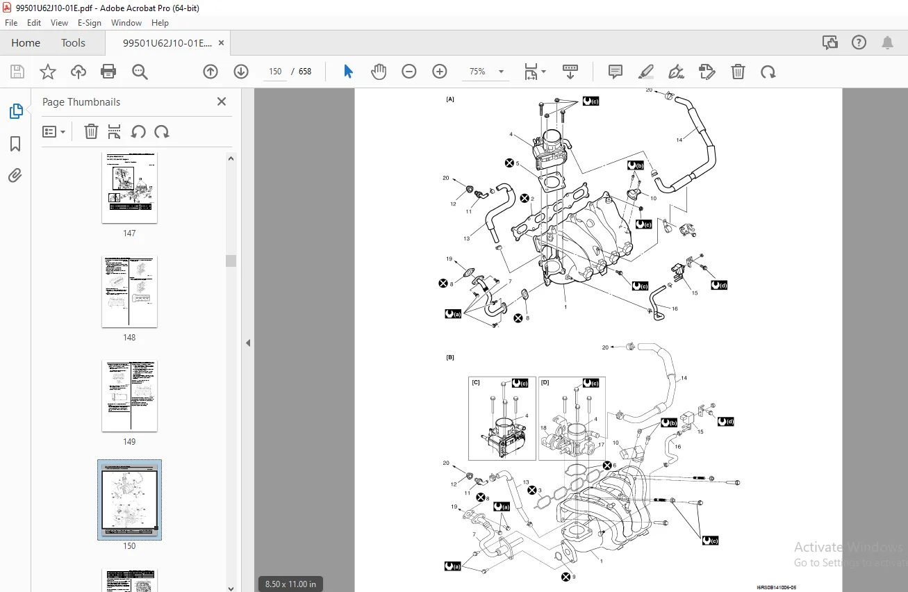
IMAGES PREVIEW OF THE MANUAL:
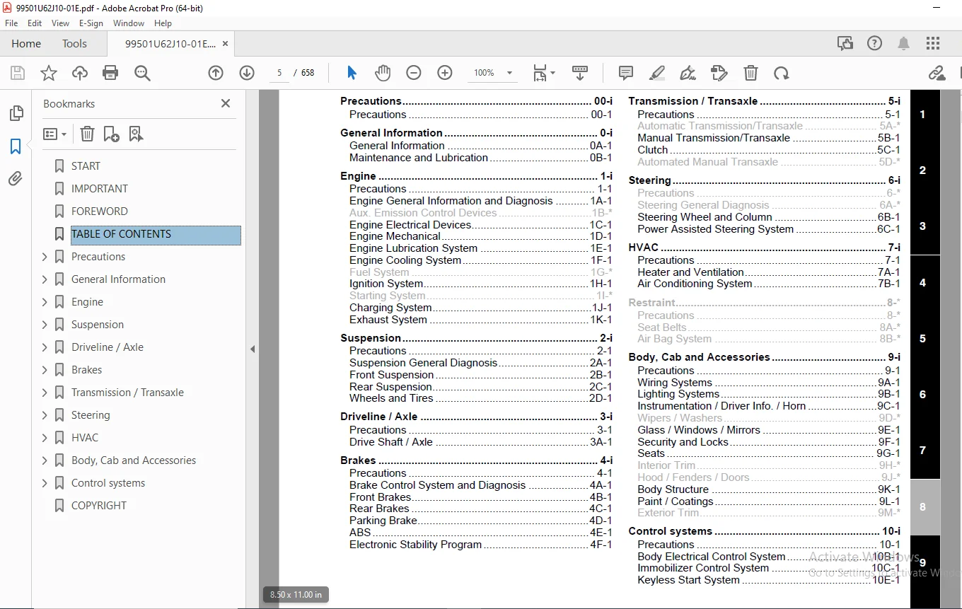
TABLE OF CONTENTS:
Suzuki Swift RS413 RS415 RS416 RS413D Supplementary Service Manual – PDF DOWNLOAD
START..................................................................................................................................................................................................................................................................  1
IMPORTANT..............................................................................................................................................................................................................................................................  1
FOREWORD...............................................................................................................................................................................................................................................................  3
TABLE OF CONTENTS......................................................................................................................................................................................................................................................  5
Precautions............................................................................................................................................................................................................................................................  7
	Precautions........................................................................................................................................................................................................................................................  8
		Precautions....................................................................................................................................................................................................................................................  8
			Precaution for Vehicle Equipped with ESP‚ System...........................................................................................................................................................................................................  8
			Brake Caution..............................................................................................................................................................................................................................................  8
General Information....................................................................................................................................................................................................................................................  9
	General Information................................................................................................................................................................................................................................................ 11
		General Description............................................................................................................................................................................................................................................ 11
			Abbreviations.............................................................................................................................................................................................................................................. 11
	Maintenance and Lubrication........................................................................................................................................................................................................................................ 13
		Scheduled Maintenance.......................................................................................................................................................................................................................................... 13
			Maintenance Schedule under Normal Driving Conditions (Petrol Engine Model)................................................................................................................................................................................. 13
		Repair Instructions............................................................................................................................................................................................................................................ 14
			Brake Discs and Pads Inspection............................................................................................................................................................................................................................ 14
		Special Tools and Equipment.................................................................................................................................................................................................................................... 14
			Recommended Fluids and Lubricants (Petrol Engine Model).................................................................................................................................................................................................... 14
Engine................................................................................................................................................................................................................................................................. 15
	Precautions........................................................................................................................................................................................................................................................ 24
		For M13, M15 and M16 Engines................................................................................................................................................................................................................................... 24
			Precautions................................................................................................................................................................................................................................................ 24
				Precautions for Engine................................................................................................................................................................................................................................. 24
		For Z13DT Engine............................................................................................................................................................................................................................................... 25
			Precautions................................................................................................................................................................................................................................................ 25
				Precautions for Engine................................................................................................................................................................................................................................. 25
	Engine General Information and Diagnosis........................................................................................................................................................................................................................... 26
		For M13, M15 and M16 Engines................................................................................................................................................................................................................................... 26
			Precautions................................................................................................................................................................................................................................................ 26
				Precautions of Electric Throttle Body System Calibration (Electric Throttle Body Model)................................................................................................................................................................ 26
			General Description........................................................................................................................................................................................................................................ 27
				CAN Communication System Description................................................................................................................................................................................................................... 27
				Description of Electric Throttle Body System (Electric Throttle Body Model)............................................................................................................................................................................ 30
				Fuel Cut Control Description (M16A Engine)............................................................................................................................................................................................................. 31
				Generator Control System Description (M16A Engine)..................................................................................................................................................................................................... 31
				Electronic Control System Description.................................................................................................................................................................................................................. 32
				Engine and Emission Control Input / Output Table....................................................................................................................................................................................................... 40
			Schematic and Routing Diagram.............................................................................................................................................................................................................................. 41
				Engine and Emission Control System Diagram............................................................................................................................................................................................................. 41
			Component Location......................................................................................................................................................................................................................................... 43
				Electronic Control System Components Location.......................................................................................................................................................................................................... 43
			Diagnostic Information and Procedures...................................................................................................................................................................................................................... 44
				DTC Table.............................................................................................................................................................................................................................................. 44
				Fail-Safe Table........................................................................................................................................................................................................................................ 49
				Scan Tool Data......................................................................................................................................................................................................................................... 51
				Engine Symptom Diagnosis............................................................................................................................................................................................................................... 56
				Malfunction Indicator Lamp Does Not Come ON with Ignition Switch ON and Engine Stop (but Engine Can Be Started)........................................................................................................................................ 68
				Malfunction Indicator Lamp Remains ON after Engine Starts.............................................................................................................................................................................................. 70
				DTC P0500: Vehicle Speed Sensor (VSS) Malfunction...................................................................................................................................................................................................... 72
				DTC P0620: Generator Control Circuit................................................................................................................................................................................................................... 76
				DTC P0625 / P0626: Generator Field Terminal Circuit Low / High......................................................................................................................................................................................... 78
				DTC P1674: CAN Communication (Bus Off Error)........................................................................................................................................................................................................... 80
				DTC P1675: CAN Communication (Transmission Error)...................................................................................................................................................................................................... 90
				DTC P1676: CAN Communication (Reception Error for TCM (A/T or Automated Manual Transaxle model))....................................................................................................................................................... 99
				DTC P1678: CAN Communication (Reception Error for BCM).................................................................................................................................................................................................102
				DTC P1685: CAN Communication (Reception Error ESP‚ Control Module (ESP‚ model))........................................................................................................................................................................109
				DTC P2111 / P2112: Throttle Actuator Control System - Stuck Open / Closed (Electric Throttle Body Model)...............................................................................................................................................112
				Inspection of ECM and Its Circuits.....................................................................................................................................................................................................................113
			Repair Instructions........................................................................................................................................................................................................................................139
				Idle Speed / Idle Air Control (IAC) Duty Inspection (Non-electric Throttle Body Model).................................................................................................................................................................139
				Idle Speed and IAC Throttle Valve Opening Inspection (Electric Throttle Body Model)....................................................................................................................................................................140
			Special Tools and Equipment................................................................................................................................................................................................................................141
				Special Tool...........................................................................................................................................................................................................................................141
	Engine Electrical Devices..........................................................................................................................................................................................................................................142
		For M13, M15 and M16 Engines...................................................................................................................................................................................................................................142
			Repair Instructions........................................................................................................................................................................................................................................142
				Electric Throttle Body Assembly On-Vehicle Inspection (Electric Throttle Body Model)...................................................................................................................................................................142
				Heated Oxygen Sensor (HO2S-1 and HO2S-2) Removal and Installation......................................................................................................................................................................................145
				Vehicle Speed Sensor (VSS) Inspection (If Equipped)....................................................................................................................................................................................................146
			Specifications.............................................................................................................................................................................................................................................146
				Tightening Torque Specifications.......................................................................................................................................................................................................................146
	Engine Mechanical..................................................................................................................................................................................................................................................147
		For M13, M15 and M16 Engines...................................................................................................................................................................................................................................147
			Repair Instructions........................................................................................................................................................................................................................................147
				Air Cleaner Components.................................................................................................................................................................................................................................147
				Cylinder Head Cover Removal and Installation...........................................................................................................................................................................................................148
				Throttle Body and Intake Manifold Components...........................................................................................................................................................................................................150
				Throttle Body On-Vehicle Inspection (For M16A Engine Model)............................................................................................................................................................................................151
				Electric Throttle Body Assembly Removal and Installation...............................................................................................................................................................................................151
				Throttle Body Cleaning (For M16A Engine Model).........................................................................................................................................................................................................152
				Intake Manifold Removal and Installation (For M16A Engine Model).......................................................................................................................................................................................152
				Engine Mountings Components (For M16A Engine Model)....................................................................................................................................................................................................154
				Engine Assembly Removal and Installation (For M16A Engine Model).......................................................................................................................................................................................155
				Camshaft, Tappet and Shim Inspection...................................................................................................................................................................................................................158
				Valve Spring Inspection................................................................................................................................................................................................................................161
				Pistons, Piston Rings, Connecting Rods and Cylinders Components........................................................................................................................................................................................162
				Pistons, Piston Rings, Connecting Rods and Cylinders Removal and Installation..........................................................................................................................................................................163
				Pistons, Piston Rings, Connecting Rods and Cylinders Disassembly and Assembly..........................................................................................................................................................................164
				Cylinders, Pistons and Piston Rings Inspection.........................................................................................................................................................................................................166
				Piston Pins and Connecting Rods Inspection.............................................................................................................................................................................................................168
				Crank Pin and Connecting Rod Bearings Inspection.......................................................................................................................................................................................................170
				Main Bearings, Crankshaft and Cylinder Block Components................................................................................................................................................................................................173
				Main Bearings, Crankshaft and Cylinder Block Removal and Installation..................................................................................................................................................................................174
				Crankshaft Inspection..................................................................................................................................................................................................................................177
				Main Bearings Inspection...............................................................................................................................................................................................................................179
				Cylinder Block Inspection..............................................................................................................................................................................................................................185
			Specifications.............................................................................................................................................................................................................................................185
				Tightening Torque Specifications.......................................................................................................................................................................................................................185
			Special Tools and Equipment................................................................................................................................................................................................................................186
				Recommended Service Material...........................................................................................................................................................................................................................186
				Special Tool...........................................................................................................................................................................................................................................186
	Engine Lubrication System..........................................................................................................................................................................................................................................187
		For M13, M15 and M16 Engines...................................................................................................................................................................................................................................187
			General Description........................................................................................................................................................................................................................................187
				Engine Lubrication Description.........................................................................................................................................................................................................................187
			Repair Instructions........................................................................................................................................................................................................................................189
				Heat Exchanger Components (For M16A Engine Model)......................................................................................................................................................................................................189
				Heat Exchanger On-Vehicle Inspection (For M16A Engine Model)...........................................................................................................................................................................................189
				Heat Exchanger Removal and Installation (For M16A Engine Model)........................................................................................................................................................................................189
			Specifications.............................................................................................................................................................................................................................................190
				Tightening Torque Specifications.......................................................................................................................................................................................................................190
			Special Tools and Equipment................................................................................................................................................................................................................................190
				Recommended Service Material...........................................................................................................................................................................................................................190
	Engine Cooling System..............................................................................................................................................................................................................................................191
		For M13, M15 and M16 Engines...................................................................................................................................................................................................................................191
			Schematic and Routing Diagram..............................................................................................................................................................................................................................191
				Coolant Circulation....................................................................................................................................................................................................................................191
			Repair Instructions........................................................................................................................................................................................................................................193
				Cooling System Components..............................................................................................................................................................................................................................193
				Thermostat Removal and Installation....................................................................................................................................................................................................................195
				Water Pump / Generator Drive Belt Tension Inspection and Adjustment....................................................................................................................................................................................195
				Water Pump / Generator Drive Belt Removal and Installation.............................................................................................................................................................................................195
			Specifications.............................................................................................................................................................................................................................................195
				Tightening Torque Specifications.......................................................................................................................................................................................................................195
	Ignition System....................................................................................................................................................................................................................................................196
		For M13, M15 and M16 Engines...................................................................................................................................................................................................................................196
			Schematic and Routing Diagram..............................................................................................................................................................................................................................196
				Ignition System Wiring Circuit Diagram.................................................................................................................................................................................................................196
			Component Location.........................................................................................................................................................................................................................................197
				Ignition System Components Location....................................................................................................................................................................................................................197
			Repair Instructions........................................................................................................................................................................................................................................198
				Spark Plug Inspection..................................................................................................................................................................................................................................198
				Ignition Timing Inspection.............................................................................................................................................................................................................................198
			Special Tools and Equipment................................................................................................................................................................................................................................199
				Special Tool...........................................................................................................................................................................................................................................199
	Charging System....................................................................................................................................................................................................................................................200
		For M13, M15 and M16 Engines...................................................................................................................................................................................................................................200
			General Description........................................................................................................................................................................................................................................200
				Generator Description (For 80A Type)...................................................................................................................................................................................................................200
			Diagnostic Information and Procedures......................................................................................................................................................................................................................201
				Battery Inspection.....................................................................................................................................................................................................................................201
				Generator Symptom Diagnosis............................................................................................................................................................................................................................202
				Generator Test (Undercharged Battery Check) (For 80A Type).............................................................................................................................................................................................202
				Generator Test (Overcharged Battery Check).............................................................................................................................................................................................................203
			Repair Instructions........................................................................................................................................................................................................................................204
				Jump Starting in Case of Emergency.....................................................................................................................................................................................................................204
				Battery Dismounting and Remounting.....................................................................................................................................................................................................................204
				Water Pump / Generator Drive Belt Tension Inspection and Adjustment....................................................................................................................................................................................205
				Water Pump / Generator Drive Belt Removal and Installation.............................................................................................................................................................................................206
				Generator Unit Components..............................................................................................................................................................................................................................207
				Generator Dismounting and Remounting...................................................................................................................................................................................................................208
				Generator Components...................................................................................................................................................................................................................................208
				Generator Inspection...................................................................................................................................................................................................................................209
			Specifications.............................................................................................................................................................................................................................................210
				Charging System Specifications.........................................................................................................................................................................................................................210
				Tightening Torque Specifications.......................................................................................................................................................................................................................211
	Exhaust System.....................................................................................................................................................................................................................................................212
		For M13, M15 and M16 Engines...................................................................................................................................................................................................................................212
			Repair Instructions........................................................................................................................................................................................................................................212
				Exhaust System Components..............................................................................................................................................................................................................................212
				Exhaust Manifold Removal and Installation..............................................................................................................................................................................................................214
			Specifications.............................................................................................................................................................................................................................................217
				Tightening Torque Specifications.......................................................................................................................................................................................................................217
Suspension.............................................................................................................................................................................................................................................................219
	Precautions........................................................................................................................................................................................................................................................221
		Precautions....................................................................................................................................................................................................................................................221
			Precautions on Suspension..................................................................................................................................................................................................................................221
	Suspension General Diagnosis.......................................................................................................................................................................................................................................222
		Specifications.................................................................................................................................................................................................................................................222
			Wheel Alignment Specifications.............................................................................................................................................................................................................................222
	Front Suspension...................................................................................................................................................................................................................................................223
		General Description............................................................................................................................................................................................................................................223
			Front Suspension Construction (Other Than M16A Engine Model)...............................................................................................................................................................................................223
			Front Suspension Construction (For M16A Engine Model)......................................................................................................................................................................................................224
		Repair Instructions............................................................................................................................................................................................................................................225
			Front Wheel Alignment Inspection and Adjustment............................................................................................................................................................................................................225
			Front Strut Assembly Components............................................................................................................................................................................................................................227
			Front Strut Assembly Removal and Installation..............................................................................................................................................................................................................228
			Front Wheel Hub and Steering Knuckle Components............................................................................................................................................................................................................230
			Front Wheel Hub, Steering Knuckle and Wheel Bearing Removal and Installation...............................................................................................................................................................................230
			Suspension Control Arm / Bushing Removal and Installation..................................................................................................................................................................................................234
			Front Suspension Frame, Stabilizer Bar and/or Bushings Components (Other Than M16A Engine Model)...........................................................................................................................................................235
			Front Suspension Frame, Stabilizer Bar and/or Bushings Components (For M16A Engine Model)..................................................................................................................................................................236
			Front Suspension Frame, Stabilizer Bar and/or Bushings Removal and Installation............................................................................................................................................................................236
		Specifications.................................................................................................................................................................................................................................................241
			Tightening Torque Specifications...........................................................................................................................................................................................................................241
		Special Tools and Equipment....................................................................................................................................................................................................................................242
			Special Tool...............................................................................................................................................................................................................................................242
	Rear Suspension....................................................................................................................................................................................................................................................243
		General Description............................................................................................................................................................................................................................................243
			Rear Suspension Construction (For Drum Brake Type).........................................................................................................................................................................................................243
			Rear Suspension Construction (For Disc Brake Type).........................................................................................................................................................................................................244
		Repair Instructions............................................................................................................................................................................................................................................245
			Rear Shock Absorber Removal and Installation...............................................................................................................................................................................................................245
			Rear Axle Removal and Installation (For Disc Brake Type)...................................................................................................................................................................................................246
			Rear Wheel Hub Components (For Disc Brake Type)............................................................................................................................................................................................................249
			Rear Wheel Hub Removal and Installation (For Disc Brake Type)..............................................................................................................................................................................................249
			Rear Wheel Disc, bolt and Bearing Inspection...............................................................................................................................................................................................................250
			Spindle Removal and Installation (For Disc Brake Type).....................................................................................................................................................................................................251
			Spindle Inspection (For Disc Brake Type)...................................................................................................................................................................................................................251
			Rear Suspension Fasteners Inspection.......................................................................................................................................................................................................................251
		Specifications.................................................................................................................................................................................................................................................252
			Tightening Torque Specifications...........................................................................................................................................................................................................................252
		Special Tools and Equipment....................................................................................................................................................................................................................................252
			Special Tool...............................................................................................................................................................................................................................................252
	Wheels and Tires...................................................................................................................................................................................................................................................253
		Repair Instructions............................................................................................................................................................................................................................................253
			General Balance Procedures.................................................................................................................................................................................................................................253
			Tire Rotation..............................................................................................................................................................................................................................................253
			Wheel Removal and Installation.............................................................................................................................................................................................................................254
			Sealant Extraction of Sealed Tire..........................................................................................................................................................................................................................255
		Specifications.................................................................................................................................................................................................................................................256
			Wheels and Tires Specifications............................................................................................................................................................................................................................256
			Tightening Torque Specifications...........................................................................................................................................................................................................................256
Driveline / Axle.......................................................................................................................................................................................................................................................257
	Precautions........................................................................................................................................................................................................................................................258
		Precautions....................................................................................................................................................................................................................................................258
			Precautions for Driveline / Axle...........................................................................................................................................................................................................................258
	Drive Shaft / Axle.................................................................................................................................................................................................................................................259
		Component Location.............................................................................................................................................................................................................................................259
			Front Drive Shaft Assembly Components Location.............................................................................................................................................................................................................259
		Repair Instructions............................................................................................................................................................................................................................................260
			Front Drive Shaft Components (M16A Engine and Z13DT Engine Models).........................................................................................................................................................................................260
			Front Drive Shaft Disassembly and Assembly.................................................................................................................................................................................................................261
			Center Shaft and Center Bearing Support Disassembly and Assembly...........................................................................................................................................................................................268
			Front Drive Shaft Inspection...............................................................................................................................................................................................................................271
		Specifications.................................................................................................................................................................................................................................................271
			Tightening Torque Specifications...........................................................................................................................................................................................................................271
		Special Tools and Equipment....................................................................................................................................................................................................................................271
			Recommended Service Material...............................................................................................................................................................................................................................271
			Special Tool...............................................................................................................................................................................................................................................271
Brakes.................................................................................................................................................................................................................................................................273
	Precautions........................................................................................................................................................................................................................................................277
		Precautions....................................................................................................................................................................................................................................................277
			Precautions for Brakes.....................................................................................................................................................................................................................................277
	Brake Control System and Diagnosis.................................................................................................................................................................................................................................278
		Precautions....................................................................................................................................................................................................................................................278
			Precautions on Brake.......................................................................................................................................................................................................................................278
		General Description............................................................................................................................................................................................................................................278
			Brakes Construction........................................................................................................................................................................................................................................278
			Front Brake Hose / Pipe Construction (For M16A Engine Model)...............................................................................................................................................................................................280
			Rear Brake Hose / Pipe Construction........................................................................................................................................................................................................................281
		Diagnostic Information and Procedures..........................................................................................................................................................................................................................282
			Brakes Symptom Diagnosis...................................................................................................................................................................................................................................282
		Repair Instructions............................................................................................................................................................................................................................................284
			Air Bleeding of Brake System...............................................................................................................................................................................................................................284
			Brake Booster Components...................................................................................................................................................................................................................................285
		Specifications.................................................................................................................................................................................................................................................286
			Tightening Torque Specifications...........................................................................................................................................................................................................................286
		Special Tools and Equipment....................................................................................................................................................................................................................................286
			Recommended Service Material...............................................................................................................................................................................................................................286
	Front Brakes.......................................................................................................................................................................................................................................................287
		Repair Instructions............................................................................................................................................................................................................................................287
			Front Disc Brake Components................................................................................................................................................................................................................................287
		Specifications.................................................................................................................................................................................................................................................288
			Tightening Torque Specifications...........................................................................................................................................................................................................................288
		Special Tools and Equipment....................................................................................................................................................................................................................................288
			Recommended Service Material...............................................................................................................................................................................................................................288
	Rear Brakes........................................................................................................................................................................................................................................................289
		Disc Brake Type................................................................................................................................................................................................................................................289
			Repair Instructions........................................................................................................................................................................................................................................289
				Rear Disc Brake Components.............................................................................................................................................................................................................................289
				Rear Disc Brake Pad Removal and Installation...........................................................................................................................................................................................................290
				Rear Disc Brake Caliper Removal and Installation.......................................................................................................................................................................................................291
				Rear Disc Brake Pad Inspection.........................................................................................................................................................................................................................293
				Rear Disc Brake Caliper Disassembly and Assembly.......................................................................................................................................................................................................293
				Rear Disc Brake Caliper Inspection.....................................................................................................................................................................................................................295
				Rear Brake Disc Removal and Installation...............................................................................................................................................................................................................295
				Rear Brake Disc Inspection.............................................................................................................................................................................................................................296
			Specifications.............................................................................................................................................................................................................................................297
				Tightening Torque Specifications.......................................................................................................................................................................................................................297
			Special Tools and Equipment................................................................................................................................................................................................................................297
				Recommended Service Material...........................................................................................................................................................................................................................297
				Special Tool...........................................................................................................................................................................................................................................297
	Parking Brake......................................................................................................................................................................................................................................................298
		General Description............................................................................................................................................................................................................................................298
			Parking Brake Cable Construction (For M16A Engine Model)...................................................................................................................................................................................................298
		Repair Instructions............................................................................................................................................................................................................................................299
			Parking Brake Inspection and Adjustment....................................................................................................................................................................................................................299
			Parking Brake Cable Removal and Installation...............................................................................................................................................................................................................300
		Specifications.................................................................................................................................................................................................................................................300
			Tightening Torque Specifications...........................................................................................................................................................................................................................300
	ABS................................................................................................................................................................................................................................................................301
		General Description............................................................................................................................................................................................................................................301
			ABS Hydraulic Unit / Control Module Assembly Description...................................................................................................................................................................................................301
		Schematic and Routing Diagram..................................................................................................................................................................................................................................302
			ABS Schematic..............................................................................................................................................................................................................................................302
			ABS Wiring Circuit Diagram.................................................................................................................................................................................................................................303
		Repair Instructions............................................................................................................................................................................................................................................304
			Rear Wheel Speed Sensor Ring Removal and Installation......................................................................................................................................................................................................304
	Electronic Stability Program.......................................................................................................................................................................................................................................305
		Precautions....................................................................................................................................................................................................................................................305
			Precautions in Diagnosing Troubles.........................................................................................................................................................................................................................305
			Precautions in On-Vehicle Service..........................................................................................................................................................................................................................305
			Precautions in Hydraulic Unit Operation Check..............................................................................................................................................................................................................305
			Precautions in Sensor Calibration..........................................................................................................................................................................................................................305
			Precautions in Speedometer Test or Other Tests.............................................................................................................................................................................................................306
		General Description............................................................................................................................................................................................................................................306
			Electronic Stability Program Description...................................................................................................................................................................................................................306
			ESP‚ Hydraulic Unit / Control Module Assembly Description..................................................................................................................................................................................................306
			Warning Lamp, Indicator Lamp Description...................................................................................................................................................................................................................307
			CAN Communication System Description.......................................................................................................................................................................................................................307
			CAN Communication System For Electronic Stability Program Description......................................................................................................................................................................................308
		Schematic and Routing Diagram..................................................................................................................................................................................................................................309
			Electronic Stability Program Schematic.....................................................................................................................................................................................................................309
			Electronic Stability Program Wiring Circuit Diagram........................................................................................................................................................................................................310
		Component Location.............................................................................................................................................................................................................................................312
			Electronic Stability Program Component Location............................................................................................................................................................................................................312
		Diagnostic Information and Procedures..........................................................................................................................................................................................................................313
			Electronic Stability Program Check.........................................................................................................................................................................................................................313
			ESP‚ Warning lamp Check....................................................................................................................................................................................................................................315
			ABS Warning Lamp Check (with ESP‚ Model)...................................................................................................................................................................................................................315
			EBD Warning Lamp (Brake Warning Lamp) Check (with ESP‚ Model)..............................................................................................................................................................................................316
			DTC Check..................................................................................................................................................................................................................................................316
			DTC Table..................................................................................................................................................................................................................................................316
			DTC Clearance..............................................................................................................................................................................................................................................319
			Fail-Safe Table............................................................................................................................................................................................................................................320
			Scan Tool Data.............................................................................................................................................................................................................................................322
			ESP‚ Warning Lamp Does Not Come ON at Ignition Switch ON...................................................................................................................................................................................................323
			ESP‚ Warning Lamp Comes ON Steady..........................................................................................................................................................................................................................324
			ABS Warning Lamp Does Not Come ON at Ignition Switch ON (with ESP‚ Model)..................................................................................................................................................................................325
			ABS Warning Lamp Comes ON Steady (with ESP‚ Model).........................................................................................................................................................................................................326
			EBD Warning Lamp (Brake Warning Lamp) Comes ON Steady (with ESP‚ Model)....................................................................................................................................................................................326
			Serial Data Link Circuit Check.............................................................................................................................................................................................................................328
			DTC C1016: Stop Lamp Switch Circuit Failure................................................................................................................................................................................................................330
			DTC C1017 / C1023: Lateral G Sensor / Yaw Rate Sensor in Yaw Rate / G Sensor Assembly Failure..............................................................................................................................................................331
			DTC C1018: Brake Fluid Level Switch Failure................................................................................................................................................................................................................332
			DTC 1020: Master Cylinder Pressure Sensor Power Supply Failure.............................................................................................................................................................................................333
			DTC C1021, C1022 / C1025, C1026 / C1031, C1032 / C1035, C1036: Right-Front / Left-Front / Right- Rear / Left-Rear Wheel Speed Sensor Circuit or Encoder Failure............................................................................................334
			DTC C1024: Steering Angle Sensor Circuit Failure...........................................................................................................................................................................................................336
			DTC C1027: ESP‚ OFF Switch Circuit Failure.................................................................................................................................................................................................................336
			DTC C1028: Master Cylinder Pressure Sensor Circuit Failure.................................................................................................................................................................................................337
			DTC C1034: Yaw Rate / G Sensor Assembly Power Supply Failure...............................................................................................................................................................................................338
			DTC C1037: Steering Angle Sensor Power Supply Failure......................................................................................................................................................................................................339
			DTC C1038: Steering Angle Sensor Detect Rolling Counter Failure from ESP‚ Control Module...................................................................................................................................................................340
			DTC C1039: Yaw Rate / G Sensor Assembly Internal Failure...................................................................................................................................................................................................341
			DTC C1040: Stability Control System Function Failure.......................................................................................................................................................................................................341
			DTC C1041 / C1042 / C1043 / C1044 / C1045 / C1046 / C1051 / C1052 / C1053 / C1054 / C1055 / C1056: Inlet Solenoid Circuit Failure, Outlet Solenoid Circuit Failure, Master Cylinder Cut Solenoid Circuit Failure, Low Pressure Solenoid Circuit Failure....342
			DTC C1057: ESP‚ Control Module Power Supply Circuit Failure................................................................................................................................................................................................343
			DTC C1061: Pump Motor and/or Motor Driver Circuit Failure..................................................................................................................................................................................................344
			DTC C1063: Solenoid Valve Power Supply Driver Circuit Failure..............................................................................................................................................................................................345
			DTC 1071: ESP‚ Control Module Internal Defect..............................................................................................................................................................................................................346
			DTC C1073: Lost Communication With Yaw Rate / G Sensor Assembly............................................................................................................................................................................................347
			DTC C1075 / 1076 / 1078: Steering Angle Sensor / Master Cylinder Pressure Sensor / Lateral G Sensor in Yaw Rate / G Sensor Assembly Calibration Incomplete.................................................................................................348
			DTC C1090: ECM Detect Rolling Counter Failure from ESP‚ Control Module.....................................................................................................................................................................................349
			DTC C1091: ECM Data in CAN Line Failure....................................................................................................................................................................................................................349
			DTC U1073: Control Module Communication Bus Off............................................................................................................................................................................................................350
			DTC U1100: Lost Communication with ECM (Reception Error)...................................................................................................................................................................................................351
			DTC U1126: Lost Communication with Steering Angle Sensor (Reception Error).................................................................................................................................................................................352
			DTC U1140: Lost Communication with BCM (Reception Error)...................................................................................................................................................................................................353
		Repair Instructions............................................................................................................................................................................................................................................355
			ESP‚ Hydraulic Unit Operation Check........................................................................................................................................................................................................................355
			Sensor Calibration.........................................................................................................................................................................................................................................355
			ESP‚ Hydraulic Unit / Control Module Assembly On-Vehicle Inspection........................................................................................................................................................................................356
			ESP‚ Hydraulic Unit / Control Module Assembly Removal and Installation.....................................................................................................................................................................................357
			Front / Rear Wheel Speed Sensor On-Vehicle Inspection......................................................................................................................................................................................................358
			Front Wheel Speed Sensor Removal and Installation..........................................................................................................................................................................................................359
			Front Wheel Speed Sensor Inspection........................................................................................................................................................................................................................360
			Rear Wheel Speed Sensor Removal and Installation...........................................................................................................................................................................................................360
			Rear Wheel Speed Sensor Inspection.........................................................................................................................................................................................................................361
			Front Wheel Encoder On-Vehicle Inspection..................................................................................................................................................................................................................362
			Front Wheel Encoder Removal and Installation...............................................................................................................................................................................................................362
			Rear Wheel Encoder On-Vehicle Inspection...................................................................................................................................................................................................................362
			Rear Wheel Encoder Removal and Installation................................................................................................................................................................................................................362
			Master Cylinder Pressure Sensor On-Vehicle Inspection......................................................................................................................................................................................................362
			Yaw Rate / G Sensor Assembly On-Vehicle Inspection.........................................................................................................................................................................................................363
			Yaw Rate / G Sensor Assembly Removal and Installation......................................................................................................................................................................................................364
			Yaw Rate / G Sensor Inspection.............................................................................................................................................................................................................................365
			Steering Angle Sensor On-Vehicle Inspection................................................................................................................................................................................................................365
			Steering Angle Sensor Removal and Installation.............................................................................................................................................................................................................366
			Steering Angle Sensor Inspection...........................................................................................................................................................................................................................366
			ESP‚ OFF Switch Removal and Installation...................................................................................................................................................................................................................366
			ESP‚ OFF Switch Inspection.................................................................................................................................................................................................................................366
		Specifications.................................................................................................................................................................................................................................................367
			Tightening Torque Specifications...........................................................................................................................................................................................................................367
		Special Tools and Equipment....................................................................................................................................................................................................................................367
			Special Tool...............................................................................................................................................................................................................................................367
Transmission / Transaxle...............................................................................................................................................................................................................................................369
	Precautions........................................................................................................................................................................................................................................................375
		Precautions....................................................................................................................................................................................................................................................375
			Precautions on Transmission / Transaxle....................................................................................................................................................................................................................375
	Manual Transmission/Transaxle......................................................................................................................................................................................................................................376
		For M15 and M16 Engines Model..................................................................................................................................................................................................................................376
			General Description........................................................................................................................................................................................................................................376
				Manual Transaxle Construction and Servicing............................................................................................................................................................................................................376
			Repair Instructions........................................................................................................................................................................................................................................378
				Manual Transaxle Assembly Components...................................................................................................................................................................................................................378
				Differential Components................................................................................................................................................................................................................................379
				Differential Disassembly and Assembly..................................................................................................................................................................................................................380
			Specifications.............................................................................................................................................................................................................................................382
				Tightening Torque Specifications.......................................................................................................................................................................................................................382
			Special Tools and Equipment................................................................................................................................................................................................................................382
				Recommended Service Material...........................................................................................................................................................................................................................382
				Special Tool...........................................................................................................................................................................................................................................382
	Clutch.............................................................................................................................................................................................................................................................383
		Repair Instructions............................................................................................................................................................................................................................................383
			Clutch Pedal and Clutch Pedal Bracket Components...........................................................................................................................................................................................................383
Steering...............................................................................................................................................................................................................................................................385
	Steering Wheel and Column..........................................................................................................................................................................................................................................387
		Repair Instructions............................................................................................................................................................................................................................................387
			Steering Wheel and Column Construction.....................................................................................................................................................................................................................387
			Contact Coil Cable Assembly Removal and Installation.......................................................................................................................................................................................................388
			Steering Angle Sensor Removal and Installation.............................................................................................................................................................................................................389
			Steering Angle Sensor Inspection...........................................................................................................................................................................................................................389
		Specifications.................................................................................................................................................................................................................................................389
			Tightening Torque Specifications...........................................................................................................................................................................................................................389
	Power Assisted Steering System.....................................................................................................................................................................................................................................390
		General Description............................................................................................................................................................................................................................................390
			On-Board Diagnostic System Description.....................................................................................................................................................................................................................390
		Schematic and Routing Diagram..................................................................................................................................................................................................................................391
			EPS System Wiring Circuit Diagram..........................................................................................................................................................................................................................391
		Diagnostic Information and Procedures..........................................................................................................................................................................................................................392
			“EPS” Warning Lamp Check...................................................................................................................................................................................................................................392
			DTC Table..................................................................................................................................................................................................................................................393
			Serial Data Link Circuit Check.............................................................................................................................................................................................................................394
			DTC C1114: Torque Sensor 5 V Power Supply Circuit Failure..................................................................................................................................................................................................396
			DTC C1119: Torque Sensor 12 V Power Supply Circuit Failure.................................................................................................................................................................................................398
			DTC C1122: Engine Speed Signal Circuit Failure.............................................................................................................................................................................................................400
			Inspection of P/S Control Module and Its Circuits..........................................................................................................................................................................................................401
		Repair Instructions............................................................................................................................................................................................................................................406
			Steering Gear Case Assembly Components.....................................................................................................................................................................................................................406
			Torque Sensor Inspection...................................................................................................................................................................................................................................407
			Motor Assembly Inspection..................................................................................................................................................................................................................................408
		Specifications.................................................................................................................................................................................................................................................409
			Tightening Torque Specifications...........................................................................................................................................................................................................................409
		Special Tools and Equipment....................................................................................................................................................................................................................................409
			Recommended Service Material...............................................................................................................................................................................................................................409
HVAC...................................................................................................................................................................................................................................................................411
	Precautions........................................................................................................................................................................................................................................................414
		Precautions....................................................................................................................................................................................................................................................414
			Precautions on HVAC........................................................................................................................................................................................................................................414
	Heater and Ventilation.............................................................................................................................................................................................................................................415
		Repair Instructions............................................................................................................................................................................................................................................415
			Air Intake Control Actuator Inspection.....................................................................................................................................................................................................................415
	Air Conditioning System............................................................................................................................................................................................................................................416
		Automatic Type.................................................................................................................................................................................................................................................416
			Precautions................................................................................................................................................................................................................................................416
				A/C System Caution.....................................................................................................................................................................................................................................416
				Precautions in Diagnosing Trouble......................................................................................................................................................................................................................416
				Precautions on Servicing A/C System....................................................................................................................................................................................................................416
			General Description........................................................................................................................................................................................................................................416
				Auto A/C System Description............................................................................................................................................................................................................................416
				HVAC Control Module Operation Description..............................................................................................................................................................................................................418
				Refrigerant Type Identification........................................................................................................................................................................................................................418
				Sub-Cool A/C System Description........................................................................................................................................................................................................................418
				A/C Operation Description..............................................................................................................................................................................................................................418
				On-Board Diagnostic System Description.................................................................................................................................................................................................................419
			Schematic and Routing Diagram..............................................................................................................................................................................................................................419
				Major Components of A/C System.........................................................................................................................................................................................................................419
				A/C System Wiring Diagram..............................................................................................................................................................................................................................420
			Diagnostic Information and Procedures......................................................................................................................................................................................................................422
				A/C System Symptom Diagnosis...........................................................................................................................................................................................................................422
				Abnormal Noise Symptom Diagnosis of A/C System.........................................................................................................................................................................................................425
				DTC Check..............................................................................................................................................................................................................................................425
				DTC Clearance..........................................................................................................................................................................................................................................427
				DTC Table..............................................................................................................................................................................................................................................427
				Fail-Safe Table........................................................................................................................................................................................................................................428
				Scan Tool Data.........................................................................................................................................................................................................................................429
				Air Conditioning System Check..........................................................................................................................................................................................................................431
				Visual Inspection......................................................................................................................................................................................................................................433
				DTC B1502: Inside Air Temperature Sensor and/or Its Circuit Malfunction................................................................................................................................................................................433
				DTC B1503: A/C Evaporator Air Temperature Sensor and/or Its Circuit Malfunction........................................................................................................................................................................435
				DTC B1504: Sunload Sensor and/or Its Circuit Malfunction...............................................................................................................................................................................................436
				DTC B1511: Temperature Control Actuator (Position Sensor) and/or Its Circuit Malfunction...............................................................................................................................................................438
				DTC B1512: Air flow Control Actuator (Position Sensor) and/or Its Circuit Malfunction..................................................................................................................................................................440
				DTC B1513: Temperature Control Actuator and/or Its Circuit Malfunction.................................................................................................................................................................................442
				DTC B1514: Air Flow Control Actuator and/or Its Circuit Malfunction....................................................................................................................................................................................444
				DTC B1541: HVAC Control Module Back-Up Power Supply Malfunction........................................................................................................................................................................................446
				DTC B1546: A/C Refrigerant Pressure Malfunction........................................................................................................................................................................................................447
				DTC B1551: Serial Communication Circuit Malfunction....................................................................................................................................................................................................448
				DTC B1552: Serial Communication Signal Malfunction.....................................................................................................................................................................................................449
				DTC B1553: CAN Communication Signal Malfunction........................................................................................................................................................................................................450
				DTC B1557: Vehicle Speed Sensor Signal Malfunction.....................................................................................................................................................................................................450
				DTC B1561: Engine Coolant Temperature Sensor Signal Malfunction........................................................................................................................................................................................450
				DTC B1562: Outside Air Temperature Sensor Signal Malfunction...........................................................................................................................................................................................451
				DTC B1563: A/C Refrigerant Pressure Sensor Signal Malfunction..........................................................................................................................................................................................451
				Inspection of HVAC Control Module and Its Circuit......................................................................................................................................................................................................452
				A/C System Performance Inspection......................................................................................................................................................................................................................454
				A/C System Inspection at ECM...........................................................................................................................................................................................................................454
			Repair Instructions........................................................................................................................................................................................................................................454
				Operation Procedure for Refrigerant Charge.............................................................................................................................................................................................................454
				HVAC Unit Components...................................................................................................................................................................................................................................455
				HVAC Unit Removal and Installation.....................................................................................................................................................................................................................456
				Temperature Control Actuator Removal and Installation..................................................................................................................................................................................................456
				Temperature Control Actuator Inspection................................................................................................................................................................................................................456
				Air Flow Control Actuator Removal and Installation.....................................................................................................................................................................................................457
				Air Flow Control Actuator Inspection...................................................................................................................................................................................................................457
				Air Intake Control Actuator Removal and Installation...................................................................................................................................................................................................458
				Air Intake Control Actuator Inspection.................................................................................................................................................................................................................458
				Actuator Linkage Inspection............................................................................................................................................................................................................................458
				Blower Motor Controller Removal and Installation.......................................................................................................................................................................................................458
				Blower Motor Controller Inspection.....................................................................................................................................................................................................................458
				HVAC Control Module Removal and Installation...........................................................................................................................................................................................................459
				Sunload Sensor Removal and Installation................................................................................................................................................................................................................459
				Sunload Sensor Inspection..............................................................................................................................................................................................................................460
				Outside Air Temperature Sensor Removal and Installation................................................................................................................................................................................................460
				Outside Air Temperature Sensor Inspection..............................................................................................................................................................................................................460
				Inside Air Temperature Sensor Removal and Installation.................................................................................................................................................................................................460
				Inside Air Temperature Sensor Inspection...............................................................................................................................................................................................................460
				Condenser Assembly On-Vehicle Inspection...............................................................................................................................................................................................................460
				Condenser Assembly Removal and Installation............................................................................................................................................................................................................460
				Desiccant Removal and Installation.....................................................................................................................................................................................................................460
				Evaporator Inspection..................................................................................................................................................................................................................................460
				Evaporator Temperature Sensor Removal and Installation.................................................................................................................................................................................................461
				Evaporator Temperature Sensor Inspection...............................................................................................................................................................................................................461
				Expansion Valve Removal and Installation...............................................................................................................................................................................................................461
				Expansion Valve Inspection.............................................................................................................................................................................................................................461
				A/C Refrigerant Pressure Sensor and Its Circuit Inspection.............................................................................................................................................................................................461
				A/C Refrigerant Pressure Sensor Removal and Installation...............................................................................................................................................................................................461
				Compressor Relay Inspection............................................................................................................................................................................................................................461
				Compressor Drive Belt Inspection and Adjustment........................................................................................................................................................................................................461
				Compressor Drive Belt Removal and Installation.........................................................................................................................................................................................................461
				Compressor Assembly Removal and Installation...........................................................................................................................................................................................................461
				Compressor Assembly Components.........................................................................................................................................................................................................................461
				Magnet Clutch Removal and Installation.................................................................................................................................................................................................................461
				Magnet Clutch Inspection...............................................................................................................................................................................................................................461
				Thermal Switch Inspection..............................................................................................................................................................................................................................461
				Thermal Switch Removal and Installation................................................................................................................................................................................................................461
				Relief Valve Inspection................................................................................................................................................................................................................................461
			Special Tools and Equipment................................................................................................................................................................................................................................462
				Special Tool...........................................................................................................................................................................................................................................462
Body, Cab and Accessories..............................................................................................................................................................................................................................................463
	Precautions........................................................................................................................................................................................................................................................468
		Precautions....................................................................................................................................................................................................................................................468
			Precautions on Body, Cab and Accessories...................................................................................................................................................................................................................468
			Precautions for Body Service...............................................................................................................................................................................................................................468
			Fastener Caution for Body Service..........................................................................................................................................................................................................................468
	Wiring Systems.....................................................................................................................................................................................................................................................469
		General Description............................................................................................................................................................................................................................................469
			Abbreviations..............................................................................................................................................................................................................................................469
		Harness Routing and Connector Layout Diagram...................................................................................................................................................................................................................470
			Connector Layout Diagram...................................................................................................................................................................................................................................470
			Engine Compartment.........................................................................................................................................................................................................................................470
			E: Main harness (RHD) (DSL)................................................................................................................................................................................................................................477
			E: Main harness (LHD) (DSL)................................................................................................................................................................................................................................478
			Instrument Panel...........................................................................................................................................................................................................................................479
			Door, Roof.................................................................................................................................................................................................................................................484
			Floor......................................................................................................................................................................................................................................................486
			Rear.......................................................................................................................................................................................................................................................498
		Power Supply Diagram...........................................................................................................................................................................................................................................499
			Individual Circuit Fuse Box No. 1 (Petrol).................................................................................................................................................................................................................499
			Individual Circuit Fuse Box No. 1 (DSL)....................................................................................................................................................................................................................499
			Individual Circuit Fuse Box No. 2 (In J/B).................................................................................................................................................................................................................500
			Junction Block Inner Circuit (Detail)......................................................................................................................................................................................................................503
		System Circuit Diagram.........................................................................................................................................................................................................................................508
			System Circuit Diagram.....................................................................................................................................................................................................................................508
			A-1 Cranking System Circuit Diagram (DSL)..................................................................................................................................................................................................................509
			A-2 Charging System Circuit Diagram (Petrol)...............................................................................................................................................................................................................510
			A-3 Ignition System Circuit Diagram (Petrol)...............................................................................................................................................................................................................511
			A-4 Cooling System Circuit Diagram (Petrol)................................................................................................................................................................................................................512
			A-4 Cooling System Circuit Diagram (DSL)...................................................................................................................................................................................................................513
			A-5 Engine and A/C Control System Circuit Diagram (Petrol).................................................................................................................................................................................................514
			A-5 Engine and A/C Control System (DSL)....................................................................................................................................................................................................................519
			A-6 A/T Control System Circuit Diagram.....................................................................................................................................................................................................................524
			A-7 Immobilizer System Circuit Diagram (Petrol)............................................................................................................................................................................................................526
			A-7 Immobilizer System Circuit Diagram (DSL)...............................................................................................................................................................................................................527
			A-8 Body Control System Circuit Diagram....................................................................................................................................................................................................................528
			A-9 Automated Manual Transaxle Control System Circuit Diagram (Petrol).....................................................................................................................................................................................532
			B-1 Windshield Wiper and Washer Circuit Diagram............................................................................................................................................................................................................535
			B-5 Power Door Lock Circuit Diagram........................................................................................................................................................................................................................536
			B-9 Keyless Start System Circuit Diagram...................................................................................................................................................................................................................538
			C-1 Combination Meter Circuit Diagram (Meter)..............................................................................................................................................................................................................539
			C-2 Combination Meter Circuit Diagram (Indicator)..........................................................................................................................................................................................................540
			C-3 Combination Meter Circuit Diagram (Warning Light)......................................................................................................................................................................................................541
			D-1 Headlight System Circuit Diagram.......................................................................................................................................................................................................................543
			D-2 Position, Tail and Licence Plate Light System Circuit Diagram..........................................................................................................................................................................................545
			D-4 Illumination Light System Circuit Diagram..............................................................................................................................................................................................................546
			D-7 Brake Light System Circuit Diagram.....................................................................................................................................................................................................................547
			D-8 Back-Up Light System Circuit Diagram...................................................................................................................................................................................................................548
			D-9 Headlight Beam Leveling System Circuit Diagram.........................................................................................................................................................................................................549
			D-10 Rear Fog Light Circuit Diagram........................................................................................................................................................................................................................550
			E-1 Heater System Circuit Diagram..........................................................................................................................................................................................................................551
			E-2 Auto A/C System Circuit Diagram........................................................................................................................................................................................................................553
			E-3 PTC Heater Circuit Diagram (DSL).......................................................................................................................................................................................................................555
			F-2 Anti-Lock Brake System Circuit Diagram.................................................................................................................................................................................................................557
			F-3 Electronic Stability Program System Circuit Diagram....................................................................................................................................................................................................559
			F-4 Power Steering System Circuit Diagram..................................................................................................................................................................................................................561
			G-1 Audio System Circuit Diagram...........................................................................................................................................................................................................................563
			G-2 Multi Information Display / Accessory Socket System Circuit Diagram....................................................................................................................................................................................564
		List of Connectors.............................................................................................................................................................................................................................................565
			List of Connectors.........................................................................................................................................................................................................................................565
			C Connector................................................................................................................................................................................................................................................565
			E Connector................................................................................................................................................................................................................................................566
			G Connector................................................................................................................................................................................................................................................569
			L Connector................................................................................................................................................................................................................................................570
			M Connector (SPORT)........................................................................................................................................................................................................................................572
			R Connector................................................................................................................................................................................................................................................572
	Lighting Systems...................................................................................................................................................................................................................................................573
		Component Location.............................................................................................................................................................................................................................................573
			Lighting System Components Location........................................................................................................................................................................................................................573
		Repair Instructions............................................................................................................................................................................................................................................574
			Front Fog Light Assembly Removal and Installation (If Equipped)............................................................................................................................................................................................574
			Illumination Cancel Switch (If Equipped) Inspection........................................................................................................................................................................................................574
	Instrumentation / Driver Info. / Horn..............................................................................................................................................................................................................................575
		General Description............................................................................................................................................................................................................................................575
			CAN Communication Data of Combination Meter................................................................................................................................................................................................................575
			Auto Volume Control System Description (If Equipped).......................................................................................................................................................................................................576
		Schematic and Routing Diagram..................................................................................................................................................................................................................................577
			Combination Meter Circuit Diagram..........................................................................................................................................................................................................................577
		Diagnostic Information and Procedures..........................................................................................................................................................................................................................579
			Speedometer and VSS Symptom Diagnosis......................................................................................................................................................................................................................579
			Oil Pressure Warning Light Symptom Diagnosis...............................................................................................................................................................................................................579
			Brake and Parking Brake Warning Light Symptom Diagnosis....................................................................................................................................................................................................580
			Information Display Symptom Diagnosis (If Equipped)........................................................................................................................................................................................................580
			Audio System Symptom Diagnosis (If Equipped)...............................................................................................................................................................................................................582
		Repair Instructions............................................................................................................................................................................................................................................584
			VSS Removal and Installation...............................................................................................................................................................................................................................584
			VSS Inspection.............................................................................................................................................................................................................................................584
			Remote Audio Control Switch Inspection.....................................................................................................................................................................................................................584
			Vehicle Speed Signal Inspection (For Audio Unit) (If Equipped).............................................................................................................................................................................................584
	Glass / Windows / Mirrors..........................................................................................................................................................................................................................................585
		Repair Instructions............................................................................................................................................................................................................................................585
			Rear End Door Window Defogger Switch Inspection............................................................................................................................................................................................................585
	Security and Locks.................................................................................................................................................................................................................................................586
		Diagnostic Information and Procedures..........................................................................................................................................................................................................................586
			Power Door Lock System Operation Inspection................................................................................................................................................................................................................586
		Repair Instructions............................................................................................................................................................................................................................................586
			Power Door Lock Actuator Inspection (If Equipped)..........................................................................................................................................................................................................586
	Seats..............................................................................................................................................................................................................................................................588
		Repair Instructions............................................................................................................................................................................................................................................588
			Front Seat Components......................................................................................................................................................................................................................................588
			Front Seat Removal and Installation........................................................................................................................................................................................................................589
			Front Seat Heater Switch (Driver and Passenger Side) Inspection (If Equipped)..............................................................................................................................................................................589
			Front Seat Heater Wire Inspection (If Equipped)............................................................................................................................................................................................................589
			Rear Seat Components.......................................................................................................................................................................................................................................590
		Specifications.................................................................................................................................................................................................................................................592
			Tightening Torque Specifications...........................................................................................................................................................................................................................592
		Special Tools and Equipment....................................................................................................................................................................................................................................592
			Recommended Service Material...............................................................................................................................................................................................................................592
	Body Structure.....................................................................................................................................................................................................................................................593
		Repair Instructions............................................................................................................................................................................................................................................593
			Front Bumper and Rear Bumper Components....................................................................................................................................................................................................................593
			Cowl Top Components........................................................................................................................................................................................................................................595
	Paint / Coatings...................................................................................................................................................................................................................................................596
		Component Location.............................................................................................................................................................................................................................................596
			Sealant Application Areas..................................................................................................................................................................................................................................596
			Under Coating Application Areas............................................................................................................................................................................................................................601
Control systems........................................................................................................................................................................................................................................................603
	Precautions........................................................................................................................................................................................................................................................606
		Precautions....................................................................................................................................................................................................................................................606
			Precautions for Control Systems............................................................................................................................................................................................................................606
	Body Electrical Control System.....................................................................................................................................................................................................................................607
		Precautions....................................................................................................................................................................................................................................................607
			Precautions in Diagnosing Trouble..........................................................................................................................................................................................................................607
		General Description............................................................................................................................................................................................................................................607
			CAN Communication System Description.......................................................................................................................................................................................................................607
		Schematic and Routing Diagram..................................................................................................................................................................................................................................608
			Body Electrical Control System Wiring Circuit Diagram......................................................................................................................................................................................................608
		Component Location.............................................................................................................................................................................................................................................611
			BCM and Related System Component Location..................................................................................................................................................................................................................611
		Diagnostic Information and Procedures..........................................................................................................................................................................................................................612
			BCM Self-Diagnosis Function................................................................................................................................................................................................................................612
			Scan Tool Data.............................................................................................................................................................................................................................................613
			DTC B1133 (DTC No. 1133): Battery Voltage Too High.........................................................................................................................................................................................................615
			DTC U1001 (No. 1001): High Speed CAN Communication (Transmission Error)....................................................................................................................................................................................616
			DTC U1073 (No. 1073): Control Module Communication Bus Off.................................................................................................................................................................................................618
			DTC U1100 (No. 1100): Lost Communication with ECM (Petrol Engine Model with ESP‚)..........................................................................................................................................................................620
			DTC U1100 (No. 1100): Lost Communication with ECM (Petrol Engine Model without ESP‚).......................................................................................................................................................................621
			DTC U1100 (No. 1100): Lost Communication with ECM (Diesel Engine Model)....................................................................................................................................................................................623
			DTC U1101 (No. 1101): Lost Communication with TCM..........................................................................................................................................................................................................624
			DTC U1144 (No. 1144): Lost Communication with Keyless Start Control Module.................................................................................................................................................................................626
			Inspection of BCM and its Circuits.........................................................................................................................................................................................................................627
	Immobilizer Control System.........................................................................................................................................................................................................................................636
		For Petrol Engine Model........................................................................................................................................................................................................................................636
			Precautions................................................................................................................................................................................................................................................636
				Precautions in Diagnosing Troubles.....................................................................................................................................................................................................................636
			Schematic and Routing Diagram..............................................................................................................................................................................................................................637
				Immobilizer Control System Wiring Circuit Diagram......................................................................................................................................................................................................637
			Diagnostic Information and Procedures......................................................................................................................................................................................................................639
				Immobilizer Control System Check.......................................................................................................................................................................................................................639
				Diagnostic Trouble Code (DTC) Table....................................................................................................................................................................................................................639
				DTC P1614: Transponder Response Error..................................................................................................................................................................................................................640
				DTC P1615: ID Code Does Not Registered (Vehicle equipped with keyless start system only)...............................................................................................................................................................641
				DTC P1616: Different Registration ID Codes (Vehicle equipped with keyless start system only)...........................................................................................................................................................642
				DTC P1618: CAN Communication Error (Reception Error for Keyless Start Control Module) (Vehicle equipped with keyless start system only)................................................................................................................643
				DTC P1621: Immobilizer Communication Line Error........................................................................................................................................................................................................644
				DTC P1622: EEPROM Error................................................................................................................................................................................................................................645
				DTC P1623: Unregistered Transponder....................................................................................................................................................................................................................645
				DTC P1625: Immobilizer Antenna Error...................................................................................................................................................................................................................646
				DTC P1636: Immobilizer Information Registration Failure................................................................................................................................................................................................646
				DTC P1638: Immobilizer Information Mismatched..........................................................................................................................................................................................................647
	Keyless Start System...............................................................................................................................................................................................................................................649
		General Description............................................................................................................................................................................................................................................649
			CAN Communication of Keyless Start System..................................................................................................................................................................................................................649
		Schematic and Routing Diagram..................................................................................................................................................................................................................................650
			Keyless Start System Electric Wiring Circuit Diagram.......................................................................................................................................................................................................650
		Diagnostic Information and Procedures..........................................................................................................................................................................................................................651
			Precautions in Diagnosing Troubles.........................................................................................................................................................................................................................651
			DTC No. 31: Lost Communication with BCM....................................................................................................................................................................................................................652
			DTC No. 33: Control Module Communication Bus Off...........................................................................................................................................................................................................655
COPYRIGHT..............................................................................................................................................................................................................................................................657
S.S