Trusted Business
Verified & Licensed
Virus Free Files
100% Safe Downloads
Secure Payment
SSL Protected
Instant Delivery
Available Immediately
SUZUKI SWIFT RS413D SUPPLEMENTARY SERVICE MANUAL – PDF DOWNLOAD
$31.95
SUZUKI SWIFT RS413D SUPPLEMENTARY SERVICE MANUAL – PDF DOWNLOAD
Instant PDF Download
Available immediately
Save to Your Device
Download & keep forever
Antivirus Scanned
100% virus-free
Trusted Worldwide
175,000+ customers
Description
SUZUKI SWIFT RS413D SUPPLEMENTARY SERVICE MANUAL – PDF DOWNLOAD
FILE DETAILS:
SUZUKI SWIFT RS413D SUPPLEMENTARY SERVICE MANUAL – PDF DOWNLOAD
Language : English
Pages : 625
Downloadable : Yes
File Type : PDF
IMAGES PREVIEW OF THE MANUAL:
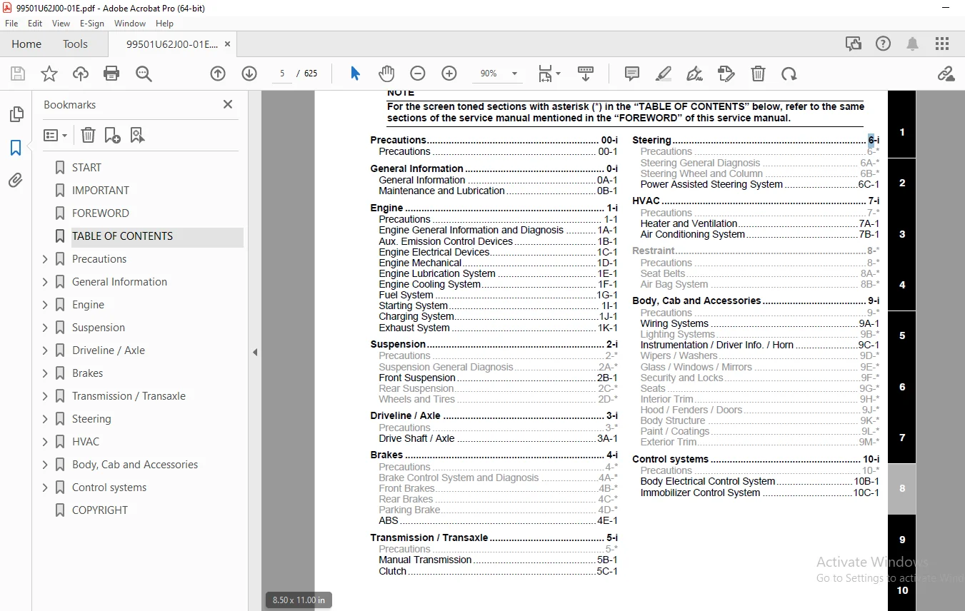
TABLE OF CONTENTS:
SUZUKI SWIFT RS413D SUPPLEMENTARY SERVICE MANUAL – PDF DOWNLOAD
START........................................................................................................  1
IMPORTANT....................................................................................................  1
FOREWORD.....................................................................................................  3
TABLE OF CONTENTS............................................................................................  5
Precautions..................................................................................................  7
	Precautions..............................................................................................  8
		Precautions..........................................................................................  8
			General Precautions..............................................................................  8
General Information.......................................................................................... 11
	General Information...................................................................................... 12
		General Description.................................................................................. 12
			Transmission Identification Number............................................................... 12
		Component Location................................................................................... 12
			Warning, Caution and Information Labels Location................................................. 12
	Maintenance and Lubrication.............................................................................. 14
		Scheduled Maintenance................................................................................ 14
			Maintenance Schedule under Normal Driving Conditions............................................. 14
			Maintenance Recommended under Severe Driving Conditions.......................................... 15
		Repair Instructions.................................................................................. 16
			Engine accessory Drive Belt and Tensioner Inspection............................................. 16
			Engine accessory Drive Belt Replacement.......................................................... 16
			Engine Oil and Filter Change..................................................................... 16
			Engine Coolant Change............................................................................ 18
			Air Cleaner Filter Inspection.................................................................... 18
			Air Cleaner Filter Replacement................................................................... 18
			Fuel Lines and Connections Inspection............................................................ 18
			Fuel Filter Replacement.......................................................................... 18
			Water Draining of Fuel Filter.................................................................... 18
		Specifications....................................................................................... 19
			Tightening Torque Specifications................................................................. 19
		Special Tools and Equipment.......................................................................... 19
			Recommended Fluids and Lubricants................................................................ 19
Engine....................................................................................................... 21
	Precautions.............................................................................................. 25
		Precautions.......................................................................................... 25
			Precautions for Engine........................................................................... 25
	Engine General Information and Diagnosis................................................................. 26
		Precautions.......................................................................................... 26
			Precautions on Engine Service.................................................................... 26
			Precautions in Diagnosing Trouble................................................................ 26
		General Description.................................................................................. 26
			Statement on Cleanliness and Care................................................................ 26
			Engine Diagnosis General Description............................................................. 27
			CAN Communication System Description............................................................. 28
			Electronic Control System Description............................................................ 29
		Schematic and Routing Diagram........................................................................ 33
			Air Intake System Diagram........................................................................ 33
		Component Location................................................................................... 34
			Electronic Control System Components Location.................................................... 34
		Diagnostic Information and Procedures................................................................ 35
			DTC Check........................................................................................ 35
			DTC Clearance.................................................................................... 35
			A: Engine Diagnostic System Check................................................................ 36
			B-01, DTC Table.................................................................................. 38
			B-02, Data List.................................................................................. 41
			B-03, Connect Scan Tool and Establish Communication.............................................. 47
			B-04, Symptom Chart / Customer Complaints........................................................ 47
			B-05, No Matching Customer Complaint............................................................. 47
			B-06, Complaint: Engine Start.................................................................... 48
			B-07, Complaint: Engine Idling................................................................... 48
			B-08, Complaint: Engine Behavior Under Normal Driving Conditions................................. 50
			B-09, Complaint: Engine Performance.............................................................. 52
			B-10, Complaint: Exhaust Gas..................................................................... 54
			B-11, Complaint: Oil / Coolant / Fuel-System..................................................... 55
			B-12, Complaint: Engine Mechanic................................................................. 56
			B-13, Check: Functionality of Adjacent Systems................................................... 56
			B-14, Actuator Test.............................................................................. 57
			B-15, Additional Functions....................................................................... 60
			B-16, Programming................................................................................ 60
			B-17, ECU Control................................................................................ 61
			B-18, Check: Intermittent Faults................................................................. 62
			B-19, Programming ECM............................................................................ 63
			B-20, Immobilizer Check.......................................................................... 63
			B-21, Fuel System................................................................................ 64
			B-22, Intake-Air System.......................................................................... 64
			B-23, Check: Intake-Air System................................................................... 65
			B-24, Check: Intake-Air System / Charge-Air System............................................... 65
			B-25, Check: Charge-Air System................................................................... 66
			B-26, Check: Exhaust System...................................................................... 66
			B-27, Check: Distance Signal..................................................................... 67
			B-28, Check: Pressure Sensor Signal.............................................................. 67
			B-29, Complaint: Engine Temperature.............................................................. 67
			B-30, Check: High Pressure Area.................................................................. 68
			B-31, Check: Low and High Pressure Section....................................................... 69
			B-32, Check: Low Pressure Section................................................................ 69
			B-33, Check: Injectors........................................................................... 70
			B-34, Trouble Codes: Check 1..................................................................... 70
			B-35, Trouble Codes: Check 2..................................................................... 70
			B-36, Trouble Codes: Check 3..................................................................... 71
			B-37, Trouble Codes: Check 4..................................................................... 71
			B-38, Trouble Codes: Check 5..................................................................... 71
			C-01, No Communication between Scan Tool and Control Unit........................................ 72
			C-02, Control Unit Hard- and Software............................................................ 78
			C-03, System Voltage Circuit..................................................................... 79
			C-04, Control Unit Main Relay Circuit............................................................ 80
			C-05, Crankshaft Sensor Circuit.................................................................. 84
			C-06, Fuel Pump Relay Circuit.................................................................... 85
			C-07, 5 V Circuit 1.............................................................................. 88
			C-08, 5 V Circuit 2.............................................................................. 90
			C-09, 5 V Circuit 3.............................................................................. 92
			C-10, Accelerator Pedal Position (APP) Sensor Circuit............................................ 95
			C-11, Barometer Sensor Circuit................................................................... 98
			C-12, Boost Pressure Sensor Circuit.............................................................. 99
			C-13, Intake Air Temperature Sensor Circuit......................................................101
			C-14, Mass or Volume Air Flow Circuit............................................................102
			C-15, Engine Coolant Temperature Sensor Circuit..................................................105
			C-16, Fuel Temperature Sensor Circuit............................................................107
			C-17, Fuel Rail Pressure Sensor Circuit..........................................................109
			C-18, Rail Oil Pressure Sensor Circuit...........................................................111
			C-19, Fuel Rail Pressure Control Valve Circuit...................................................112
			C-20, Camshaft Position Sensor Circuit...........................................................114
			C-21, Brake Switch Circuit.......................................................................116
			C-22, Clutch Switch Circuit......................................................................121
			C-23, Injector Circuit...........................................................................122
			C-24, Cylinder 1 Injector Circuit................................................................122
			C-25, Cylinder 2 Injector Circuit................................................................124
			C-26, Cylinder 3 Injector Circuit................................................................126
			C-27, Cylinder 4 Injector Circuit................................................................128
			C-28, Exhaust Gas Recirculation Valve Circuit....................................................131
			C-29, Air Conditioning System Refrigerant Pressure Sensor........................................133
			C-30, Engine Oil Pressure Switch Circuit.........................................................136
			C-31, Air Conditioning System Relay Circuit......................................................137
			C-32, Fan Circuit................................................................................140
			C-33, Glow Time Relay Circuit....................................................................147
			C-34, CAN Communication Circuit..................................................................150
			C-35, Filter heating Circuit.....................................................................154
			C-36, Malfunction Indicator Lamp (MIL) Circuit...................................................158
			C-37, Vehicle Speed Sensor Circuit...............................................................160
			C-38, Function-Group Intake Air System...........................................................161
			C-39, Function-Group Fuel System.................................................................162
			C-40, Function-Group Low Pressure Section........................................................162
			C-41, Function-Group Low and High Pressure Section...............................................163
			C-42, Function-Group High Pressure Area..........................................................163
			C-43, Starter Circuit............................................................................164
			C-44, System Status Information..................................................................169
		Special Tools and Equipment..........................................................................169
			Special Tool.....................................................................................169
	Aux. Emission Control Devices............................................................................170
		Repair Instructions..................................................................................170
			Vacuum Pump Removal and Installation.............................................................170
			EGR Valve Assembly Components....................................................................171
			EGR Valve Assembly Removal and Installation......................................................172
			Crankcase Ventilation System Component...........................................................173
			Oil Separator and Crankcase Ventilation Cover Removal and Installation...........................173
		Specifications.......................................................................................174
			Tightening Torque Specifications.................................................................174
	Engine Electrical Devices................................................................................175
		Repair Instructions..................................................................................175
			Idle Speed Inspection............................................................................175
			Engine Control Module (ECM) Removal and Installation.............................................175
			ECM Registration.................................................................................175
			Registration Data Check..........................................................................176
			Mass Air Flow (MAF) and Intake Air Temperature Sensor Removal and Installation...................176
			Glow Plug Removal and Installation...............................................................177
			Accelerator Pedal Position (APP) Sensor Components...............................................178
			Accelerator Pedal Position (APP) Sensor Removal and Installation.................................178
			Accelerator Pedal Position (APP) Sensor Inspection...............................................179
			Engine Coolant Temperature (ECT) Sensor Removal and Installation.................................180
			Camshaft Position (CMP) Sensor Removal and Installation..........................................180
			Crankshaft Position (CKP) Sensor (Engine Speed Sensor) Removal and Installation..................181
			Boost Pressure Sensor Removal and Installation...................................................181
			Fuel Pump Relay, Starting Motor Control Relay, Main Relay and Fuel Heating Relay Inspection......182
			Glow Controller Removal and Installation.........................................................182
		Specifications.......................................................................................183
			Tightening Torque Specifications.................................................................183
		Special Tools and Equipment..........................................................................183
			Special Tool.....................................................................................183
	Engine Mechanical........................................................................................184
		Diagnostic Information and Procedures................................................................184
			Compression Check................................................................................184
			Timing Check.....................................................................................185
		Repair Instructions..................................................................................186
			Air Cleaner Components...........................................................................186
			Air Cleaner Filter Removal and Installation......................................................187
			Air Cleaner Filter Inspection and Cleaning.......................................................187
			Air Cleaner Assembly Removal and Installation....................................................187
			Intercooler Components...........................................................................188
			Intercooler Removal and Installation.............................................................189
			Turbocharger Components..........................................................................190
			Turbocharger Removal and Installation............................................................191
			Turbocharger Inspection..........................................................................194
			Intake Manifold Components.......................................................................195
			Intake Manifold Removal and Installation.........................................................195
			Engine Mounting Components.......................................................................197
			Engine Assembly Removal and Installation.........................................................198
			Timing Chain Cover and Timing Chain Components...................................................201
			Timing Chain Cover and Timing Chain Removal and Installation.....................................202
			Timing Chain Cover and Timing Chain Inspection...................................................208
			Camshaft Housing Components......................................................................209
			Camshaft Housing Assembly Removal and Installation...............................................210
			Camshaft Housing Assembly Disassembly and Reassembly.............................................212
			Camshaft Inspection..............................................................................214
			Valves and Cylinder Head Components..............................................................216
			Valves and Cylinder Head Assembly Removal and Installation.......................................217
			Valves and Cylinder Head Assembly Disassembly and Reassembly.....................................220
			Valves and Cylinder Head Components Inspection...................................................222
			Pistons, Piston Rings, Connecting Rods and Cylinder Components...................................223
			Pistons, Piston Rings, Connecting Rods and Cylinder Removal and Installation.....................224
			Pistons, Piston Rings, Connecting Rods and Cylinder Disassembly and Reassembly...................226
			Pistons, Piston Rings, Connecting Rods and Cylinder Inspection...................................227
			Main Bearings, Crankshaft and Cylinder Block Components..........................................230
			Main Bearings, Crankshaft and Cylinder Block Removal and Installation............................231
			Main Bearings, Crankshaft and Cylinder Block Inspection..........................................235
		Specifications.......................................................................................236
			Tightening Torque Specifications.................................................................236
		Special Tools and Equipment..........................................................................238
			Recommended Service Material.....................................................................238
			Special Tool.....................................................................................238
	Engine Lubrication System................................................................................240
		Diagnostic Information and Procedures................................................................240
			Oil Pressure Check...............................................................................240
		Repair Instructions..................................................................................241
			Oil Pressure Switch Removal and Installation.....................................................241
			Oil Cooler Components............................................................................241
			Oil Cooler Removal and Installation..............................................................242
			Oil Pan Components...............................................................................243
			Oil Pan Removal and Installation.................................................................243
			Oil Pump / Oil Pump Strainer Components..........................................................245
			Oil Pump / Oil Pump Strainer Removal and Installation............................................246
			Oil Pump Strainer Cleaning.......................................................................246
			Oil Pump Inspection..............................................................................246
		Specifications.......................................................................................247
			Tightening Torque Specifications.................................................................247
		Special Tools and Equipment..........................................................................247
			Recommended Service Material.....................................................................247
			Special Tool.....................................................................................247
	Engine Cooling System....................................................................................248
		General Description..................................................................................248
			Cooling System Description.......................................................................248
			Coolant Description..............................................................................248
			Coolant Degassing Tank Description...............................................................248
		Schematic and Routing Diagram........................................................................249
			Coolant Circulation..............................................................................249
		Diagnostic Information and Procedures................................................................250
			Engine Cooling Symptom Diagnosis.................................................................250
			Radiator Fan Control System Inspection...........................................................250
		Repair Instructions..................................................................................251
			Cooling System Components........................................................................251
			Coolant Level Check..............................................................................252
			Engine Cooling System Inspection and Cleaning....................................................252
			Cooling System Draining..........................................................................253
			Cooling System Refill............................................................................253
			Cooling System Flush and Refill..................................................................253
			Cooling Water Pipes or Hoses Removal and Installation............................................254
			Thermostat Case Assembly Removal and Installation................................................254
			Radiator Cooling Fan Assembly On-Vehicle Inspection..............................................255
			Radiator Cooling Fan Relay Inspection............................................................255
			Radiator Cooling Fan Assembly Removal and Installation...........................................256
			Radiator On-Vehicle Inspection and Cleaning......................................................256
			Radiator Removal and Installation................................................................257
			Water Pump / Generator Drive Belt Tension Inspection.............................................257
			Water Pump / Generator Drive Belt Removal and Installation.......................................258
			Water Pump / Generator Drive Belt Tensioner Assembly Removal and Installation....................258
			Water Pump Removal and Installation..............................................................259
			Water Pump Inspection............................................................................259
		Specifications.......................................................................................260
			Tightening Torque Specifications.................................................................260
	Fuel System..............................................................................................261
		Precautions..........................................................................................261
			Precautions on Fuel System Service...............................................................261
		General Description..................................................................................263
			Fuel System Description..........................................................................263
		Schematic and Routing Diagram........................................................................264
			Fuel Delivery System Diagram.....................................................................264
		Repair Instructions..................................................................................265
			Fuel Hose Disconnecting and Reconnecting.........................................................265
			Fuel Leakage Check Procedure.....................................................................267
			Water Draining of Fuel Filter....................................................................267
			Air Bleeding of Fuel System......................................................................267
			Fuel Delivery System (High Pressure) Components..................................................268
			Fuel Injector On-Vehicle Inspection..............................................................269
			Fuel Injector Removal and Installation...........................................................269
			Common Rail (High Pressure Fuel Injection Rail) Removal and Installation.........................272
			Injection Pump Removal and Installation..........................................................273
			Fuel Pressure Sensor Removal and Installation....................................................274
			Fuel Pressure Regulator Removal and Installation.................................................275
			Fuel Pressure Regulator Inspection...............................................................275
			Fuel Delivery System (Low Pressure) Components...................................................276
			Fuel Lines On-Vehicle Inspection.................................................................277
			Fuel Pipe Removal and Installation...............................................................277
			Fuel Filler Cap Inspection.......................................................................278
			Fuel Tank Removal and Installation...............................................................278
			Fuel Tank Inspection.............................................................................280
			Fuel Tank Purging Procedure......................................................................281
			Fuel Pump On-Vehicle Inspection..................................................................281
			Fuel Pump Assembly Removal and Installation......................................................281
			Fuel Pump Inspection.............................................................................282
			Fuel Filter Element Removal and Installation.....................................................283
			Fuel Filter Assembly Removal and Installation....................................................284
			Fuel Heater and Temperature Sensor Removal and Installation......................................284
			Fuel Temperature Sensor Inspection...............................................................285
		Specifications.......................................................................................285
			Tightening Torque Specifications.................................................................285
		Special Tools and Equipment..........................................................................286
			Special Tool.....................................................................................286
	Starting System..........................................................................................287
		General Description..................................................................................287
			Cranking System Description......................................................................287
		Schematic and Routing Diagram........................................................................287
			Cranking System Circuit Diagram..................................................................287
		Diagnostic Information and Procedures................................................................288
			Cranking System Symptom Diagnosis................................................................288
			Cranking System Test.............................................................................289
		Repair Instructions..................................................................................290
			Starting Motor Dismounting and Remounting........................................................290
		Specifications.......................................................................................291
			Tightening Torque Specifications.................................................................291
	Charging System..........................................................................................292
		General Description..................................................................................292
			Generator Description............................................................................292
		Diagnostic Information and Procedures................................................................293
			Battery Inspection...............................................................................293
			Generator Symptom Diagnosis......................................................................294
			Generator Test (Undercharged Battery Check)......................................................295
			Generator Test (Overcharged Battery Check).......................................................295
		Repair Instructions..................................................................................296
			Battery Dismounting and Remounting...............................................................296
			Generator Dismounting and Remounting.............................................................296
		Specifications.......................................................................................297
			Charging System Specifications...................................................................297
			Tightening Torque Specifications.................................................................297
	Exhaust System...........................................................................................298
		General Description..................................................................................298
			Exhaust System Description.......................................................................298
		Diagnostic Information and Procedures................................................................298
			Exhaust System Check.............................................................................298
		Repair Instructions..................................................................................299
			Exhaust System Components........................................................................299
			Exhaust Manifold Components......................................................................300
			Exhaust Manifold Removal and Installation........................................................301
			Exhaust Manifold Inspection......................................................................302
			Catalytic Converter Removal and Installation.....................................................302
			Exhaust Pipe and Muffler Removal and Installation................................................302
		Specifications.......................................................................................302
			Tightening Torque Specifications.................................................................302
Suspension...................................................................................................303
	Front Suspension.........................................................................................305
		Repair Instructions..................................................................................305
			Front Suspension Frame, Stabilizer Bar and/or Bushings Removal and Installation..................305
Driveline / Axle.............................................................................................309
	Drive Shaft / Axle.......................................................................................310
		General Description..................................................................................310
			Front Drive Shaft Construction...................................................................310
		Component Location...................................................................................310
			Front Drive Shaft Assembly Components Location...................................................310
		Diagnostic Information and Procedures................................................................311
			Front Drive Shaft Symptom Diagnosis..............................................................311
		Repair Instructions..................................................................................311
			Front Drive Shaft Components.....................................................................311
			Front Drive Shaft Assembly On-Vehicle Inspection.................................................312
			Front Drive Shaft Assembly Removal and Installation..............................................312
			Front Drive Shaft Disassembly and Assembly.......................................................313
			Center Shaft and Center Bearing Support Disassembly and Assembly.................................318
		Specifications.......................................................................................319
			Tightening Torque Specifications.................................................................319
		Special Tools and Equipment..........................................................................319
			Recommended Service Material.....................................................................319
			Special Tool.....................................................................................319
Brakes.......................................................................................................321
	ABS......................................................................................................323
		General Description..................................................................................323
			ABS Hydraulic Unit / Control Module Assembly Description.........................................323
		Schematic and Routing Diagram........................................................................324
			ABS Schematic....................................................................................324
			ABS Wiring Circuit Diagram.......................................................................325
		Diagnostic Information and Procedures................................................................327
			Serial Data Link Circuit Check...................................................................327
		Repair Instructions..................................................................................329
			Rear Wheel Speed Sensor Removal and Installation.................................................329
			Vehicle Speed Output Signal Inspection...........................................................330
Transmission / Transaxle.....................................................................................331
	Manual Transmission......................................................................................332
		General Description..................................................................................332
			Manual Transaxle Construction and Servicing......................................................332
		Diagnostic Information and Procedures................................................................334
			Manual Transaxle Symptom Diagnosis...............................................................334
		Repair Instructions..................................................................................335
			Manual Transaxle Oil Change......................................................................335
			Differential Side Oil Seal Replacement...........................................................336
			Gear Shift Control Lever and Cable Components....................................................337
			Gear Shift Control Lever and Cable Removal and Installation......................................338
			Back Up Lamp Switch Removal and Installation.....................................................339
			Back Up Lamp Switch Inspection...................................................................339
			Manual Transaxle Unit Components.................................................................340
			Manual Transaxle Unit Dismounting and Remounting.................................................341
			Manual Transaxle Assembly Components.............................................................343
			Selector Lever Assembly Removal and Installation.................................................344
			5th Gears Removal and Installation...............................................................345
			Gear Selector, Cluster Gear and Main Shaft Components............................................347
			Gear Selector, Cluster Gear and Main Shaft Removal and Installation..............................348
			Transaxle Case Disassembly and Assembly..........................................................352
			Counter Gear and Main Shaft Components...........................................................355
			Main Shaft Disassembly and Assembly..............................................................356
			Cluster Gear and Main Shaft Inspection...........................................................358
			Differential Components..........................................................................359
			Differential Disassembly and Assembly............................................................359
			Differential Adjustment..........................................................................361
		Specifications.......................................................................................362
			Tightening Torque Specifications.................................................................362
		Special Tools and Equipment..........................................................................363
			Recommended Service Material.....................................................................363
			Special Tool.....................................................................................363
	Clutch...................................................................................................366
		General Description..................................................................................366
			Clutch (Hydraulic Type) Construction.............................................................366
		Diagnostic Information and Procedures................................................................367
			Clutch System Symptom Diagnosis..................................................................367
		Repair Instructions..................................................................................368
			Clutch Pedal Inspection..........................................................................368
			Clutch Fluid Level Inspection....................................................................368
			Air Bleeding of Clutch System....................................................................368
			Clutch Fluid Pipe and Hose Location..............................................................369
			Clutch Fluid Pipe Removal and Installation.......................................................369
			Clutch Fluid Pipe Inspection.....................................................................369
			Clutch Master Cylinder Removal and Installation..................................................370
			Clutch Operating Cylinder Assembly Removal and Installation......................................370
			Clutch Pedal and Clutch Pedal Bracket Components.................................................372
			Clutch Cover and Clutch Disc Components..........................................................373
			Clutch Cover and Clutch Disc Removal and Installation............................................373
			Clutch Cover and Clutch Disc Inspection..........................................................375
		Specifications.......................................................................................375
			Tightening Torque Specifications.................................................................375
		Special Tools and Equipment..........................................................................376
			Recommended Service Material.....................................................................376
			Special Tool.....................................................................................376
Steering.....................................................................................................377
	Power Assisted Steering System...........................................................................379
		General Description..................................................................................379
			P/S System Description...........................................................................379
		Schematic and Routing Diagram........................................................................380
			EPS System Wiring Circuit Diagram................................................................380
		Diagnostic Information and Procedures................................................................381
			DTC Table........................................................................................381
			Scan Tool Data...................................................................................383
			P/S System Symptom Diagnosis.....................................................................384
			Serial Data Link Circuit Check...................................................................384
			DTC C1121 / C1123 / C1124: VSS Circuit Failure...................................................386
			DTC C1122: Engine Speed Signal Circuit Failure...................................................388
			Inspection of P/S Control Module and Its Circuits................................................389
		Specifications.......................................................................................391
			Tightening Torque Specifications.................................................................391
		Special Tools and Equipment..........................................................................392
			Recommended Service Material.....................................................................392
			Special Tool.....................................................................................392
HVAC.........................................................................................................393
	Heater and Ventilation...................................................................................395
		General Description..................................................................................395
			Heater and Ventilation Construction..............................................................395
			Supplementary Heater System Description (If Equipped)............................................396
			Supplementary Heater System Components Location..................................................396
			Supplementary Heater System Electronic Input / Output Table......................................397
			On-Board Diagnostic System Description (Vehicle Equipped with Supplementary Heater)..............397
		Schematic and Routing Diagram........................................................................398
			Heater and Ventilation Wiring Circuit Diagram....................................................398
		Diagnostic Information and Procedures................................................................399
			Heater and Ventilation Symptom Diagnosis.........................................................399
			DTC Check for Supplementary Heater System........................................................400
			DTC Clearance for Supplementary Heater System....................................................400
			DTC Table for Supplementary Heater System........................................................400
			Scan Tool Data...................................................................................401
			DTC B1536: Supplementary Heater Relay No.1 Output Malfunction....................................402
			DTC B1537: Supplementary Heater Relay No.2 and No.3 Output Malfunction...........................403
			DTC B1541: Supplementary Heater Controller Back-Up Power Supply Malfunction......................404
			DTC B1542: Blower Motor Power Supply Malfunction.................................................405
			DTC B1551: Serial Communication Circuit Malfunction..............................................407
			DTC B1552: Serial Communication Data Malfunction.................................................408
			DTC B1553: CAN Communication Circuit Malfunction.................................................408
			DTC B1556: Engine Speed Data Malfunction.........................................................409
			DTC B1557: Vehicle Speed Data Malfunction........................................................409
			DTC B1559: Ignition Power Supply Voltage Data Malfunction........................................409
			DTC B1561: Engine Coolant Temperature Data Malfunction...........................................410
			DTC B1562: Outside Air Temperature Data Malfunction..............................................410
			Inspection of Supplementary Heater Controller and Its Circuit (If Equipped)......................411
		Repair Instructions..................................................................................413
			HVAC Unit Components.............................................................................413
			Blower Motor Resistor Inspection.................................................................414
			Blower Motor Relay and Supplementary Heater Relay (If Equipped) Inspection.......................414
			Supplementary Heater Removal and Installation (If Equipped)......................................415
			Supplementary Heater Inspection (If Equipped)....................................................415
			Supplementary Heater Controller Removal and Installation (If Equipped)...........................416
			Max Hot Switch Removal and Installation (If Equipped)............................................416
			Max Hot Switch Inspection (If Equipped)..........................................................416
			Air Intake Control Actuator Removal and Installation.............................................417
		Specifications.......................................................................................417
			Tightening Torque Specifications.................................................................417
		Special Tools and Equipment..........................................................................417
			Special Tool.....................................................................................417
	Air Conditioning System..................................................................................418
		Precautions..........................................................................................418
			Precautions on Servicing A/C System..............................................................418
		General Description..................................................................................419
			Sub-Cool A/C System Description..................................................................419
			A/C Operation Description........................................................................420
		Schematic and Routing Diagram........................................................................420
			A/C System Wiring Diagram........................................................................420
		Diagnostic Information and Procedures................................................................422
			A/C System Symptom Diagnosis.....................................................................422
			Abnormal Noise Symptom Diagnosis of A/C System...................................................424
			A/C System Performance Inspection................................................................425
		Repair Instructions..................................................................................430
			Operation Procedure for Refrigerant Charge.......................................................430
			Desiccant Removal and Installation...............................................................435
			HVAC Unit Components.............................................................................436
			HVAC Unit Removal and Installation...............................................................437
			Compressor Relay Inspection......................................................................438
			Compressor Drive Belt Inspection and Adjustment..................................................438
			Compressor Drive Belt Removal and Installation...................................................438
			Compressor Assembly Removal and Installation.....................................................438
			Magnet Clutch Inspection.........................................................................439
			Relief Valve Inspection..........................................................................439
		Specifications.......................................................................................439
			Tightening Torque Specifications.................................................................439
		Special Tools and Equipment..........................................................................440
			Recommended Service Material.....................................................................440
			Special Tool.....................................................................................440
Body, Cab and Accessories....................................................................................441
	Wiring Systems...........................................................................................446
		Precautions..........................................................................................446
			Cautions in Body Electrical System Servicing.....................................................446
			Precautions for Wiring System....................................................................446
		General Description..................................................................................447
			Abbreviations....................................................................................447
			Wire / Connector Color Symbols...................................................................447
			Symbols and Marks................................................................................448
			How to Read Connector Layout Diagram.............................................................449
			How to Read Connector Codes and Terminal Nos.....................................................450
			How to Read Ground Point.........................................................................453
			How to Read Power Supply Diagram.................................................................454
			How to Read System Circuit Diagram...............................................................454
		Harness Routing and Connector Layout Diagram.........................................................456
			Connector Layout Diagram.........................................................................456
			Engine Compartment...............................................................................456
			E: Main harness (RHD) (DSL)......................................................................462
			E: Main harness (LHD) (DSL)......................................................................463
			Instrument Panel.................................................................................464
			Door, Roof.......................................................................................468
			Floor............................................................................................470
			Rear.............................................................................................478
		Ground Point.........................................................................................479
			Ground (earth) Point.............................................................................479
		Power Supply Diagram.................................................................................480
			Power Supply Diagram (Petrol)....................................................................480
			Power Supply Diagram (DSL).......................................................................481
			Fuses and the Protected Parts....................................................................482
			Fuses in Main Fuse Box (Petrol)..................................................................482
			Fuses in Main Fuse Box (DSL).....................................................................482
			Individual Circuit Fuse Box No. 1 (Petrol).......................................................483
			Individual Circuit Fuse Box No. 1 (DSL)..........................................................483
			Individual Circuit Fuse Box No. 3 (DSL)..........................................................484
			Individual Circuit Fuse Box No. 2 (In J/B).......................................................485
			Junction Block (J/B) Connector / Fuse Layout.....................................................487
			Junction Block Inner Circuit (Overview)..........................................................489
			Junction Block Inner Circuit (Detail)............................................................490
		System Circuit Diagram...............................................................................495
			System Circuit Diagram...........................................................................495
			A-1 Cranking System Circuit Diagram (Petrol).....................................................496
			A-1 Cranking System Circuit Diagram (DSL)........................................................497
			A-2 Charging System Circuit Diagram (Petrol).....................................................498
			A-2 Charging System Circuit Diagram (DSL)........................................................499
			A-3 Ignition System Circuit Diagram (Petrol).....................................................500
			A-4 Cooling System Circuit Diagram (Petrol)......................................................501
			A-4 Cooling System Circuit Diagram (DSL).........................................................502
			A-5 Engine and A/C Control System Circuit Diagram (Petrol).......................................503
			A-5 Engine and A/C Control System (DSL)..........................................................508
			A-6 A/T Control System Circuit Diagram...........................................................513
			A-7 Immobilizer System Circuit Diagram (Petrol)..................................................515
			A-7 Immobilizer System Circuit Diagram (DSL).....................................................516
			A-8 Body Control System Circuit Diagram..........................................................517
			A-9 Automated Manual Transaxle Control System Circuit Diagram (Petrol)...........................521
			B-1 Windshield Wiper and Washer Circuit Diagram..................................................524
			B-2 Rear Wiper and Washer Circuit Diagram........................................................525
			B-3 Rear Defogger Circuit Diagram................................................................526
			B-4 Power Window Circuit Diagram.................................................................527
			B-5 Power Door Lock Circuit Diagram..............................................................528
			B-6 Power Mirror Circuit Diagram.................................................................530
			B-7 Horn Circuit Diagram.........................................................................531
			B-8 Seat Heater Circuit Diagram..................................................................532
			B-9 Smart Key System Circuit Diagram.............................................................533
			C-1 Combination Meter Circuit Diagram (Meter)....................................................534
			C-2 Combination Meter Circuit Diagram (Indicator)................................................535
			C-3 Combination Meter Circuit Diagram (Warning Light)............................................536
			D-1 Headlight System Circuit Diagram.............................................................538
			D-2 Position, Tail and Licence Plate Light System Circuit Diagram................................540
			D-3 Front Fog Light System Circuit Diagram.......................................................541
			D-4 Illumination Light System Circuit Diagram....................................................542
			D-5 Interior Light System Circuit Diagram........................................................543
			D-6 Turn Signal and Hazard Warning Light System Circuit Diagram..................................544
			D-7 Brake Light System Circuit Diagram...........................................................546
			D-8 Back-Up Light System Circuit Diagram.........................................................547
			D-9 Headlight Beam Leveling System Circuit Diagram...............................................548
			D-10 Rear Fog Light Circuit Diagram..............................................................549
			E-1 Heater System Circuit Diagram................................................................550
			E-3 PTC Heater Circuit Diagram (DSL).............................................................552
			F-1 Air-Bag System Circuit Diagram...............................................................554
			F-2 Anti-Lock Brake System Circuit Diagram.......................................................556
			F-3 Power Steering System Circuit Diagram........................................................558
			G-1 Audio System Circuit Diagram.................................................................560
			G-2 Multi Information Display / Accessory Socket System Circuit Diagram..........................561
			G-4 Navigation System Circuit Diagram............................................................562
		List of Connectors...................................................................................563
			List of Connectors...............................................................................563
			C Connector......................................................................................563
			D Connector (DSL)................................................................................564
			E Connector......................................................................................565
			G Connector......................................................................................567
			J Connector......................................................................................569
			K Connector......................................................................................569
			L Connector......................................................................................570
			O Connector......................................................................................572
			R Connector......................................................................................572
	Instrumentation / Driver Info. / Horn....................................................................573
		General Description..................................................................................573
			CAN Communication Data of Combination Meter......................................................573
		Schematic and Routing Diagram........................................................................574
			Combination Meter Circuit Diagram................................................................574
		Diagnostic Information and Procedures................................................................575
			Speedometer and VSS Symptom Diagnosis............................................................575
			Information Display Symptom Diagnosis (If Equipped)..............................................576
		Repair Instructions..................................................................................577
			Oil Pressure Switch Removal and Installation.....................................................577
			Oil Pressure Switch Inspection...................................................................577
			VSS Removal and Installation.....................................................................577
			VSS Inspection...................................................................................577
Control systems..............................................................................................579
	Body Electrical Control System...........................................................................581
		General Description..................................................................................581
			CAN Communication System Description.............................................................581
		Schematic and Routing Diagram........................................................................582
			Body Electrical Control System Wiring Circuit Diagram............................................582
		Component Location...................................................................................585
			BCM and Related System Component Location........................................................585
		Diagnostic Information and Procedures................................................................586
			BCM Self-Diagnosis Function......................................................................586
			Scan Tool Data...................................................................................587
			DTC Table........................................................................................589
			DTC B1133 (DTC No. 1133): Battery Voltage Too High...............................................590
			DTC U1001 (No. 1001): High Speed CAN Communication (Transmission Error)..........................591
			DTC U1073 (No. 1073): Control Module Communication Bus Off.......................................593
			DTC U1100 (No. 1100): Lost communication with ECM................................................595
			Inspection of BCM and its Circuits...............................................................596
	Immobilizer Control System...............................................................................605
		Precautions..........................................................................................605
			Precautions in Diagnosing Troubles...............................................................605
			Precautions in Handling Immobilizer Control System...............................................605
		General Description..................................................................................606
			Immobilizer Control System Operation Description.................................................606
			Immobilizer Control System Components Description................................................606
			On-Board Diagnostic System Description...........................................................607
		Schematic and Routing Diagram........................................................................608
			Immobilizer Control System Wiring Circuit Diagram................................................608
		Diagnostic Information and Procedures................................................................609
			Immobilizer Control System Check.................................................................609
			DTC Check........................................................................................609
			DTC Clearance....................................................................................610
			DTC Table........................................................................................610
			Scan Tool Data...................................................................................611
			SVS Lamp Does Not Come ON with Ignition Switch ON and Engine Stop................................612
			SVS Lamp Remains On after Ignition Switch ON.....................................................614
			DTC B3040: W-Line Communication Failure..........................................................614
			DTC B3042: W-Line Circuit Malfunction Shorted to Ground..........................................615
			DTC B3043: W-Line Circuit Malfunction Shorted to Battery.........................................615
			DTC B3055: No Transponder........................................................................616
			DTC B3056: No Fix Code Registered................................................................617
			DTC B3057: No Password Registered................................................................617
			DTC B3059: No Request from ECM...................................................................618
			DTC B3060: Incorrect Transponder Detected........................................................618
			DTC B3061: Transponder Communication Failure.....................................................619
			DTC P1610: Secret Key / Password Not Programed...................................................619
			DTC P1611: Password Is Not Matched...............................................................620
			DTC P1612 / P1613: No Signal from Immobilizer Control Module / Immobilizer System Malfunction....620
			DTC P1614: Incorrect Signal from Immobilizer Control Module......................................621
			Registration Procedure of Immobilizer Control System Components..................................621
			Inspection of Immobilizer Control Module and Its Circuit.........................................622
		Repair Instructions..................................................................................623
			Immobilizer Control Module Removal and Installation..............................................623
			Procedure after Immobilizer Control Module Replacement...........................................623
			Procedure after ECM Replacement..................................................................623
		Special Tools and Equipment..........................................................................624
			Special Tool.....................................................................................624
COPYRIGHT....................................................................................................625
S.S