Trusted Business
Verified & Licensed
Virus Free Files
100% Safe Downloads
Secure Payment
SSL Protected
Instant Delivery
Available Immediately
Suzuki SX4 RW416 RW419D Electronic Stability Program Model Supplementary Service Manual – PDF DOWNLOAD
$19.95
Suzuki SX4 RW416 RW419D Electronic Stability Program Model Supplementary Service Manual – PDF DOWNLOAD
Instant PDF Download
Available immediately
Save to Your Device
Download & keep forever
Antivirus Scanned
100% virus-free
Trusted Worldwide
175,000+ customers
Description
Suzuki SX4 RW416 RW419D Electronic Stability Program Model Supplementary Service Manual – PDF DOWNLOAD
FILE DETAILS:
Suzuki SX4 RW416 RW419D Electronic Stability Program Model Supplementary Service Manual – PDF DOWNLOAD
Language : English
Pages : 78
Downloadable : Yes
File Type : PDF
IMAGES PREVIEW OF THE MANUAL:
TABLE OF CONTENTS:
Suzuki SX4 RW416 RW419D Electronic Stability Program Model Supplementary Service Manual – PDF DOWNLOAD
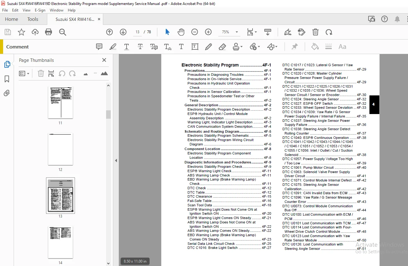
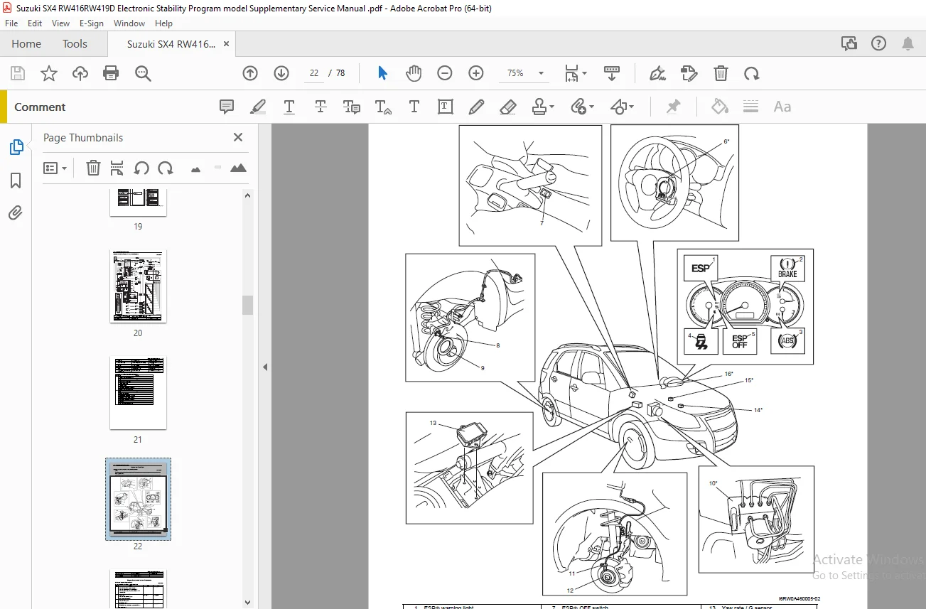
START..................................................................................................................................................... 1
IMPORTANT................................................................................................................................................. 1
FOREWORD.................................................................................................................................................. 3
TABLE OF CONTENTS......................................................................................................................................... 5
Precautions............................................................................................................................................... 7
	Precautions........................................................................................................................................... 8
		Precautions....................................................................................................................................... 8
			General Precautions........................................................................................................................... 8
			Precaution for Vehicle Equipped with ESP‚ System..............................................................................................11
			Brake Caution.................................................................................................................................11
Brakes....................................................................................................................................................13
	Electronic Stability Program..........................................................................................................................15
		Precautions.......................................................................................................................................15
			Precautions in Diagnosing Troubles............................................................................................................15
			Precautions in On-Vehicle Service.............................................................................................................15
			Precautions in Hydraulic Unit Operation Check.................................................................................................15
			Precautions in Sensor Calibration.............................................................................................................15
			Precautions in Speedometer Test or Other Tests................................................................................................16
		General Description...............................................................................................................................16
			Electronic Stability Program Description......................................................................................................16
			ESP‚ Hydraulic Unit / Control Module Assembly Description.....................................................................................16
			Warning Light, Indicator Light Description....................................................................................................17
			CAN Communication System Description..........................................................................................................18
		Schematic and Routing Diagram.....................................................................................................................19
			Electronic Stability Program Schematic........................................................................................................19
			Electronic Stability Program Wiring Circuit Diagram...........................................................................................20
		Component Location................................................................................................................................22
			Electronic Stability Program Component Location...............................................................................................22
		Diagnostic Information and Procedures.............................................................................................................23
			Electronic Stability Program Check............................................................................................................23
			ESP‚ Warning Light Check......................................................................................................................25
			ABS Warning Lamp Check........................................................................................................................25
			EBD Warning Lamp (Brake Warning Lamp) Check...................................................................................................25
			DTC Check.....................................................................................................................................26
			DTC Table.....................................................................................................................................26
			DTC Clearance.................................................................................................................................29
			Fail-Safe Table...............................................................................................................................30
			Scan Tool Data................................................................................................................................32
			ESP‚ Warning Light Does Not Come ON at Ignition Switch ON.....................................................................................34
			ESP‚ Warning Light Comes ON Steady............................................................................................................35
			ABS Warning Lamp Does Not Come ON at Ignition Switch ON.......................................................................................36
			ABS Warning Lamp Comes ON Steady..............................................................................................................36
			EBD Warning Lamp (Brake Warning Lamp) Comes ON Steady.........................................................................................37
			Serial Data Link Circuit Check................................................................................................................39
			DTC C1016: Brake Light Switch.................................................................................................................41
			DTC C1017 / C1023: Lateral G Sensor / Yaw Rate Sensor.........................................................................................43
			DTC C1020 / C1028: Master Cylinder Pressure Sensor Power Supply Failure / Circuit.............................................................43
			DTC C1021 / C1022 / C1025 / C1026 / C1031 / C1032 / C1035 / C1036: Wheel Speed Sensor Circuit / Sensor or Encoder.............................44
			DTC C1024: Steering Angle Sensor..............................................................................................................46
			DTC C1027: ESP‚ OFF Switch....................................................................................................................46
			DTC C1033: Wheel Speed Sensor Deviation.......................................................................................................47
			DTC C1034 / C1039: Yaw Rate / G Sensor Power Supply Failure / Internal Failure................................................................49
			DTC C1037: Steering Angle Sensor Power Supply Failure.........................................................................................50
			DTC C1038: Steering Angle Sensor Detect Rolling Counter.......................................................................................51
			DTC C1040: ESP‚ Continuous Operation..........................................................................................................52
			DTC C1041 / C1042 / C1043 / C1044 / C1045 / C1046 / C1051 / C1052 / C1053 / C1054 / C1055 / C1056: Inlet / Outlet / Cut / Suction Solenoid....52
			DTC C1057: Power Supply Voltage Too High / Too Low............................................................................................53
			DTC C1061: Pump Motor Circuit.................................................................................................................54
			DTC C1063: Solenoid Valve Power Supply Driver Circuit.........................................................................................55
			DTC C1071: Control Module Internal Defect.....................................................................................................56
			DTC C1075: Steering Angle Sensor Calibration..................................................................................................56
			DTC C1091: CAN Invalid Data from ECM..........................................................................................................57
			DTC C1096: Yaw Rate / G Sensor Message Counter Error..........................................................................................57
			DTC U0073: Control Module Communication Bus Off...............................................................................................58
			DTC U0100: Lost Communication with ECM / PCM..................................................................................................60
			DTC U0101 Lost Communication with TCM.........................................................................................................61
			DTC U0114 Lost Communication with Four-Wheel Drive Clutch Control Module......................................................................62
			DTC U0123 Lost Communication with Yaw Rate Sensor Module......................................................................................64
			DTC U0126: Lost Communication with Steering Angle Sensor......................................................................................65
			ESP‚ Hydraulic Unit / Control Module Assembly Power and Ground Circuit Check..................................................................67
		Repair Instructions...............................................................................................................................68
			ESP‚ Hydraulic Unit Operation Check...........................................................................................................68
			Sensor Calibration............................................................................................................................69
			ESP‚ Hydraulic unit / control module Assembly On-Vehicle Inspection...........................................................................69
			ESP‚ Hydraulic unit / control module Assembly Removal and Installation........................................................................70
			Front Wheel Speed Sensor On-Vehicle Inspection................................................................................................72
			Front Wheel Speed Sensor Removal and Installation.............................................................................................72
			Front Wheel Speed Sensor Inspection...........................................................................................................72
			Rear Wheel Speed Sensor On-Vehicle Inspection.................................................................................................72
			Rear Wheel Speed Sensor Removal and Installation..............................................................................................72
			Rear Wheel Speed Sensor Inspection............................................................................................................72
			Front Wheel Speed Sensor Encoder On-Vehicle Inspection........................................................................................72
			Front Wheel Speed Sensor Encoder Removal and Installation.....................................................................................72
			Rear Wheel Speed Sensor Encoder On-Vehicle Inspection.........................................................................................72
			Rear Wheel Speed Sensor Encoder Removal and Installation......................................................................................72
			Master Cylinder Pressure Sensor On-Vehicle Inspection.........................................................................................72
			Yaw Rate / G Sensor On-Vehicle Inspection.....................................................................................................73
			Yaw Rate / G Sensor Removal and Installation..................................................................................................74
			Yaw Rate / G Sensor Inspection................................................................................................................75
			Steering Angle Sensor On-Vehicle Inspection...................................................................................................75
			Steering Angle Sensor Removal and Installation................................................................................................75
			Steering Angle Sensor Inspection..............................................................................................................75
			ESP‚ OFF Switch Removal and Installation......................................................................................................76
			ESP‚ OFF Switch Inspection....................................................................................................................76
		Specifications....................................................................................................................................76
			Tightening Torque Specifications..............................................................................................................76
		Special Tools and Equipment.......................................................................................................................77
			Special Tool..................................................................................................................................77
COPYRIGHT.................................................................................................................................................78
S.S