Trusted Business
Verified & Licensed
Virus Free Files
100% Safe Downloads
Secure Payment
SSL Protected
Instant Delivery
Available Immediately
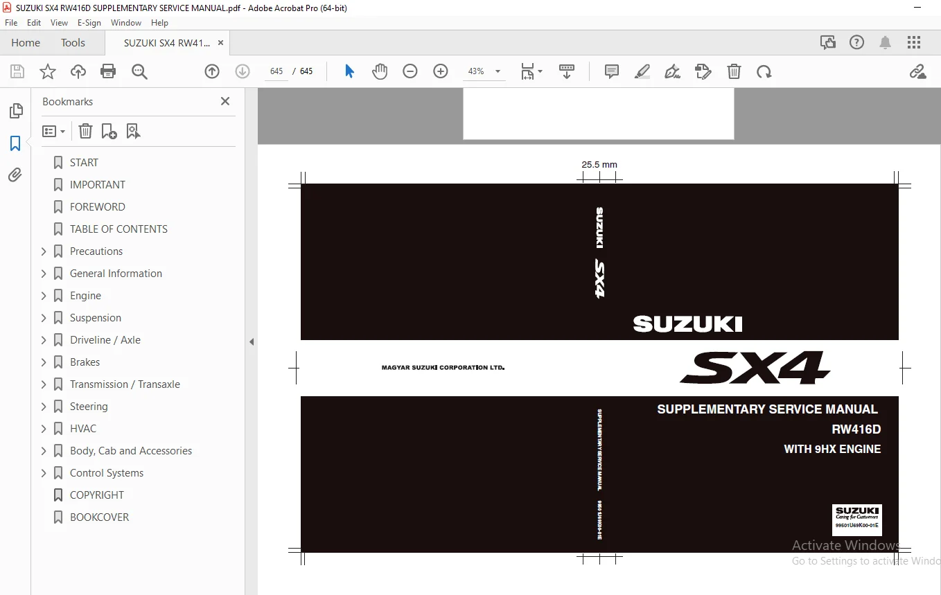
SUZUKI SX4 RW416D SUPPLEMENTARY SERVICE MANUAL – PDF DOWNLOAD
$30.95
SUZUKI SX4 RW416D SUPPLEMENTARY SERVICE MANUAL – PDF DOWNLOAD
Instant PDF Download
Available immediately
Save to Your Device
Download & keep forever
Antivirus Scanned
100% virus-free
Trusted Worldwide
175,000+ customers
Description
SUZUKI SX4 RW416D SUPPLEMENTARY SERVICE MANUAL – PDF DOWNLOAD
FILE DETAILS:
SUZUKI SX4 RW416D SUPPLEMENTARY SERVICE MANUAL – PDF DOWNLOAD
Language : English
Pages : 645
Downloadable : Yes
File Type : PDF
IMAGES PREVIEW OF THE MANUAL:
TABLE OF CONTENTS:
SUZUKI SX4 RW416D SUPPLEMENTARY SERVICE MANUAL – PDF DOWNLOAD
START
....................................................................................................................................................  5
IMPORTANT
................................................................................................................................................  1
FOREWORD
.................................................................................................................................................  3
TABLE OF CONTENTS.........................................................................................................................................  5
Precautions...............................................................................................................................................  7
	Precautions...........................................................................................................................................  8
		Precautions.......................................................................................................................................  8
			General Precautions...........................................................................................................................  8
			Precaution for Vehicle Equipped with ESP‚ System.............................................................................................. 11
			Precautions for Catalytic Converter........................................................................................................... 11
General Information....................................................................................................................................... 13
	General Information................................................................................................................................... 14
		General Description............................................................................................................................... 14
			Abbreviations................................................................................................................................. 14
			Engine Identification Number.................................................................................................................. 15
		Component Location................................................................................................................................ 15
			Warning, Caution and Information Labels Location.............................................................................................. 15
	Maintenance and Lubrication........................................................................................................................... 17
		Scheduled Maintenance............................................................................................................................. 17
			Maintenance Schedule under Normal Driving Conditions.......................................................................................... 17
			Maintenance Recommended under Severe Driving Conditions....................................................................................... 18
		Repair Instructions............................................................................................................................... 19
			Accessory Drive Belt Inspection............................................................................................................... 19
			Camshaft Timing Belt Replacement.............................................................................................................. 19
			Engine Oil and Oil Filter Change.............................................................................................................. 19
			Engine Coolant Inspection..................................................................................................................... 21
			Engine Coolant Change......................................................................................................................... 21
			Exhaust System Inspection..................................................................................................................... 21
			Air Cleaner Filter Inspection................................................................................................................. 21
			Air Cleaner Filter Replacement................................................................................................................ 21
			Fuel Filter Replacement....................................................................................................................... 21
			Water Draining of Fuel Filter................................................................................................................. 21
			Clutch Fluid Inspection....................................................................................................................... 22
		Specifications.................................................................................................................................... 22
			Tightening Torque Specifications.............................................................................................................. 22
		Special Tools and Equipment....................................................................................................................... 22
			Recommended Fluids and Lubricants............................................................................................................. 22
Engine.................................................................................................................................................... 23
	Precautions........................................................................................................................................... 28
		Precautions....................................................................................................................................... 28
			Precautions for Engine........................................................................................................................ 28
	Engine General Information and Diagnosis.............................................................................................................. 29
		Precautions....................................................................................................................................... 29
			Precautions on Engine Service................................................................................................................. 29
			Precautions in Diagnosing Trouble............................................................................................................. 29
			Statement on Cleanliness and Care............................................................................................................. 30
		General Description............................................................................................................................... 30
			Engine Diagnosis General Description.......................................................................................................... 30
			OBD System Description........................................................................................................................ 30
			CAN Communication System Description.......................................................................................................... 32
			Electronic Control System Description......................................................................................................... 33
		Component Location................................................................................................................................ 38
			Electronic Control System Components Location................................................................................................. 38
		Diagnostic Information and Procedures............................................................................................................. 39
			Malfunction Indicator Lamp (MIL) Check........................................................................................................ 39
			Service Vehicle Soon (SVS) Light Check........................................................................................................ 39
			Engine and Emission Control System Check...................................................................................................... 40
			DTC Check..................................................................................................................................... 42
			DTC Clearance................................................................................................................................. 42
			DTC Confirmation Procedure.................................................................................................................... 43
			DTC Table..................................................................................................................................... 43
			Scan Tool Data................................................................................................................................ 49
			Visual Inspection............................................................................................................................. 53
			Engine Basic Inspection....................................................................................................................... 54
			Engine Symptom Diagnosis...................................................................................................................... 54
			DTC P0001 / P0003 / P0004: Fuel Flow Actuator Control Circuit Open / Low / High............................................................... 73
			DTC P0002: Fuel Flow Actuator Control Circuit Range / Performance............................................................................. 74
			DTC P0016: Crankshaft Position - Camshaft Position Correlation................................................................................ 74
			DTC P0069: Boost Pressure - Barometric Pressure Correlation................................................................................... 76
			DTC P0087 / P0088: Fuel Rail Pressure - Too Low / High........................................................................................ 77
			DTC P0093: Fuel System Large Leak Detected.................................................................................................... 77
			DTC P0097 / P0098: IAT Sensor-2 Circuit Low / High............................................................................................ 78
			DTC P0100: MAF Circuit........................................................................................................................ 79
			DTC P0102 / P0103 / P0104: MAF Circuit Low Input / High Input / Intermittent.................................................................. 79
			DTC P0107 / P0108: Barometric Pressure Circuit Low / High Input............................................................................... 81
			DTC P0112 / P0113: IAT Sensor-1 Circuit Low / High............................................................................................ 81
			DTC P0115 / P0116: ECT Circuit Range / Performance............................................................................................ 82
			DTC P0117 / P0118: ECT Circuit Low / High..................................................................................................... 84
			DTC P0120 / P0121: Inlet Throttle Valve Position Sensor Circuit / Range / Performance......................................................... 84
			DTC P0122 / P0123: Inlet Throttle Valve Position Sensor Circuit Low / High.................................................................... 85
			DTC P0182 / P0183: Fuel Temperature Sensor Circuit Low / High................................................................................. 86
			DTC P0192 / P0193: Fuel Pressure Sensor Circuit Low / High.................................................................................... 87
			DTC P0201 / P0202 / P0203 / P0204: Injector Circuit / Open - Cylinder 1 / Cylinder 2 / Cylinder 3 / Cylinder 4................................ 88
			DTC P0215: Double Relay Circuit Malfunction................................................................................................... 89
			DTC P0222 / P0223: APP Sensor (Main) Circuit Low / High....................................................................................... 90
			DTC P0227 / P0228: APP Sensor (Sub) Circuit Low / High........................................................................................ 90
			DTC P0234 / P0299: Turbocharger Overboost Condition / Underboost Condition.................................................................... 90
			DTC P0237 / P0238: Boost Pressure Sensor Circuit Low / High................................................................................... 92
			DTC P0243 / P0245 / P0246: Boost Pressure Control Solenoid Valve Circuit / Low / High......................................................... 93
			DTC P0262 / P0265 / P0268 / P0271: Cylinder 1 / Cylinder 2 / Cylinder 3 / Cylinder 4 Injector Circuit High.................................... 94
			DTC P0335 / P0339: CKP Sensor Circuit / Intermittent.......................................................................................... 95
			DTC P0341 / P0344: CMP Sensor Circuit Range / Performance / Malfunction....................................................................... 96
			DTC P0401 / P0402: EGR Flow Insufficient Detected / Excessive Detected........................................................................ 97
			DTC P0405 / P0406: EGR Position Sensor Circuit Low / High..................................................................................... 98
			DTC P0409: EGR Position Sensor Circuit........................................................................................................ 99
			DTC P0483 / P0494: Fan Rationality Check / Fan Speed Low......................................................................................100
			DTC P0487 / P0488: Inlet Throttle Valve Control Circuit Range / Performance...................................................................101
			DTC P0489 / P0490: EGR Control Circuit Low / High.............................................................................................102
			DTC P0500: Vehicle Speed Sensor...............................................................................................................103
			DTC P0532 / P0533: A/C Refrigerant Pressure Sensor Circuit Low / High.........................................................................103
			DTC P0562 / P0563: System Voltage Low / High..................................................................................................105
			DTC P0603: Internal Control Module Keep Alive Memory (KAM) Error..............................................................................105
			DTC P0606: ECM Processor......................................................................................................................106
			DTC P0650 / P1642: Malfunction Indicator Lamp (MIL) Control Circuit / Open....................................................................106
			DTC P0658 / P0659: Sensor Power Supply Circuit 1 Low / High...................................................................................108
			DTC P0686 / P0687 / P1639 / P1640: Double Relay Control Circuit Low / High / Open / Range / Performance.......................................110
			DTC P0691 / P0692: Radiator Cooling Fan Relay No.1 Control Circuit Low / High.................................................................111
			DTC P0693 / P0694: Radiator Cooling Fan Relay No.2 and No.3 Control Circuit Low / High........................................................112
			DTC P0695 / P0696: Radiator Cooling Sub Fan Control Circuit Low / High........................................................................114
			DTC P0704: CPP Switch Signal Circuit Malfunction..............................................................................................115
			DTC P1113 / P1166: Fuel Pressure Too Low / High...............................................................................................116
			DTC P1161: Inlet Throttle Valve Stuck On......................................................................................................116
			DTC P1162: EGR Valve Stuck On.................................................................................................................117
			DTC P1197: Injector Circuit Malfunction.......................................................................................................117
			DTC P1199: Fuel Level Sensor Malfunction......................................................................................................118
			DTC P1349 / P1350: Glow Plug Control Module Monitor Circuit High / Low........................................................................118
			DTC P1351 / P1352: Glow Plug Control Module Stuck On / Performance............................................................................120
			DTC P1366 / P1367 / P1368 / P1369: Injector Malfunction - Cylinder 1 / Cylinder 2 / Cylinder 3 / Cylinder 4...................................121
			DTC P1461 / P1462: EGR Valve Position Learning Long Time Drift / Short Time Drift.............................................................122
			DTC P1471 / P2141 / P2142: Inlet Throttle Valve Control Circuit Open / Malfunction / Low / High...............................................123
			DTC P1506: A/C Switch Signal Malfunction......................................................................................................124
			DTC P1543: A/C Compressor Relay Circuit.......................................................................................................125
			DTC P1586 / P1587: Sensor Power Supply Circuit 3 Low / High...................................................................................126
			DTC P1589 / P1590: MAF Sensor Power Supply Circuit Low / High.................................................................................128
			DTC P1600: Injector Quantity Adjustment.......................................................................................................129
			DTC P1631: Engine Overspeed Condition.........................................................................................................129
			DTC P1633 / P1634: Supply Voltage of Below Limit / Above Limit................................................................................130
			DTC P1637 / P1638: System Voltage Low / High..................................................................................................130
			DTC P1641: SPI Communication..................................................................................................................131
			DTC P1667: ADC Monitoring.....................................................................................................................131
			DTC P1811: Control Module Program Error.......................................................................................................131
			DTC P2111: Inlet Throttle Valve Position Sensor - Stuck Open..................................................................................132
			DTC P2138: APP Sensor (Main) / (Sub) Voltage Correlation......................................................................................133
			DTC P2143 / P2144 / P2145: EGR Control Circuit / Open / Low / High............................................................................133
			DTC P2146 / P2148: Fuel Injector Supply Voltage Circuit / Open / High.........................................................................135
			DTC P2299: Brake Pedal Position / Accelerator Pedal Position Correlation......................................................................135
			DTC P2413: EGR System Performance.............................................................................................................136
			DTC P2530: Ignition Switch Circuit............................................................................................................136
			DTC P2670 / P2671: Sensor Power Supply Circuit 2 Low / High...................................................................................138
			DTC P3007 / P3008: MAF Too High / Low.........................................................................................................140
			DTC U0121: Lost Communication with ABS Control Module.........................................................................................141
			DTC U0122: Lost Communication with ESP‚ Control Module........................................................................................141
			DTC U0140: Lost Communication with BCM........................................................................................................141
			DTC U0416: Invalid Data Received From ESP‚ Control Module.....................................................................................141
			DTC U1003: Control Module Communication Bus Off...............................................................................................142
			Table A-1: Injector Circuit Check.............................................................................................................144
			Table A-2: Fuel Temperature Sensor Check......................................................................................................146
			Table A-3: Fuel Pressure Sensor Circuit Check.................................................................................................147
			Table A-4: Fuel Flow Actuator Operation Check.................................................................................................148
			Table A-5: Low-Pressure Fuel Supply Circuit Check.............................................................................................149
			Table A-6: High-Pressure Fuel Supply Circuit Check............................................................................................154
			Table B-1: Air Intake / Vacuum / Turbocharger Circuit Check...................................................................................156
			Table B-2: MAF Sensor Operation Check.........................................................................................................157
			Table B-3: Boost Pressure Sensor Operation Check..............................................................................................158
			Table B-4: Barometric Pressure Check..........................................................................................................159
			Table B-5: EGR Valve Operation Check..........................................................................................................160
			Table B-6: Inlet Throttle Valve Operation Check...............................................................................................161
			Table B-7: Boost Pressure Control Solenoid Valve Check........................................................................................162
			Table C-1: Battery Voltage Check..............................................................................................................163
			Table C-2: Double Relay Operation Check.......................................................................................................164
			Table C-3: Engine Speed Check.................................................................................................................166
			Table C-4: ECT Sensor Operation Check.........................................................................................................167
			Table C-5: IAT Sensor-1 Check.................................................................................................................168
			Table C-6: IAT Sensor-2 Check.................................................................................................................169
			Table C-7: APP Sensor Check...................................................................................................................170
			Table C-8: VSS Signal Check...................................................................................................................172
			Table C-9: Glow Plugs Operation Check.........................................................................................................172
			Table C-10: Radiator Cooling Fan Operation Check..............................................................................................175
		Repair Instructions...............................................................................................................................179
			Idle Speed Inspection.........................................................................................................................179
		Special Tools and Equipment.......................................................................................................................179
			Special Tool..................................................................................................................................179
	Aux. Emission Control Devices.........................................................................................................................180
		Repair Instructions...............................................................................................................................180
			EGR Valve Inspection..........................................................................................................................180
	Engine Electrical Devices.............................................................................................................................181
		Precautions.......................................................................................................................................181
			Precaution in Replacing ECM...................................................................................................................181
		General Description...............................................................................................................................181
			ECM Registration..............................................................................................................................181
		Repair Instructions...............................................................................................................................182
			Engine Control Module (ECM) Removal and Installation..........................................................................................182
			Registration for ECM Replacement..............................................................................................................182
			Fuel Injector Calibration Code Registration...................................................................................................183
			Vehicle Valiant Date Registration.............................................................................................................183
			EGR Valve Date Initialization.................................................................................................................183
			Inlet Throttle Valve Date Initialization......................................................................................................183
			Glow Plug Control Module Removal and Installation.............................................................................................183
			Glow Plug Control Module Inspection...........................................................................................................183
			Glow Plug Removal and Installation............................................................................................................184
			Glow Plug Inspection..........................................................................................................................184
			MAF Sensor and IAT Sensor-1 Removal and Installation..........................................................................................184
			IAT Sensor-1 Inspection.......................................................................................................................185
			Boost Pressure Sensor Removal and Installation................................................................................................185
			Boost Pressure Sensor Inspection..............................................................................................................186
			IAT Sensor-2 Removal and Installation.........................................................................................................186
			IAT Sensor-2 Inspection.......................................................................................................................186
			Oil Temperature Sensor Removal and Installation...............................................................................................186
			Oil Temperature Sensor Inspection.............................................................................................................187
			ECT Sensor Removal and Installation...........................................................................................................187
			ECT Sensor Inspection.........................................................................................................................187
			CMP Sensor Removal and Installation...........................................................................................................188
			CMP Sensor Inspection.........................................................................................................................188
			CKP Sensor Removal and Installation...........................................................................................................189
			CKP Sensor Inspection.........................................................................................................................189
			Double Relay Removal and Installation.........................................................................................................189
			Double Relay Inspection.......................................................................................................................190
			Accelerator Pedal Position (APP) Sensor Assembly On-Vehicle Inspection........................................................................191
			Accelerator Pedal Position (APP) Sensor Assembly Removal and Installation.....................................................................191
			Accelerator Pedal Position (APP) Sensor Assembly Inspection...................................................................................192
			Starting Motor Control Relay Inspection.......................................................................................................192
			Boost Pressure Control Solenoid Valve Removal and Installation................................................................................193
			Boost Pressure Control Solenoid Valve Inspection..............................................................................................193
			Inlet Throttle Valve Inspection...............................................................................................................193
		Specifications....................................................................................................................................194
			Tightening Torque Specifications..............................................................................................................194
		Special Tools and Equipment.......................................................................................................................194
			Special Tool..................................................................................................................................194
	Engine Mechanical.....................................................................................................................................195
		Precautions.......................................................................................................................................195
			Precaution on Crankshaft Timing Pulley........................................................................................................195
		Diagnostic Information and Procedures.............................................................................................................196
			Compression Check.............................................................................................................................196
			Vacuum Pump Inspection........................................................................................................................196
		Repair Instructions...............................................................................................................................197
			Air Cleaner Components........................................................................................................................197
			Air Cleaner Filter Removal and Installation...................................................................................................198
			Air Cleaner Filter Inspection and Cleaning....................................................................................................198
			Air Cleaner Assembly Removal and Installation.................................................................................................199
			Intercooler Components........................................................................................................................200
			Intercooler Removal and Installation..........................................................................................................200
			Intercooler Inspection and Cleaning...........................................................................................................201
			Turbocharger Assembly Components..............................................................................................................201
			Turbocharger Assembly Removal and Installation................................................................................................202
			Turbocharger Assembly Inspection..............................................................................................................203
			EGR Cooler and EGR Pipe Removal and Installation..............................................................................................203
			EGR Valve Removal and Installation............................................................................................................204
			Inlet Throttle Valve Removal and Installation.................................................................................................204
			Vacuum Pump Removal and Installation..........................................................................................................205
			Intake Manifold and Cylinder Head Cover Components............................................................................................206
			Cylinder Head Cover Removal and Installation..................................................................................................207
			Intake Manifold Removal and Installation......................................................................................................207
			Engine Mounting Components....................................................................................................................208
			Engine Assembly Removal and Installation......................................................................................................209
			Timing Belt and Belt Tensioner Components.....................................................................................................213
			Timing Belt and Belt Tensioner Removal and Installation.......................................................................................214
			Camshaft Housing Components...................................................................................................................218
			Camshaft Housing Assembly Removal and Installation............................................................................................219
			Camshaft, Valve Rocker and Hydraulic Valve Adjuster Components................................................................................223
			Camshaft, Valve Rocker and Hydraulic Valve Adjuster Removal and Installation..................................................................224
			Camshaft, Camshaft housing Valve Rocker and Hydraulic Valve Adjuster Inspection...............................................................226
			Valve and Cylinder Head Components............................................................................................................227
			Cylinder Head Assembly Removal and Installation...............................................................................................228
			Valve and Cylinder Head Assembly Inspection...................................................................................................230
			Cylinder Head Assembly Disassembly and Reassembly.............................................................................................231
			Valve, Valve Guide and Valve Seat Inspection..................................................................................................232
			Cylinder Head Inspection......................................................................................................................232
			Valve Spring Inspection.......................................................................................................................233
			Cylinder Head and Related Parts Specification (for Reference).................................................................................233
			Cylinder Head Bolt Inspection.................................................................................................................233
			Lower Crankcase, Main Bearing, Crankshaft, Piston and Connecting Rod Assembly Components......................................................234
			Lower Crankcase, Main Bearing, Crankshaft, Piston and Connecting Rod Assembly Removal and Installation........................................235
			Piston and Connecting Rod Assembly Disassembly and Reassembly.................................................................................240
			Cylinder, Piston, Piston Ring and Piston Pin Inspection.......................................................................................241
			Piston Pins and Connecting Rod Inspection.....................................................................................................241
			Piston and Related Parts Specification (for Reference)........................................................................................242
			Crank Pin and Connecting Rod Bearing Inspection...............................................................................................242
			Crankshaft Inspection.........................................................................................................................242
			Main Bearing Inspection.......................................................................................................................243
			Thrust Bearing Inspection.....................................................................................................................244
			Flywheel Inspection...........................................................................................................................245
			Cylinder Block Specification (for Reference)..................................................................................................245
		Specifications....................................................................................................................................245
			Tightening Torque Specifications..............................................................................................................245
		Special Tools and Equipment.......................................................................................................................247
			Recommended Service Material..................................................................................................................247
			Special Tool..................................................................................................................................247
	Engine Lubrication System.............................................................................................................................249
		General Description...............................................................................................................................249
			Engine Lubrication Description................................................................................................................249
		Diagnostic Information and Procedures.............................................................................................................249
			Oil Pressure Check............................................................................................................................249
		Repair Instructions...............................................................................................................................250
			Heat Exchanger and Oil Filter Block Components................................................................................................250
			Heat Exchanger and Oil Filter Block Removal and Installation..................................................................................251
			Oil Pan and Oil Pump Strainer Components......................................................................................................252
			Oil Pan and Oil Pump Strainer Removal and Installation........................................................................................253
			Oil Pan and Oil Pump Strainer Cleaning........................................................................................................254
			Oil Pump Components...........................................................................................................................255
			Oil Pump Removal and Installation.............................................................................................................255
			Oil Pressure Switch Removal and Installation..................................................................................................257
		Specifications....................................................................................................................................258
			Tightening Torque Specifications..............................................................................................................258
		Special Tools and Equipment.......................................................................................................................259
			Recommended Service Material..................................................................................................................259
			Special Tool..................................................................................................................................259
	Engine Cooling System.................................................................................................................................260
		General Description...............................................................................................................................260
			Cooling System Description....................................................................................................................260
			Coolant Description...........................................................................................................................260
		Schematic and Routing Diagram.....................................................................................................................261
			Coolant Circulation...........................................................................................................................261
		Diagnostic Information and Procedures.............................................................................................................262
			Engine Cooling Symptom Diagnosis..............................................................................................................262
		Repair Instructions...............................................................................................................................263
			Cooling System Components.....................................................................................................................263
			Coolant Level Check...........................................................................................................................264
			Engine Cooling System Inspection and Cleaning.................................................................................................264
			Cooling System Draining.......................................................................................................................265
			Cooling System Refilling......................................................................................................................265
			Cooling System Flushing.......................................................................................................................266
			Cooling Water Pipe or Hose Removal and Installation...........................................................................................266
			Radiator Cooling Fan Motor Inspection.........................................................................................................267
			Radiator Cooling Fan Relay Inspection.........................................................................................................267
			Radiator Cooling Fan Assembly Removal and Installation........................................................................................268
			Radiator Cooling Fan Disassembly and Reassembly...............................................................................................268
			Radiator Cooling Sub Fan Removal and Installation.............................................................................................268
			Radiator Cooling Sub Fan Inspection...........................................................................................................269
			Radiator Inspection and Cleaning..............................................................................................................269
			Radiator Removal and Installation.............................................................................................................269
			Water Pump Removal and Installation...........................................................................................................270
			Water Pump Inspection.........................................................................................................................271
			Thermostat Assembly Removal and Installation..................................................................................................271
		Specifications....................................................................................................................................272
			Tightening Torque Specifications..............................................................................................................272
	Fuel System...........................................................................................................................................273
		Precautions.......................................................................................................................................273
			Precautions on Fuel System Service............................................................................................................273
			Fuel System Description.......................................................................................................................276
		Repair Instructions...............................................................................................................................277
			Fuel System Components........................................................................................................................277
			Fuel Pressure Relief Procedure................................................................................................................279
			Fuel Leakage Check Procedure..................................................................................................................279
			Water Draining of Fuel Filter.................................................................................................................279
			Air Bleeding of Fuel System...................................................................................................................279
			Fuel Filter and Fuel Heater Removal and Installation..........................................................................................280
			Fuel Heater Inspection........................................................................................................................281
			Fuel Temperature Sensor Removal and Installation..............................................................................................281
			Fuel Temperature Sensor Inspection............................................................................................................281
			Fuel Hose Disconnecting and Reconnecting......................................................................................................282
			Fuel Lines Inspection.........................................................................................................................283
			Fuel Pipe Removal and Installation............................................................................................................284
			High Pressure Pipe Removal and Installation...................................................................................................284
			Fuel Injector On-Vehicle Inspection...........................................................................................................286
			Fuel Injector Removal and Installation........................................................................................................286
			High Pressure Pump Removal and Installation...................................................................................................288
			Fuel Flow Actuator On-Vehicle Inspection......................................................................................................291
			Common Rail and Fuel Pressure Sensor Removal and Installation.................................................................................291
			Fuel Pressure Sensor Inspection...............................................................................................................292
			Fuel Filler Cap Inspection....................................................................................................................292
			Fuel Tank Removal and Installation............................................................................................................292
			Fuel Tank Inspection..........................................................................................................................294
			Fuel Tank Purging Procedure...................................................................................................................294
			Fuel Level Sensor Assembly Removal and Installation...........................................................................................294
			Fuel Level Sensor Inspection..................................................................................................................295
		Specifications....................................................................................................................................296
			Tightening Torque Specifications..............................................................................................................296
		Special Tools and Equipment.......................................................................................................................296
			Special Tool..................................................................................................................................296
	Starting System.......................................................................................................................................298
		Diagnostic Information and Procedures.............................................................................................................298
			Cranking System Test..........................................................................................................................298
		Repair Instructions...............................................................................................................................299
			Starting Motor Unit Components................................................................................................................299
			Starting Motor Dismounting and Remounting.....................................................................................................299
		Specifications....................................................................................................................................300
			Tightening Torque Specifications..............................................................................................................300
	Charging System.......................................................................................................................................301
		General Description...............................................................................................................................301
			Generator Description.........................................................................................................................301
		Diagnostic Information and Procedures.............................................................................................................302
			Generator Symptom Diagnosis...................................................................................................................302
			Generator Test (Undercharged Battery Check)...................................................................................................303
			Generator Test (Overcharged Battery Check)....................................................................................................303
		Repair Instructions...............................................................................................................................304
			Generator Unit Components.....................................................................................................................304
			Generator Dismounting and Remounting..........................................................................................................304
			Generator Drive Belt and Tensioner Removal and Installation...................................................................................305
			Generator Drive Belt Inspection...............................................................................................................305
		Specifications....................................................................................................................................306
			Tightening Torque Specifications..............................................................................................................306
		Special Tools and Equipment.......................................................................................................................306
			Special Tool..................................................................................................................................306
	Exhaust System........................................................................................................................................307
		General Description...............................................................................................................................307
			Exhaust System Description....................................................................................................................307
		Diagnostic Information and Procedures.............................................................................................................307
			Exhaust System Check..........................................................................................................................307
		Repair Instructions...............................................................................................................................308
			Exhaust System Components.....................................................................................................................308
			Catalytic Converter Assembly Removal and Installation.........................................................................................309
			Exhaust Manifold Components...................................................................................................................310
			Exhaust Manifold Removal and Installation.....................................................................................................311
			Exhaust Pipe Removal and Installation.........................................................................................................311
		Specifications....................................................................................................................................311
			Tightening Torque Specifications..............................................................................................................311
Suspension................................................................................................................................................313
	Front Suspension......................................................................................................................................314
		Repair Instructions...............................................................................................................................314
			Front Suspension Frame, Stabilizer Bar and/or Bushings Removal and Installation...............................................................314
		Specifications....................................................................................................................................316
			Tightening Torque Specifications..............................................................................................................316
Driveline / Axle..........................................................................................................................................317
	Drive Shaft / Axle....................................................................................................................................318
		Component Location................................................................................................................................318
			Front Drive Shaft Assembly Components Location................................................................................................318
		Repair Instructions...............................................................................................................................318
			Front Drive Shaft Removal and Installation....................................................................................................318
			Front Drive Shaft Components..................................................................................................................320
			Front Drive Shaft Disassembly and Reassembly..................................................................................................320
			Center Shaft and Center Bearing Support Disassembly and Reassembly............................................................................324
		Specifications....................................................................................................................................325
			Tightening Torque Specifications..............................................................................................................325
		Special Tools and Equipment.......................................................................................................................325
			Recommended Service Material..................................................................................................................325
			Special Tool..................................................................................................................................325
Brakes....................................................................................................................................................327
	Brake Control System and Diagnosis....................................................................................................................330
		General Description...............................................................................................................................330
			Front Brake Hose / Pipe Construction..........................................................................................................330
		Diagnostic Information and Procedures.............................................................................................................331
			Brakes Symptom Diagnosis......................................................................................................................331
		Repair Instructions...............................................................................................................................333
			Master Cylinder and Brake Fluid Level Inspection..............................................................................................333
			Master Cylinder Assembly Components...........................................................................................................334
			Master Cylinder Reservoir Removal and Installation............................................................................................335
			Master Cylinder Assembly Removal and Installation.............................................................................................336
		Specifications....................................................................................................................................337
			Tightening Torque Specifications..............................................................................................................337
		Special Tools and Equipment.......................................................................................................................337
			Recommended Service Material..................................................................................................................337
	ABS...................................................................................................................................................338
		Precautions.......................................................................................................................................338
			Precautions in Diagnosing Troubles............................................................................................................338
		General Description...............................................................................................................................339
			ABS Description...............................................................................................................................339
			CAN Communication System Description..........................................................................................................339
		Schematic and Routing Diagram.....................................................................................................................340
			ABS Schematic.................................................................................................................................340
			ABS Wiring Circuit Diagram....................................................................................................................341
		Diagnostic Information and Procedures.............................................................................................................343
			DTC Table.....................................................................................................................................343
			Serial Data Link Circuit Check................................................................................................................343
			DTC 1016: Stop light Switch Circuit...........................................................................................................346
	Electronic Stability Program..........................................................................................................................347
		Precautions.......................................................................................................................................347
			Precautions in Diagnosing Troubles............................................................................................................347
			Precautions in On-Vehicle Service.............................................................................................................347
			Precautions in Hydraulic Unit Operation Check.................................................................................................348
			Precautions in Sensor Calibration.............................................................................................................348
			Precautions in Speedometer Test or Other Tests................................................................................................348
		General Description...............................................................................................................................349
			Electronic Stability Program Description......................................................................................................349
			ESP‚ Hydraulic Unit / Control Module Assembly Description.....................................................................................349
			Warning Light, Indicator Light Description....................................................................................................350
			CAN Communication System Description..........................................................................................................351
		Schematic and Routing Diagram.....................................................................................................................352
			Electronic Stability Program Schematic........................................................................................................352
			Electronic Stability Program Wiring Circuit Diagram...........................................................................................353
		Component Location................................................................................................................................355
			Electronic Stability Program Component Location...............................................................................................355
		Diagnostic Information and Procedures.............................................................................................................356
			Electronic Stability Program Check............................................................................................................356
			ESP‚ Warning Light Check......................................................................................................................358
			ABS Warning Light Check.......................................................................................................................358
			EBD Warning Light (Brake Warning Light) Check.................................................................................................358
			DTC Check.....................................................................................................................................359
			DTC Table.....................................................................................................................................359
			DTC Clearance.................................................................................................................................362
			Fail-Safe Table...............................................................................................................................363
			Scan Tool Data................................................................................................................................365
			ESP‚ Warning Light Does Not Come ON at Ignition Switch ON.....................................................................................366
			ESP‚ Warning Light Comes ON Steady............................................................................................................367
			ABS Warning Light Does Not Come ON at Ignition Switch ON......................................................................................368
			ABS Warning Light Comes ON Steady.............................................................................................................369
			EBD Warning Light (Brake Warning Light) Comes ON Steady.......................................................................................369
			Serial Data Link Circuit Check................................................................................................................371
			DTC C1016: Brake Light Switch.................................................................................................................373
			DTC C1017 / C1023: Lateral G Sensor / Yaw Rate Sensor.........................................................................................374
			DTC C1020 / C1028: Master Cylinder Pressure Sensor Power Supply Failure / Circuit.............................................................375
			DTC C1021 / C1022 / C1025 / C1026 / C1031 / C1032 / C1035 / C1036: Wheel Speed Sensor Circuit / Sensor or Encoder.............................376
			DTC C1024: Steering Angle Sensor..............................................................................................................378
			DTC C1027: ESP‚ OFF Switch....................................................................................................................378
			DTC C1033: Wheel Speed Sensor Deviation.......................................................................................................379
			DTC C1034 / C1039: Yaw Rate Sensor Power Supply Failure / Internal Failure....................................................................381
			DTC C1037: Steering Angle Sensor Power Supply Failure.........................................................................................382
			DTC C1038: Steering Angle Sensor Detect Rolling Counter.......................................................................................383
			DTC C1040: ESP‚ Continuous Operation..........................................................................................................384
			DTC C1041 / C1042 / C1043 / C1044 / C1045 / C1046 / C1051 / C1052 / C1053 / C1054 / C1055 / C1056: Inlet / Outlet / Cut / Suction Solenoid....384
			DTC C1057: Power Supply Voltage Too High / Too Low............................................................................................386
			DTC C1061: Pump Motor Circuit.................................................................................................................387
			DTC C1063: Solenoid Valve Power Supply Driver Circuit.........................................................................................388
			DTC C1071: Control Module Internal Defect.....................................................................................................389
			DTC C1075: Steering Angle Sensor Calibration..................................................................................................389
			DTC C1091: CAN Invalid Data from ECM..........................................................................................................390
			DTC C1096: Yaw Rate Sensor Message Counter Error..............................................................................................390
			DTC U0073: Control Module Communication Bus Off...............................................................................................391
			DTC U0100: Lost Communication with ECM / PCM..................................................................................................392
			DTC U0123 Lost Communication with Yaw Rate Sensor Module......................................................................................394
			DTC U0126: Lost Communication with Steering Angle Sensor......................................................................................395
			ESP‚ Hydraulic Unit / Control Module Assembly Power and Ground Circuit Check..................................................................396
		Repair Instructions...............................................................................................................................398
			ESP‚ Hydraulic Unit Operation Check...........................................................................................................398
			Steering Angle Sensor Calibration.............................................................................................................399
			ESP‚ Hydraulic unit / control module Assembly On-Vehicle Inspection...........................................................................399
			ESP‚ Hydraulic unit / control module Assembly Removal and Installation........................................................................400
			Front Wheel Speed Sensor On-Vehicle Inspection................................................................................................403
			Front Wheel Speed Sensor Removal and Installation.............................................................................................403
			Front Wheel Speed Sensor Inspection...........................................................................................................403
			Rear Wheel Speed Sensor On-Vehicle Inspection.................................................................................................403
			Rear Wheel Speed Sensor Removal and Installation..............................................................................................403
			Rear Wheel Speed Sensor Inspection............................................................................................................403
			Front Wheel Speed Sensor Encoder On-Vehicle Inspection........................................................................................403
			Front Wheel Speed Sensor Encoder Removal and Installation.....................................................................................403
			Rear Wheel Speed Sensor Encoder On-Vehicle Inspection.........................................................................................403
			Rear Wheel Speed Sensor Encoder Removal and Installation......................................................................................403
			Master Cylinder Pressure Sensor On-Vehicle Inspection.........................................................................................404
			Yaw Rate Sensor On-Vehicle Inspection.........................................................................................................404
			Yaw Rate Sensor Removal and Installation......................................................................................................405
			Yaw Rate Sensor Inspection....................................................................................................................406
			Steering Angle Sensor On-Vehicle Inspection...................................................................................................406
			Steering Angle Sensor Removal and Installation................................................................................................406
			Steering Angle Sensor Inspection..............................................................................................................406
			ESP‚ OFF Switch Removal and Installation......................................................................................................407
			ESP‚ OFF Switch Inspection....................................................................................................................407
		Specifications....................................................................................................................................408
			Tightening Torque Specifications..............................................................................................................408
		Special Tools and Equipment.......................................................................................................................408
			Special Tool..................................................................................................................................408
Transmission / Transaxle..................................................................................................................................409
	Manual Transmission/Transaxle.........................................................................................................................410
		General Description...............................................................................................................................410
			Manual Transaxle Construction.................................................................................................................410
		Repair Instructions...............................................................................................................................413
			Manual Transaxle Oil Level Check..............................................................................................................413
			Manual Transaxle Oil Change...................................................................................................................413
			Differential Side Oil Seal Replacement........................................................................................................414
			Gear Shift Control Lever and Cable Components.................................................................................................415
			Gear Shift Control Lever and Cable Removal and Installation...................................................................................416
			Manual Transaxle Unit Components..............................................................................................................416
			Manual Transaxle Unit Dismounting and Remounting..............................................................................................417
			Gear Shift and Select Shaft Assembly Components...............................................................................................417
			Gear Shift and Select Shaft Assembly Removal and Installation.................................................................................418
			Gear Shift and Select Shaft Assembly Disassembly and Reassembly...............................................................................420
			Manual Transaxle Assembly Components..........................................................................................................421
			Manual Transaxle Assembly Disassembly and Reassembly..........................................................................................422
			Right Case Disassembly and Reassembly.........................................................................................................425
			Left Case Disassembly and Reassembly..........................................................................................................427
			Input Shaft, Countershaft and Reverse Gears Components........................................................................................429
			Input Shaft Disassembly and Reassembly........................................................................................................430
			Countershaft Disassembly and Reassembly.......................................................................................................434
			Gear Shift Shaft Components...................................................................................................................438
			Gear Shift Shaft and Fork Inspection..........................................................................................................439
			Differential Components.......................................................................................................................439
			Differential Disassembly and Reassembly.......................................................................................................440
		Specifications....................................................................................................................................442
			Tightening Torque Specifications..............................................................................................................442
		Special Tools and Equipment.......................................................................................................................443
			Recommended Service Material..................................................................................................................443
			Special Tool..................................................................................................................................443
	Clutch................................................................................................................................................445
		General Description...............................................................................................................................445
			Clutch (Hydraulic Type) Construction..........................................................................................................445
		Repair Instructions...............................................................................................................................446
			Clutch Pedal Position (CPP) Switch Removal and Installation...................................................................................446
			Clutch Pedal Position (CPP) Switch Inspection.................................................................................................446
			Clutch Pedal Inspection.......................................................................................................................446
			Air Bleeding of Clutch System.................................................................................................................447
			Clutch Fluid Pipe Removal and Installation....................................................................................................448
			Clutch Operating Cylinder Assembly Removal and Installation...................................................................................448
			Clutch Operating Cylinder Assembly Inspection.................................................................................................449
			Clutch Cover, Clutch Disc and Flywheel Components.............................................................................................449
			Clutch Cover, Clutch Disc and Flywheel Removal and Installation...............................................................................450
			Clutch Cover, Clutch Disc and Flywheel Inspection.............................................................................................451
		Specifications....................................................................................................................................452
			Tightening Torque Specifications..............................................................................................................452
		Special Tools and Equipment.......................................................................................................................452
			Recommended Service Material..................................................................................................................452
			Special Tool..................................................................................................................................452
Steering..................................................................................................................................................453
	Power Assisted Steering System........................................................................................................................455
		Schematic and Routing Diagram.....................................................................................................................455
			EPS System Wiring Circuit Diagram.............................................................................................................455
		Diagnostic Information and Procedures.............................................................................................................456
			Scan Tool Data................................................................................................................................456
			Serial Data Link Circuit Check (No communication to P/S Control Module).......................................................................458
			DTC C1121 / C1123 / C1124: Vehicle Speed Signal Circuit Failure...............................................................................460
			DTC C1122: Engine Speed Signal Circuit Failure................................................................................................462
			Inspection of P/S Control Module and Its Circuits.............................................................................................464
		Repair Instructions...............................................................................................................................466
			Motor Assembly Inspection.....................................................................................................................466
HVAC......................................................................................................................................................469
	Precautions...........................................................................................................................................471
		Precautions.......................................................................................................................................471
			Precautions on HVAC...........................................................................................................................471
	Heater and Ventilation................................................................................................................................472
		General Description...............................................................................................................................472
			Heater and Ventilation Construction...........................................................................................................472
			Additional Heater System Description (If Equipped)............................................................................................473
			Additional Heater System Components Location..................................................................................................473
			Additional Heater System Electronic Input / Output Table (If Equipped)........................................................................474
			On-Board Diagnostic System Description for Additional Heater System...........................................................................474
		Schematic and Routing Diagram.....................................................................................................................475
			Heater and Ventilation Wiring Circuit Diagram.................................................................................................475
		Diagnostic Information and Procedures.............................................................................................................476
			Heater and Ventilation Symptom Diagnosis......................................................................................................476
			DTC Check for Additional Heater System........................................................................................................477
			DTC Clearance for Additional Heater System....................................................................................................477
			DTC Table for Additional Heater System........................................................................................................477
			Scan Tool Data for Additional Heater System...................................................................................................478
			Additional Heater System Check................................................................................................................478
			Visual Inspection.............................................................................................................................480
			DTC B1536: Additional Heater Relay No.1 Output Malfunction....................................................................................481
			DTC B1537: Additional Heater Relay No.2 and No.3 Output Malfunction...........................................................................482
			DTC B1541: Additional Heater Controller Back-Up Power Supply Malfunction......................................................................483
			DTC B1551: Serial Communication Circuit Malfunction...........................................................................................484
			DTC B1552: Serial Communication Data Malfunction..............................................................................................485
			DTC B1553: CAN Communication Circuit Malfunction..............................................................................................485
			DTC B1556: Engine Speed Data Malfunction......................................................................................................486
			DTC B1557: Vehicle Speed Data Malfunction.....................................................................................................486
			DTC B1559: Ignition Power Supply Voltage Data Malfunction.....................................................................................486
			DTC B1561: Engine Coolant Temperature Data Malfunction........................................................................................487
			DTC B1562: Outside Air Temperature Data Malfunction...........................................................................................487
			DTC B1570: Engine Type Signal Failure.........................................................................................................488
			DTC B1571: Combination Meter Spec Signal Failure..............................................................................................488
			Inspection of Additional Heater Controller and Its Circuit (If Equipped)......................................................................489
		Repair Instructions...............................................................................................................................490
			HVAC Unit Components..........................................................................................................................490
			Blower Motor Resistor Inspection..............................................................................................................490
			Additional Heater Relay Inspection (If Equipped)..............................................................................................490
			Additional Heater Assembly On-Vehicle Inspection (If Equipped)................................................................................491
			Additional Heater Assembly Removal and Installation (If Equipped).............................................................................491
			Additional Heater Controller Removal and Installation (If Equipped)...........................................................................492
		Specifications....................................................................................................................................492
			Tightening Torque Specifications..............................................................................................................492
		Special Tools and Equipment.......................................................................................................................492
			Special Tool..................................................................................................................................492
	Air Conditioning System...............................................................................................................................493
		Precautions.......................................................................................................................................493
			Precautions on Servicing A/C System...........................................................................................................493
		General Description...............................................................................................................................495
			Refrigerant Type Identification...............................................................................................................495
			Manual A/C Electronic Input Output Table......................................................................................................495
			A/C Operation Description.....................................................................................................................495
		Schematic and Routing Diagram.....................................................................................................................496
			Major Components of A/C System................................................................................................................496
			A/C System Wiring Diagram.....................................................................................................................497
		Diagnostic Information and Procedures.............................................................................................................498
			A/C System Symptom Diagnosis..................................................................................................................498
			Abnormal Noise Symptom Diagnosis of A/C System................................................................................................500
			A/C System Performance Inspection.............................................................................................................501
		Repair Instructions...............................................................................................................................506
			Operation Procedure for Refrigerant Charge....................................................................................................506
			Condenser Cooling Fan Removal and Installation................................................................................................511
			Condenser Cooling Fan Inspection..............................................................................................................511
			Condenser Assembly Removal and Installation...................................................................................................511
			HVAC Unit Components..........................................................................................................................512
			A/C Refrigerant Pressure Sensor and Its Circuit Inspection....................................................................................514
			A/C System Relay Inspection...................................................................................................................514
			Compressor Assembly and Compressor Bracket Components.........................................................................................514
			Compressor Assembly Removal and Installation..................................................................................................515
			Compressor Drive Belt Inspection..............................................................................................................515
			Compressor Drive Belt Removal and Installation................................................................................................515
		Specifications....................................................................................................................................516
			Tightening Torque Specifications..............................................................................................................516
		Special Tools and Equipment.......................................................................................................................516
			Recommended Service Material..................................................................................................................516
			Special Tool..................................................................................................................................516
Body, Cab and Accessories.................................................................................................................................517
	Wiring Systems........................................................................................................................................522
		Harness Routing and Connector Layout Diagram......................................................................................................522
			Engine Compartment............................................................................................................................522
		Ground Point......................................................................................................................................535
			Ground (earth) Point (Petrol, DSL 1.9L).......................................................................................................535
			Ground (earth) Point (DSL 1.6L)...............................................................................................................536
		Power Supply Diagram..............................................................................................................................537
			Power Supply Diagram (DSL 1.9L)...............................................................................................................537
			Power Supply Diagram (DSL 1.6L)...............................................................................................................538
			Fuses in Main Fuse Box (DSL 1.9L/1.6L)........................................................................................................539
			Individual Circuit Fuse Box No. 1 (DSL 1.9L)..................................................................................................540
			Individual Circuit Fuse Box No. 1 (DSL 1.6L)..................................................................................................541
		System Circuit Diagram............................................................................................................................542
			System Circuit Diagram........................................................................................................................542
			A-1 Cranking System Circuit Diagram (DSL 1.9L)................................................................................................543
			A-1 Cranking System Circuit Diagram (DSL 1.6L)................................................................................................544
			A-2 Charging System Circuit Diagram (DSL 1.9L)................................................................................................545
			A-2 Charging System Circuit Diagram (DSL 1.6L)................................................................................................547
			A-4 Cooling System Circuit Diagram (DSL 1.9L).................................................................................................548
			A-4 Cooling System Circuit Diagram (DSL 1.6L).................................................................................................549
			A-5 Engine and A/C Control System Circuit Diagram (DSL 1.9L)..................................................................................550
			A-5 Engine and A/C Control System Circuit Diagram (DSL 1.6L)..................................................................................555
			A-7 Immobilizer System Circuit Diagram (DSL 1.9L).............................................................................................560
			A-7 Immobilizer System Circuit Diagram (DSL 1.6L).............................................................................................561
			A-8 Body Control System Circuit Diagram (Petrol, DSL 1.9L)....................................................................................562
			A-8 Body Control System Circuit Diagram (DSL 1.6L)............................................................................................566
			D-7 Brake Light System Circuit Diagram (Petrol, DSL 1.9L).....................................................................................570
			D-7 Brake Light System Circuit Diagram (DSL 1.6L).............................................................................................571
			D-8 Back-Up Light System Circuit Diagram (Petrol, DSL 1.9L)...................................................................................572
			D-8 Back-Up Light System Circuit Diagram (DSL 1.6L)...........................................................................................573
			E-2 Auto A/C System Circuit Diagram (Petrol, DSL 1.9L)........................................................................................574
			E-2 Auto A/C System Circuit Diagram (DSL 1.6L)................................................................................................576
			E-3 PTC Heater Circuit Diagram (DSL 1.9L).....................................................................................................578
			E-3 PTC Heater Circuit Diagram (DSL 1.6L).....................................................................................................580
			F-2 Anti-Lock Brake System Circuit Diagram (Petrol, DSL 1.9L).................................................................................582
			F-2 Anti-Lock Brake System Circuit Diagram (DSL 1.6L).........................................................................................584
			F-3 Electronic Stability Program System Circuit Diagram (Petrol, DSL 1.9L)....................................................................586
			F-3 Electronic Stability Program System Circuit Diagram (DSL 1.6L)............................................................................588
			F-4 Power Steering System Circuit Diagram (Petrol, DSL 1.9L)..................................................................................590
			F-4 Power Steering System Circuit Diagram (DSL 1.6L)..........................................................................................592
		List of Connectors................................................................................................................................594
			C Connector...................................................................................................................................594
			D Connector (DSL).............................................................................................................................596
			E Connector...................................................................................................................................597
	Instrumentation / Driver Info. / Horn.................................................................................................................600
		Precautions.......................................................................................................................................600
			Precautions in Diagnosing Troubles for Combination Meter......................................................................................600
		General Description...............................................................................................................................600
			CAN Communication System Description..........................................................................................................600
		Schematic and Routing Diagram.....................................................................................................................601
			Combination Meter Circuit Diagram.............................................................................................................601
		Diagnostic Information and Procedures.............................................................................................................603
			Fuel Meter Symptom Diagnosis..................................................................................................................603
			Low Fuel Warning Light Symptom Diagnosis......................................................................................................603
			Oil Pressure Warning Light Symptom Diagnosis..................................................................................................603
		Repair Instructions...............................................................................................................................604
			Fuel Level Sensor Removal and Installation....................................................................................................604
			Fuel Level Sensor Inspection..................................................................................................................604
			Oil Pressure Switch Inspection................................................................................................................604
			Engine Coolant Temperature (ECT) Sensor Inspection............................................................................................604
	Seats.................................................................................................................................................605
		Diagnostic Information and Procedures.............................................................................................................605
			Front Seat Heater Symptom Diagnosis (If Equipped).............................................................................................605
		Repair Instructions...............................................................................................................................605
			Front Seat Heater Switch (Driver and Passenger Side) Inspection (If Equipped).................................................................605
			Front Seat Heater Wire Inspection (If Equipped)...............................................................................................605
Control Systems...........................................................................................................................................607
	Body Electrical Control System........................................................................................................................609
		General Description...............................................................................................................................609
			CAN Communication System Description..........................................................................................................609
		Schematic and Routing Diagram.....................................................................................................................609
			Body Electrical Control System Wiring Circuit Diagram.........................................................................................609
		Component Location................................................................................................................................612
			BCM and Related System Component Location.....................................................................................................612
		Diagnostic Information and Procedures.............................................................................................................613
			BCM Self-Diagnosis Function...................................................................................................................613
			Scan Tool Data................................................................................................................................614
			DTC Table.....................................................................................................................................616
			DTC U0073 (No. 0073): Control Module Communication Bus Off....................................................................................617
			DTC U0100 (No. 0100): Lost Communication with ECM.............................................................................................617
			DTC U0155 (No. 0155): Lost Communication with Instrument Panel Cluster (IPC) Control Module...................................................617
			Inspection of BCM and its Circuits............................................................................................................617
	Immobilizer Control System............................................................................................................................626
		Precautions.......................................................................................................................................626
			Precautions in Diagnosing Troubles............................................................................................................626
			Precaution in Replacing Immobilizer Control System............................................................................................626
			Precautions in Handling Immobilizer Control System............................................................................................626
		General Description...............................................................................................................................627
			Immobilizer Control System Operation Description..............................................................................................627
			Immobilizer Control System Components Description.............................................................................................627
			On-Board Diagnostic System Description........................................................................................................628
		Schematic and Routing Diagram.....................................................................................................................629
			Immobilizer Control System Wiring Circuit Diagram.............................................................................................629
		Diagnostic Information and Procedures.............................................................................................................630
			Immobilizer Control System Check..............................................................................................................630
			DTC Check.....................................................................................................................................630
			DTC Clearance.................................................................................................................................630
			DTC Table.....................................................................................................................................631
			Scan Tool Data................................................................................................................................632
			SVS Lamp Does Not Come ON with Ignition Switch ON and Engine Stop.............................................................................633
			DTC B1000: Immobilizer Control Module Internal Failure........................................................................................634
			DTC B3040: W-Line Communication Failure.......................................................................................................634
			DTC B3042 / B3043: W-Line Circuit Malfunction Shorted to Ground / Shorted to Battery..........................................................635
			DTC B3055: No Transponder.....................................................................................................................635
			DTC B3056: No Fix Code Registered.............................................................................................................636
			DTC B3057: No Password Registered.............................................................................................................636
			DTC B3059: No Request from ECM................................................................................................................637
			DTC B3060: Incorrect Transponder Detected.....................................................................................................637
			DTC B3061: Transponder Communication Failure..................................................................................................638
			DTC B3077: Read-Only Transponder Detected.....................................................................................................639
			DTC P1610: Secret Key / Password Not Programed................................................................................................639
			DTC P1611: Password Is Not Matched............................................................................................................639
			DTC P1612 / P1613: No Signal from Immobilizer Control Module / Immobilizer System Malfunction.................................................640
			DTC P1614: Incorrect Signal from Immobilizer Control Module...................................................................................640
			Inspection of Immobilizer Control Module and Its Circuit......................................................................................641
		Repair Instructions...............................................................................................................................642
			Immobilizer Control Module Removal and Installation...........................................................................................642
			How to Register Ignition Key..................................................................................................................642
			Procedure after Immobilizer Control Module Replacement........................................................................................643
			Procedure after ECM Replacement...............................................................................................................643
			Registration Procedure of New Immobilizer Control System Components...........................................................................643
		Special Tools and Equipment.......................................................................................................................643
			Special Tool..................................................................................................................................643
COPYRIGHT
................................................................................................................................................644
BOOKCOVER
................................................................................................................................................645
S.S