
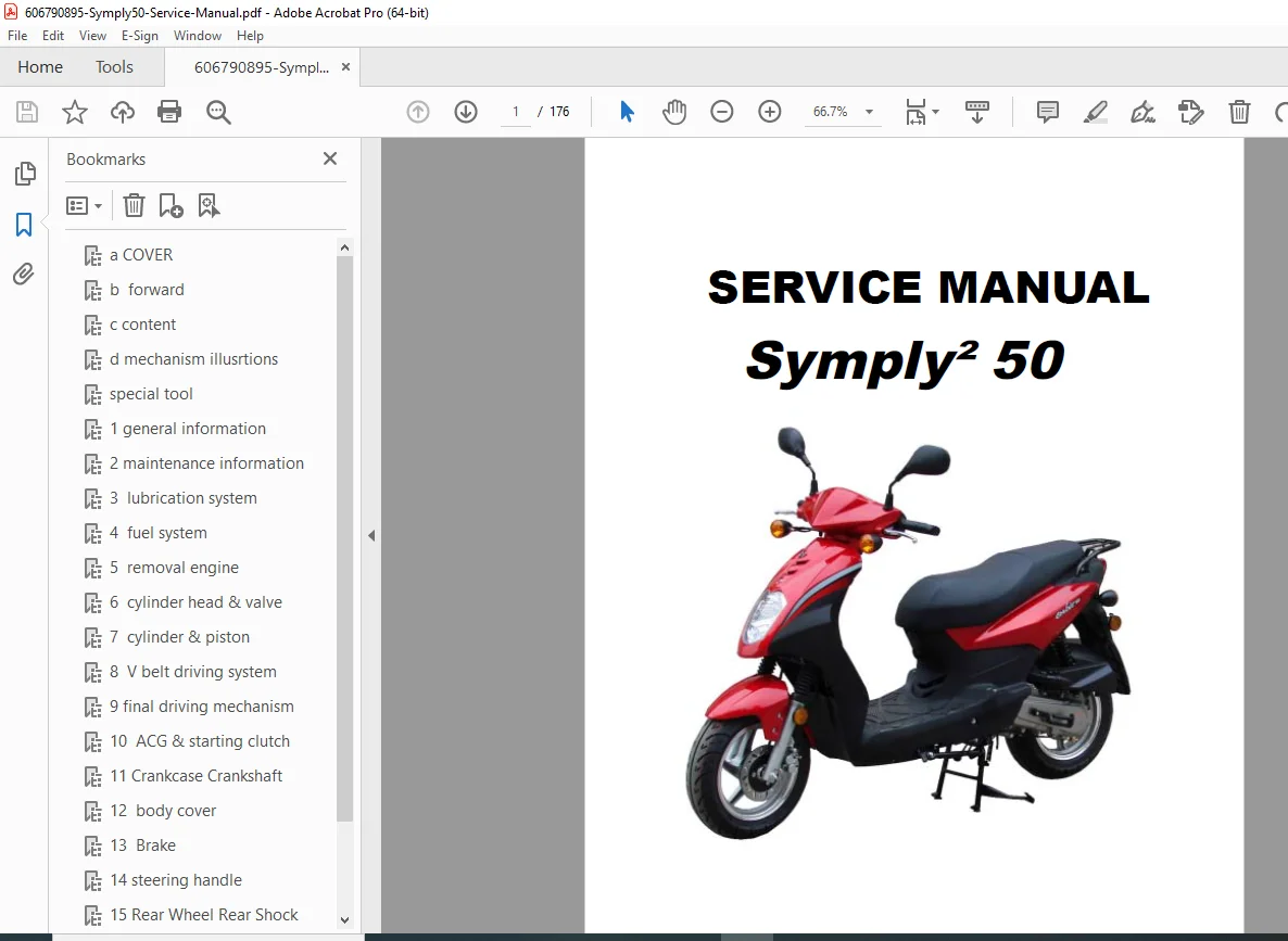
SYM Symply² 50 Service Manual PDF DOWNLOAD
Original price was: $95.00.$26.95Current price is: $26.95.
Complete factory service manual for the SYM Symply² 50 (Symply2 50) 4-stroke scooter with 49.5cc engine. This comprehensive 176-page technical manual covers engine overhaul, CVT transmission, fuel system, electrical system, brakes, suspension, troubleshooting, and maintenance procedures. Essential for motorcycle technicians, scooter mechanics, and DIY owners performing repairs on this SANYANG 50cc model with GY6-style engine and belt drive system.
Description
SYM Symply² 50 Service Manual SANYANG 50cc Scooter Repair Guide PDF DOWNLOAD
DESCRIPTION
SYM Symply² 50 Scooter Service Manual – Complete Workshop Documentation
This official SYM Symply 50 service manual provides comprehensive repair and maintenance procedures for the SYM (SANYANG) Symply² 50 scooter. Published by San Yang Industry Co., Ltd., this manual is the authoritative technical reference for motorcycle technicians servicing Symply2 scooter repair guide equipped vehicles with 4-stroke engines.
Model Overview – SYM Symply² 50
Model: Symply² 50 (also written as Symply2 50)
Engine: 49.5cc 4-stroke, forced air-cooled, single cylinder
Manufacturer: SANYANG (San Yang Industry Co., Ltd.)
Manual Pages: 176 pages
Manual Type: Complete Service Manual
Technical Specifications
Engine Specifications:
- Type: 4-stroke, forced air-cooled
- Displacement: 49.5cc
- Bore: 39.0mm
- Stroke: 41.5mm
- Compression Ratio: 11.8:1
- Max Power: 2.35 kW @ 8500 rpm
- Max Torque: 2.91 N·m @ 6500 rpm
- Cylinder: Single cylinder, horizontal arrangement
- Installation: Vertical, below center, incline 80°
- Ignition: C.D.I. (Capacitor Discharge Ignition)
- Starting System: Electric & kick starter
- Lubrication: Forced-circulation & splash system
- Air Filtration: Paper filter
- Fuel: Petrol (gasoline)
Transmission:
- Primary Reduction: Belt drive (CVT)
- Secondary Reduction: Gear
- Clutch: Centrifugal, dry type
- Transmission Type: C.V.T. (Continuously Variable Transmission)
Chassis and Dimensions:
- Overall Length: 1894mm
- Overall Width: 694mm
- Overall Height: 1138mm
- Wheelbase: 1327mm
- Dry Weight: 99kg (Front: 40kg, Rear: 59kg)
- Max Load: 209kg (Front: 84kg, Rear: 125kg)
- Passenger Capacity: Two persons / 150kg
Suspension:
- Front: Telescopic fork
- Rear: Single swing arm
Tires:
- Front: 120/70-12 (56J)
- Rear: 130/70-12 (56J)
Brakes:
- Front: Disc brake (Ø 190mm)
- Rear: Drum brake (Ø 110mm)
Performance:
- Max Speed: 45 km/h
- Climb Ability: 20° or below
- Speedometer Range: 0-80 km/h
Exhaust System:
- Muffler Type: Expansion & Pulse type
- Exhaust Position: Right side, backward
- Noise Emission: <70 dB
Electrical:
- Horn: 95-115 dB(A)
Complete Service Manual Contents
CHAPTER 1 – GENERAL INFORMATION/TROUBLE DIAGNOSIS
Symbols and Marks:
- Warning – Serious injury/death hazards
- Caution – Equipment damage prevention
- Engine oil – SAE 10W-30 API SH/CD class requirement
- Grease – King Mate G-3 recommended
- Locking sealant – Medium strength application
- Oil seal – Lubrication requirements
- Brake fluid – DOT3 or WELLRUN specification
- Special tools indication
- Correct/Wrong installation markers
- Component directions and assembly indicators
General Safety:
- Carbon monoxide – Ventilation requirements
- Gasoline handling – Fire and explosion hazards
- Battery safety:
- Explosive gas warnings
- Sulfuric acid handling
- Eye and skin protection
- Emergency procedures
- Used engine oil – Skin cancer prevention
- Brake shoe – Dust inhalation hazards
- Brake fluid – Paint damage prevention
Service Precautions:
- SANYANG genuine parts requirement
- Special tools usage (7 specialized tools listed)
- Metric tools requirement
- Component cleaning procedures
- Electrical connector handling:
- Terminal insertion techniques
- Boot covering requirements
- Pin inspection procedures
- Proper disconnection methods
- Wire harness routing
- Heat protection
- Sharp edge protection
- Handlebar clearance
- Twist prevention
- Connector rust cleaning
- Test instrument operation
Specifications:
- Complete technical data (detailed above)
- Dimensional specifications
- Weight distribution
Torque Values:
- Engine torque specifications
- Frame torque specifications
- Critical fastener torque settings
Trouble Diagnosis:
- Comprehensive troubleshooting charts
- Symptom-based diagnosis
- Electrical system troubleshooting
- Engine performance issues
Lubrication Points:
- Complete lubrication diagram
- Service interval specifications
- Recommended lubricants
CHAPTER 2 – MAINTENANCE INFORMATION
Maintenance Schedule:
- Periodic service intervals
- Component inspection checklists
- Replacement schedules
- Adjustment procedures
Special Tools:
- SYM-6204010 – Outer bearing puller
- SYM-3110A00 – ACG flywheel puller
- SYM-9020100 – Lock nut puller
- SYM-2210100 – Universal holder (MDF/clutch outer)
- SYM-2301000 – Clutch spring compressor
- SYM-9020200 – Clutch nut wrench
- SYM-2822100-GY6 – GY6 starter gear puller
CHAPTER 3 – LUBRICATION SYSTEM
Oil System:
- Engine oil circulation
- Oil pump operation
- Oil filter service
- Oil change procedures
- Oil capacity specifications
- Oil level checking
CHAPTER 4 – FUEL SYSTEM
Fuel Components:
- Fuel tank removal and installation
- Fuel unit service
- Carburetor service:
- Disassembly procedures
- Jet sizing
- Float level adjustment
- Mixture adjustment
- Air cleaner maintenance
- Fuel line routing
- Throttle cable adjustment
CHAPTER 5 – ENGINE REMOVAL
Complete Engine Removal:
- Pre-removal preparation
- Exhaust system disconnection
- Electrical disconnections
- CVT cover removal
- Engine mounting bolt removal
- Extraction procedures
- Installation procedures
CHAPTER 6 – CYLINDER HEAD/VALVE
Valve Train Service:
- Cylinder head removal
- Valve clearance adjustment
- Valve inspection
- Valve guide service
- Valve seat reconditioning
- Head gasket replacement
- Torque specifications
CHAPTER 7 – CYLINDER/PISTON
Cylinder Assembly:
- Cylinder removal
- Piston removal
- Piston ring service:
- Ring gap measurement
- Ring installation
- Piston pin service
- Cylinder bore measurement
- Honing procedures
CHAPTER 8 – “V” TYPE BELT DRIVING SYSTEM/KICK STARTER ARM/STARTER CLUTCH
CVT Transmission:
- V-belt drive system operation
- Drive pulley (variator) service:
- Roller weights
- Ramp plate
- Movable face
- Driven pulley (clutch) service:
- Clutch spring
- Clutch shoes
- Engagement RPM
- V-belt inspection and replacement
- Kick starter arm mechanism
- Starter clutch service
CHAPTER 9 – FINAL DRIVING MECHANISM
Final Drive:
- Reduction gear service
- Output shaft service
- Bearing replacement
- Oil seal service
- Gear backlash adjustment
CHAPTER 10 – A.C. GENERATOR/STARTING CLUTCH
Charging System:
- A.C. Generator (alternator) testing
- Stator coil inspection
- Rotor removal (flywheel puller required)
- Starting clutch service
- Voltage output testing
CHAPTER 11 – CRANKCASE/CRANKSHAFT
Crankshaft Assembly:
- Crankcase splitting
- Crankshaft inspection
- Big end bearing service
- Main bearing replacement
- Crankcase reassembly
- Sealant application
CHAPTER 12 – BODY COVER
Body Panel Service:
- Front cover removal
- Side panel removal
- Floor panel removal
- Seat removal
- Panel fastener locations
CHAPTER 13 – BRAKE SYSTEM
Brake Service:
- Front disc brake:
- Brake lever adjustment
- Brake pad inspection
- Caliper service
- Rotor measurement
- Brake fluid service
- Rear drum brake:
- Brake lever adjustment
- Brake shoe inspection
- Drum measurement
- Adjustment procedures
CHAPTER 14 – STEERING/FRONT WHEEL/FRONT SHOCK ABSORBER
Front End Service:
- Steering head bearing service
- Front fork (telescopic):
- Disassembly
- Oil change
- Spring inspection
- Seal replacement
- Front wheel service
- Bearing replacement
- Alignment procedures
CHAPTER 15 – REAR WHEEL/SUSPENSION
Rear Suspension:
- Rear wheel removal
- Single swing arm service
- Rear shock absorber service
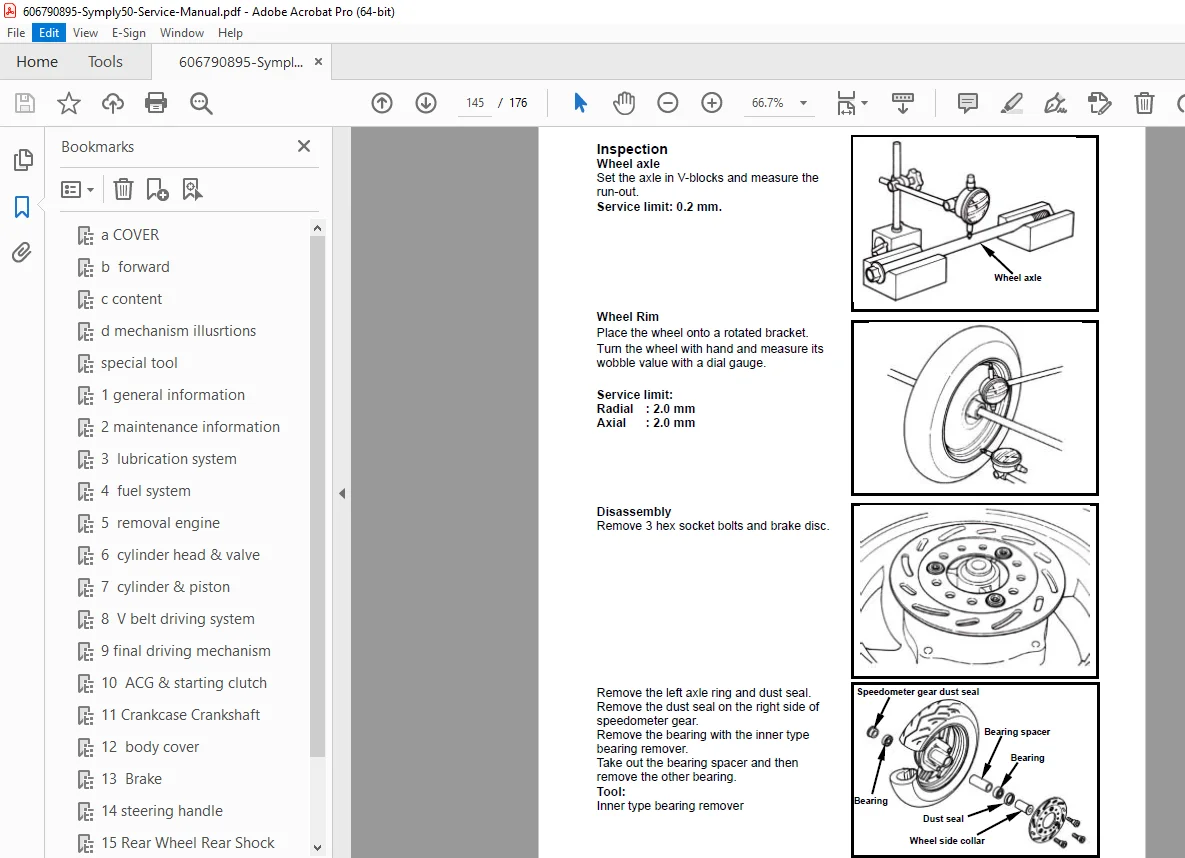
- Wheel bearing replacement
- Axle inspection
CHAPTER 16 – ELECTRICAL EQUIPMENT
Complete Electrical System:
- Battery service
- Fuse locations
- CDI unit (C.D.I.)
- Ignition coil testing
- REG.REC (Regulator/Rectifier)
- Head light and position light
- Tail light service
- Turn signal lights (front and rear)
- Horn testing
- Meter (instrument cluster)
- Switches:
- Ignition switch
- Light/starter switch
- Engine control switch
- High/low beam switch
- Seat open switch
- Turn signal switch
- Horn switch
- Winker relay
- Start magnetic switch
- Wiring harness routing
- Connector service
CHAPTER 17 – ELECTRICAL DIAGRAM
Wiring Schematics:
- Complete wiring diagram
- Color-coded wire identification
- Component locations
- Circuit descriptions
Component Locations (Mechanism Illustrations)
Left Side View:
- Meter (instrument cluster)
- Front turn signal light
- Head light/Position light
- Front disc brake
- Engine number location
- Light/starter switch
- Engine control switch
- Battery/Fuse/CDI location
- Engine oil draining bolt
- Winker relay
- Front brake lever
- Ignition switch
Right Side View:
- High & low beam/Seat open/Turn signal/Horn switches
- Rear brake lever
- Start magnetic switch
- Fuel tank/Fuel unit
- Horn/REG.REC
- Frame number location
- Tail light
- Rear turn signal light
- Air cleaner
- Gear oil filling bolt
- Gear oil draining bolt
- Exhaust muffler
- Ignition coil
- Oil level gauge
- A.C. Generator
Manufacturer Information
San Yang Industry Co., Ltd.
- Service Department
- SANYANG (SYM Brand)
Recommended Products:
- Engine Oil: SAE 10W-30 API SH/CD class
- Grease: King Mate G-3
- Brake Fluid: DOT3 or WELLRUN
Why This Manual is Essential
This 50cc scooter troubleshooting guide provides:
✓ Factory-authorized procedures – Official SANYANG documentation
✓ Complete system coverage – All mechanical and electrical systems
✓ CVT transmission service – V-belt drive detailed procedures
✓ 4-stroke engine overhaul – Complete disassembly/assembly
✓ Electrical system diagnosis – Full wiring diagrams
✓ GY6-style engine – Common 50cc platform service
✓ Special tools – 7 specialized tools illustrated
✓ Safety protocols – Comprehensive warnings and precautions
Perfect For
- Motorcycle mechanics specializing in scooter repair
- Scooter service shops maintaining SYM vehicles
- DIY scooter owners performing their own maintenance
- Technical training schools teaching small engine repair
- Motor scooter enthusiasts restoring Symply² scooters
- Parts departments identifying replacement components
- Fleet maintenance with SYM scooters
- GY6 engine specialists servicing 50cc scooters
Applications and Usage
SYM Symply² 50 scooters are popular for:
- Urban commuting and city transportation
- Campus and short-distance travel
- Economical personal transportation
- Entry-level motorcycling
- Asian and international markets
- Light delivery applications
Important Notes
- Specifications subject to change without notice
- Actual vehicle prevails if different from manual
- SANYANG genuine parts required for warranty
- Metric tools only – No English system
- Copyright protected – No unauthorized duplication
FILE DETAILS
| Specification | Details |
|---|---|
| Manual Name | SYM Symply² 50 Service Manual |
| Model | Symply² 50 (Symply2 50) |
| Engine | 49.5cc 4-stroke, single cylinder, air-cooled |
| Manufacturer | SANYANG (San Yang Industry Co., Ltd.) |
| Total Pages | 176 pages |
| File Format | |
| PDF Quality | Good Quality – Factory Service Manual |
| File Size | 4.7 MB |
| Language | English |
| Manual Type | Complete Workshop Service Manual |
| Page Size | A4 (595 x 842 pts) |
