
SZD-54-2 Perkoz Technical Service Manual PDF DOWNLOAD
Original price was: $95.00.$30.95Current price is: $30.95.
Download the official SZD-54-2 Perkoz service manual PDF for detailed maintenance, repairs, and assembly on this high-performance glider. This SZD-54-2 Perkoz glider maintenance guide covers adjustments, inspections, weighing, and composite repairs. Ideal for pilots and technicians needing an Allstar PZL sailplane repair manual PDF or SZD-54-2 technical service handbook download. High-quality 170-page PDF with diagrams, tolerances, and lubrication instructions.
Description
SZD-54-2 Perkoz Technical Service Manual PDF DOWNLOAD
Description
The SZD-54-2 Perkoz service manual PDF is a comprehensive technical resource for maintaining and repairing the Allstar PZL Glider SZD-54-2 “Perkoz,” a two-seat composite sailplane certified under CS-22 specifications. This guide details assembly/disassembly procedures, system descriptions, tolerances, lubrication, weighing, equipment lists, periodic inspections, and repair techniques for composite and non-composite parts, ensuring safe and efficient operation.
File Details:
- Manual Name: TECHNICAL SERVICE MANUAL for a sailplane SZD-54-2 “Perkoz”
- Models Covered: SZD-54-2 “Perkoz” (including variants with plane wingtips, winglets, or long wingtips)
- Year: 2014 (Issue II – April 2014, with revisions in 2015 and 2017)
- Manual PDF Quality: High-resolution, searchable text with diagrams, tables, and illustrations
- No. of Pages: 170
The manual is well-organized with a detailed table of contents for quick reference, extracted and categorized below using bullet points for main sections and sub-bullets for subsections. It also includes a table of figures for visual aids in repairs and inspections.
Table of Contents:
- SECTION 0. ISSUANCES
- 0.1. Record of revisions
- 0.2. List of effective pages
- 0.3. Table of contents
- 0.4. Table of figures
- SECTION 1. DESCRIPTION AND TECHNICAL DATA
- 1.1. Sailplane description
- 1.2. Sailplane technical data
- 1.3. Sailplane three view drawing
- 1.4. Crew mass balancing
- SECTION 2. ASSEMBLING AND DISASSEMBLING, SYSTEMS DESCRIPTION
- 2.1. Wings assembling and disassembling
- 2.1.1. Description of the wing-fuselage connection
- 2.1.2. Wings rigging
- 2.1.3. Wings de-rigging
- 2.2. Assembling and disassembling wingtips
- 2.2.1. Assembling wingtips: plane or winglet
- 2.2.2. Disassembling wingtips: plane or winglet
- 2.2.3. Assembling and disassembling long wingtips
- 2.3. Horizontal tailplane assembling and disassembling
- 2.4. Elevator mounting and dismounting
- 2.5. Rudder mounting and dismounting
- 2.6. Ailerons mounting and dismounting
- 2.6.1. Wing aileron dismounting
- 2.6.2. Long wingtip aileron dismounting
- 2.7. Nose wheel mounting and dismounting
- 2.8. Main wheel mounting and dismounting
- 2.9. Main landing gear mounting and dismounting
- 2.10. Tail wheel mounting and dismounting
- 2.11. Canopy
- 2.12. Rudder control system
- 2.13. Elevator, aileron and longitudinal trimming control system
- 2.14. Airbrake control system
- 2.15. Front instrument panel
- 2.15.1. Front instrument panel mounting and dismounting
- 2.15.2. SP3 stall warning device installation
- 2.16. Rear instrument panel
- 2.16.1. Rear instrument panel mounting and dismounting
- 2.17. Electric system
- 2.18. Removing rear seat pan
- 2.19. Tow releases control system
- 2.20. Battery and equipment mounting in luggage compartment
- 2.21. Sailplane drainage system
- 2.1. Wings assembling and disassembling
- SECTION 3. TECHNICAL SPECIFICATION, TOLERANCES AND ADJUSTMENT
- 3.1. Tire pressure
- 3.2. Cables tension
- 3.3. Fuselage control devices motion resistance forces
- 3.4. Allowable backlashes and tolerances in mounting connections and sailplane control systems
- 3.4.1. Allowable control stick play
- 3.4.2. Backlashes in the connections of torsional tubes with drivers in aileron and airbrake control systems
- 3.4.3. Maximum allowable backlashes on sailplane main unit connection fittings
- 3.4.4. Maximum allowable radial backlash in control surfaces hinges
- 3.4.5. Allowable play – airbrake plates shift
- 3.5. Adjustment of sailplane assemblies and control systems
- 3.5.1. General notes
- 3.5.2. Adjustment of aileron control system in wing
- 3.5.3. Adjustment of airbrake control system in wing
- 3.5.4. Adjustment of aileron control system in fuselage
- 3.5.5. Adjustment of elevator control system
- 3.5.6. Adjustment of cables tension in rudder control system
- 3.5.7. Adjustment of airbrake control system in fuselage
- 3.5.8. Adjustment of trimmer control system
- 3.5.9. Adjustment of wheel brake
- 3.5.10. Adjustment of rear seat pan
- SECTION 4. SPECIAL TOOLS SPECIFICATION
- 4.1. Tire pumping end
- 4.2. Wingtips mounting key
- 4.3. Rear fitting assembly key
- 4.4. Mounting wrench
- SECTION 5. LUBRICATION INSTRUCTION
- 5.1. General
- 5.1.1. Rolling and slide bearings lubrication
- 5.1.2. Mounting elements lubrication
- 5.1.3. Bowden cables lubrication
- 5.1.4. Elements not requiring lubrication
- 5.1. General
- SECTION 6. SAILPLANE ALIGNMENT AND CONTROL SURFACES DEFLECTION INSPECTION
- SECTION 7. SAILPLANE WEIGHING
- 7.1. Method of weighing
- 7.2. Sailplane without pilots mass and CG position
- 7.3. Calculation of sailplane without pilots CG position
- SECTION 8. EQUIPMENT
- 8.1. Minimum equipment
- 8.1.1. Airspeed indicators
- 8.1.2. Altimeters
- 8.1.3. Accelerometers
- 8.1.4. Stall warning unit
- 8.1.5. Safety harnesses
- 8.1.6. Batteries
- 8.1.7. Tow releases
- 8.2. Additional equipment
- 8.2.1. Variometers and related accessories
- 8.2.2. Artificial horizon
- 8.2.3. Compasses
- 8.2.4. Turn and bank indicators
- 8.2.5. Bank indicators and inverted flight bank indicators
- 8.2.6. Stall warning device
- 8.2.7. Batteries
- 8.2.8. Transceiver
- 8.2.9. Emergency Locator Transmitter
- 8.2.10. Transponders
- 8.3. Other additional equipment
- 8.1. Minimum equipment
- SECTION 9. INSPECTION OF CONTROL SURFACES BALANCE
- SECTION 10. AIRWORTHINESS LIMITATIONS
- 10.1. Sailplane service life
- 10.2. Service life of elements installed on sailplane
- 10.2.1. Crew safety harness
- 10.2.2. Tow releases
- 10.2.3. Board instruments
- SECTION 11. LIST OF MAINTENANCE DOCUMENTS OF ASSEMBLIES APPROVED REGARDLESS OF SAILPLANE
- SECTION 12. CLEANING AND MAINTENANCE
- 12.1. Canopy perspex
- 12.2. Painted exterior surfaces
- SECTION 13. SAILPLANE TRANSPORT AND STORAGE IN A HANGAR
- 13.1. Sailplane transport at the airfield
- 13.2. Storage in a hangar
- 13.2.1. Sailplane lifting and moving
- 13.2.2. Sailplane hanging
- SECTION 14. DISMOUNTED SAILPLANE TRANSPORT
- 14.1. Transport in sailplane trailer
- 14.2. Transport in container
- SECTION 15. INFORMATION TABLES
- 15.1. Pictograms
- 15.2. Terms of use tables
- 15.2.1. Limitation table “Maximum allowed airspeed”
- 15.2.2. Limitation table “Allowed VNE values for various flight altitudes”
- 15.2.3. Tables “Pressure in tires”
- 15.2.4. Table “Manoeuvring loads and loading”
- 15.2.5. Table “Individual loading plan”
- 15.2.6. Table “Approved manoeuvres”
- 15.2.7. Table “Pre-flight checklist”
- 15.2.8. Compass deviation table
- SECTION 16. PERIODIC MAINTENANCE
- 16.1. General rules for periodic maintenance
- 16.2. Periodic maintenance of SP3 stall warning device
- 16.3. Periodic maintenance of board instruments
- 16.4. Periodic maintenance of radio and electronic equipment
- 16.5. Periodic maintenance of tow releases
- 16.6. Periodic maintenance of wheels
- 16.7. Rules for operations of cables
- 16.8. Inspection of non-accessible areas in control systems
- 16.9. Inspection of main units subjected to fatigue loads
- 16.10. Maintenance work and actions carried out on a sailplane
- 16.10.1. Complete structure inspection on rigged sailplane
- 16.10.2. Inspection of instruments and pneumatic installation
- 16.10.3. Check operation of electric turn indicator (if installed)
- 16.10.4. Check electric connection between CG tow release and control sticks in a cockpit
- 16.10.5. Check operation and correct fitting of additional installations
- 16.10.6. Verify reliable de-rigging and rigging of sailplane main units
- 16.10.7. Complete structure inspection on de-rigged sailplane
- 16.10.8. Verify mass balance of control surfaces
- 16.10.9. Complete sailplane weighing
- 16.10.10. Perform test flight
- 16.10.11. Check the patency of all drainage holes
- SECTION 17. SAILPLANE REPAIRS
- 17.1. Introductory remarks
- 17.2. Composite structures repairing
- 17.2.1. Repair conditions
- 17.2.2. Damages classification
- 17.3. Typical composite structures repairs
- 17.3.1. Sandwich shell laminate-foam-laminate
- 17.3.2. Solid laminate shell
- 17.3.3. Debonding
- 17.3.4. Fuselage central section skin repair – zone II
- 17.3.5. Repair of rear (sandwich) fuselage part – zone III
- 17.3.6. Inner structure debonding
- 17.4. Painting
- 17.5. Materials for typical repairs of composite structures
- 17.6. Non-composite parts repair
- 17.6.1. Metal parts repair
- 17.6.2. Rudder control system cables replacement
- 17.6.3. Reaming of main bolt sleeves and rear fittings
- 17.6.4. Canopy perspex
- 17.6.5. Parts replacement
- 17.7. Primary and secondary structure
- 17.7.1. Primary structure
- 17.7.2. Secondary structure
- 17.8. Assemblies interchangeability
- SECTION 18. ANNEXES
- 18.1. Equipment list
- 18.2. Record of sailplane weighing and determining of CG
- 18.3. Elevator, rudder and ailerons balance records
- 18.4. Calculation record of sailplane without pilots CG
- 18.5. Record of control surfaces movements
- 18.6. Glider alignment record
- 18.7. Measurement record for glider control systems friction and activation forces
- SECTION 19. SUPPLEMENTS
- 19.1. Introduction
- 19.2. List of inserted supplements
- 19.3. Supplements – List of actual pages
Table of Figures (Extracted and Categorized):
- General Views: Fig. 1-1. Sailplane 3-view drawing
- Assembly/Disassembly: Fig. 2-1. Wings rigging, Fig. 2-2. Assembling wingtip: plane or winglet, Fig. 2-3. Long wingtips assembling, Fig. 2-4. Detail A of wing – long wingtip connection, Fig. 2-5. Detail B of wing – long wingtip connection, Fig. 2-6. Horizontal tailplane assembling, Fig. 2-7. Nose wheel mounting, Fig. 2-8. Main landing gear, Fig. 2-9. Main landing wheel hub, Fig. 2-10. Canopy
- Control Systems: Fig. 2-11. Rudder control system, Fig. 2-12. Elevator, aileron and trimmer control system in fuselage, Fig. 2-13. Aileron control system in wings, Fig. 2-14. Airbrake control system in fuselage, Fig. 2-15. Airbrake control system in wing, Fig. 2-19. Scheme of electric installation, Fig. 2-21. Tow releases control system
- Instrument Panels: Fig. 2-16. Front instrument panel installation diagram, Fig. 2-17. SP3 stall warning device installation, Fig. 2-18. Rear instrument panel installation diagram
- Other: Fig. 2-20. Rear seat pan mounting, Fig. 2-22. Battery mounting in sailplane luggage compartment, Fig. 2-23. Sailplane drainage holes layout scheme, Fig. 3-1. Driver connection scheme, Fig. 4-1. Tire pumping end, Fig. 4-2. Wingtips mounting key, Fig. 4-3. Rear fitting assembly key, Fig. 5-1. Lubrication scheme, Fig. 6-1. Sailplane alignment and control surfaces deflection, Fig. 7-1. Sailplane weighing, Fig. 7-2. CG range limits for a sailplane without pilots, Fig. 7-3. Location of balancing weight in sailplane tail, Fig. 7-4. Battery mounting in sailplane tail, Fig. 9-1. Inspection of control surfaces balance, Fig. 13-1. Sailplane lifting and moving, Fig. 13-2. Sailplane hanging areas
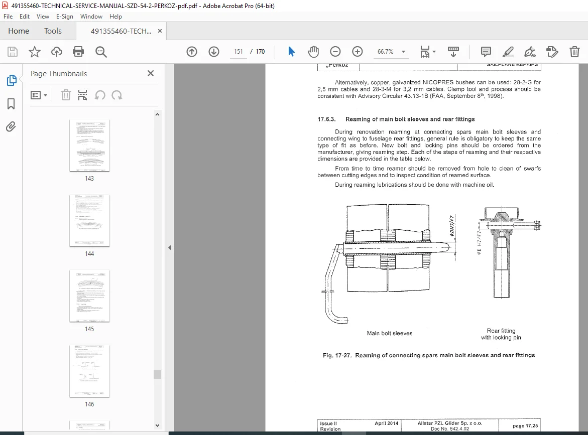
- Repairs: Fig. 17-1. Zoning and material specification for fuselage repairs, Fig. 17-2. Zoning and material specification for wing repairs, Fig. 17-3. Material specification for vertical stabilizer repairs, Fig. 17-4. Material specification for rudder repairs, Fig. 17-5. Material specification for horizontal stabilizer repairs, Fig. 17-6. Material specification for elevator repairs, Fig. 17-7. Damage to the sandwich shell, Fig. 17-8. Repair of damaged sandwich outer layer, Fig. 17-9. Damage to sandwich outer layer and foam, Fig. 17-10. Repair of damaged sandwich outer layer and foam, Fig. 17-11. Through damage, Fig. 17-12. Repair of through damage, Fig. 17-13. Solid laminate shell damage, Fig. 17-14. Repair of solid laminate shell, Fig. 17-15. Wet repair, Fig. 17-16. Dry repair, Fig. 17-17. Damage to sandwich outer shell, Fig. 17-18. Repair of damage to sandwich outer shell, Fig. 17-19. Damage to sandwich outer shell and foam, Fig. 17-20. Repair of damage to sandwich outer shell and foam, Fig. 17-21. Sandwich structure trough damage, Fig. 17-22. Repair of sandwich structure trough damage, Fig. 17-23. Damage to sandwich outer shell, detail “A”, Fig. 17-24. Repair of damage to sandwich outer shell, detail “A”, Fig. 17-25. Inner structure debonding, Fig. 17-26. Repair of inner structure debonding, Fig. 17-27. Reaming of connecting spars main bolt sleeves and rear fittings, Fig. 17-28. Way to avoid further cracking of perspex
This Allstar PZL sailplane repair manual PDF is your essential Perkoz glider assembly and disassembly PDF companion for keeping the SZD-54-2 in peak condition.
Elevate your glider maintenance today—download this SZD-54-2 Perkoz glider maintenance guide instantly and ensure airworthy performance with expert guidance at your fingertips!