Tadano AW-250TG-3 Aerial Platform (Circuit Diagrams & Data) Service Manual SN 420454 – PDF DOWNLOAD
$21.95
Tadano AW-250TG-3 Aerial Platform (Circuit Diagrams & Data) Service Manual SN 420454 – PDF DOWNLOAD
Description
Tadano AW-250TG-3 Aerial Platform (Circuit Diagrams & Data) Service Manual SN 420454 – PDF DOWNLOAD
FILE DETAILS:
Tadano AW-250TG-3 Aerial Platform (Circuit Diagrams & Data) Service Manual SN 420454 – PDF DOWNLOAD
Language : English
Pages : 93
Downloadable : Yes
File Type : PDF
DESCRIPTION:
Tadano AW-250TG-3 Aerial Platform (Circuit Diagrams & Data) Service Manual SN 420454 – PDF DOWNLOAD
Foreword:
This Service Manual (Circuit Diagrams and Data) describes the hydraulic circuits and electrical circuits applicable to the AW-250TG-3 (AMC3 specification) model aerial platform.
- For the actual works, perform appropriate repair and service with referring to the separate repair manual, operation and maintenance manual, and parts catalog of the applicable model.
- This manual applies to the aerial platform with the specification numbers below. Be sure to check the specification number on the nameplate of your aerial platform before operation.
- When part replacement is needed, refer to the parts catalog first to check the disassembly unit as well as the parts sales unit.
TABLE OF CONTENTS:
Tadano AW-250TG-3 Aerial Platform (Circuit Diagrams & Data) Service Manual SN 420454 – PDF DOWNLOAD
AW-250TG-3_C2-1E 1
Foreword 2
1 Applicable spec No 2
2 Outline of specifications 3
3 Group index 4
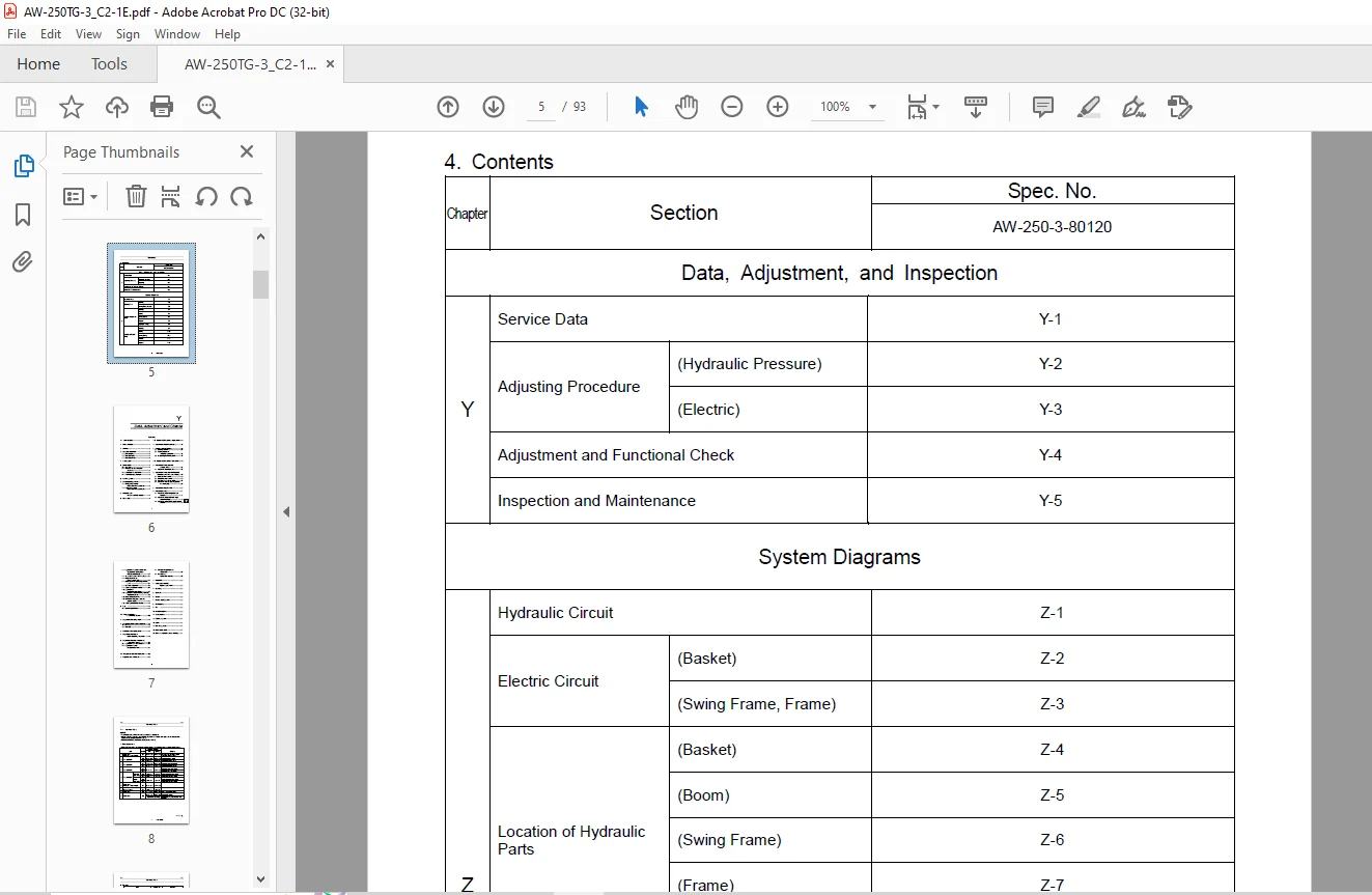
4 Contents 5
(Y)Data, Adjustment and Checks 6
Y-1 Service Data 8
1 Preset pressure 8
2 Oil level 9
3 Hydraulic equipment 9
3 1 Hydraulic pump 9
3 2 Hydraulic motor 9
3 3 Hydraulic cylinder 9
4 Swing section 9
5 Boom section 10
5 1 Slide plate 10
5 2 Clearance between slide plate and boom 10
5 3 Boom bend and deformation 11
5 4 Boom telescoping wire rope 12
6 Leveling system 12
7 Other regulating devices 13
7 1 Elevation angle control (AMC automatic stop position) 13
7 2 Boom length control (AMC automatic stop position) 14
8 Integration test (no-load operation speed) 15
9 Mass table 16
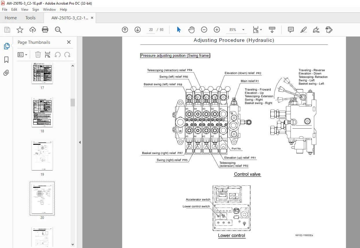
Y-2 Adjusting Procedure (Hydraulic) 17
1 Adjustment of relieving pressure 17
2 Leveling cylinder bleeding 22
2 1 Bleeding operation 23
2 2 Leveling adjustment after bleeding operation 24
2 3 Pressurizing the leveling circuit 24
Y-3 Adjusting Procedure (Electric) 25
1 Adjustment of axle extension detector switch 25
1 1 Adjustment of detector switch 25
2 Adjustment of axle extension/retraction control detector switch (reed switch) 26
2 1 Removal of reed switch 27
2 2 Installation of reed switch 27
2 3 Operation check of reed switch 28
2 4 Adjustment of switch operating position (a-contact type) 29
3 Adjustment of touch switch 30
4 Adjustment of AMC 31
4 1 Adjustment of boom length detector zero/span 31
4 2 Adjustment of boom elevation angle detector zero/span 32
4 3 Adjustment of boom swing angle detector zero/span 33
4 4 Adjustment of moment zero/span and adjustment of working radius (measurement radius) 34
4 5 10° and 50° moment write-in method 38
4 6 Offset adjustment for boom operation valve 39
4 7 Offset adjustment for traveling operation valve 41
4 8 Valve span adjustment 42
4 9 Selecting acceleration method 43
4 10 Adjustment of accelerator (engine) span 44
4 11 Adjustment of machine (carrier) inclination angle detector zero 46
4 12 Fuzzy control adjustment 47
4 13 Initialization of adjusted values and selected values 48
4 14 Selecting of special specification 49
5 Data 50
5 1 Detector specifications 50
Y-4 Adjustment and Functional Check 52
1 Adjustment of steering wheel 52
2 Adjustment of slide plate clearances 53
2 1 Front axle 53
2 2 Rear axle 54
3 Installation of hydraulic pump 55
4 Adjustment of tension in boom telescoping wire rope 56
5 Adjustment of tension in hoses and cables inside boom 57
5 1 Adjustment of hose inside boom 57
5 2 Adjustment of tension in cable inside boom 58
Y-5 Inspection and Maintenance 59
1 Inspection and maintenance 59
1 1 Cautions of inspections and maintenance 59
1 2 Inspection and maintenance intervals 59
2 Inspection 60
3 Safety parts requiring regular replacement 60
4 Greasing 60
5 Gear oil 60
6 Engine 60
7 Engine cooling system 60
8 Fuel system 60
9 Tire 60
10 Hydraulic system 60
11 Swing system 61
12 Electrical system 61
13 Boom 61
14 Oils and greases 61
15 Consumable parts 61
16 Others (compulsion release method) 61
(Z)System Diagrams 62
Z-1 Hydraulic Circuit 64
Z-2 Electric Circuit (Basket) 65
Z-3 Electric Circuit (Swing Frame, Frame) 66
Z-4 Location of Hydraulic Parts (Basket) 67
1 Motor type 67
2 Cylinder type 68
Z-5 Location of Hydraulic Parts (Boom) 69
Z-6 Location of Hydraulic Parts (Swing Frame) 70
1 Swivel 70
2 Swing 71
3 Derrick 72
4 Telescoping/leveling 73
5 Return 74
Z-7 Location of Hydraulic Parts (Frame) 75
1 Frame 75
2 Control Assy 76
Z-8 Location of Hydraulic Parts (Hydraulic Pump) 77
1 Power train 77
2 Pump piping 78
3 Solenoid valve 79
4 Suction 80
Z-9 Location of Electric Parts (Basket) 81
1 Basket wiring 81
2 Panel 82
3 Foot switch 83
4 Touch switch 84
Z-10 Location of Electric Parts (Boom) 85
Z-11 Location of Electric Parts (Swing Frame) 86
1 Swing frame wiring 86
2 Relay box 87
Z-12 Location of Electric Parts (Frame) 88
Z-13 Location of Electric Parts (Option) 89
1 Vertical/horizontal movement selector switch 89
2 Horizontal operation switch and vertical operation switch 90
3 Rotary beacon 91
4 Headlamp 92
History of revision 93
IMAGES PREVIEW OF THE MANUAL:
Questions? Email us: [email protected]
https://vimeo.com/839707536?share=copy
PLEASE NOTE:
- This is not a physical manual but a digital manual – meaning no physical copy will be couriered to you. The manual can be yours in the next 2 mins as once you make the payment, you will be directed to the download page IMMEDIATELY.
- This is the same manual used by the dealers inorder to diagnose your vehicle of its faults.
- Require some other service manual or have any queries: please WRITE to us at [email protected]
S.V