Tadano Faun All Terrain Crane AR-1000M-1 Circuit Diagram Manual SN GA5002 – PDF DOWNLOAD
$14.95
Tadano Faun All Terrain Crane AR-1000M-1 Circuit Diagram Manual SN GA5002 – PDF DOWNLOAD
Description
Tadano Faun All Terrain Crane AR-1000M-1 Circuit Diagram Manual SN GA5002 – PDF DOWNLOAD
FILE DETAILS:
Tadano Faun All Terrain Crane AR-1000M-1 Circuit Diagram Manual SN GA5002 – PDF DOWNLOAD
Language : English
Pages : 50
Downloadable : Yes
File Type : PDF
DESCRIPTION:
Tadano Faun All Terrain Crane AR-1000M-1 Circuit Diagram Manual SN GA5002 – PDF DOWNLOAD
Foreword:
- This manual contains all the hydraulic and electric circuit diagrams for the Model AR-1000M-1 all terrain crane.
- This manual is applicable to the machine of the Spec. Nos. given below. Before using this manual, check the
Spec. No. of your unit in the nameplate on the machine. - For proper repair and maintenance operations, use this manual together with the appropriate service manual,
operation and maintenance manual and the related parts catalog furnished separately.
TABLE OF CONTENTS:
Tadano Faun All Terrain Crane AR-1000M-1 Circuit Diagram Manual SN GA5002 – PDF DOWNLOAD
AR-1000M-1_C2-1E 1
Foreword 2
1 Applicable spec NO 2
2 Contents 3
(Y) Data, Adjustment and Checks 4
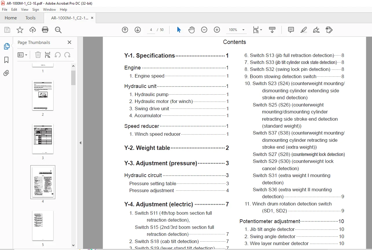
Y-1 Specifications 6
Engine 6
1 Engine speed 6
Hydraulic unit 6
1 Hydraulic pump 6
2 Hydraulic motor (for winch) 6
3 Swing drive unit 6
4 Accumulator 6
Speed reducer 6
1 Winch speed reducer 6
Y-2 Weight table 7
Y-3 Adjustment (pressure) 8
Hydraulic circuit 8
Pressure setting table 8
Pressure adjustment 9
Y-4 Adjustment (electric) 12
Switch adjustment 12
1 Switch S11 (4th/top boom section full retraction detection), switch S15 (2nd/3rd boom section full retraction detection) 12
2 Switch S18 (cab tilt detection) 12
3 Switch S19 (lever stand tilt detection) 12
Switch adjustment 12
4 Switch S20 (main winch dead wrap detection), switch S21 (auxiliary winch dead wrap detection) 12
5 Switch S12 (jib tilting operation detection) 13
6 Switch S13 (jib full retraction detection) 13
7 Switch S33 (jib tilt cylinder cock state detection) 13
8 Switch S32 (swing lock pin detection) 13
9 Boom stowing detection switch 13
10 Switch S23 (S24) (counterweight mounting/dismounting cylinder extending side stroke end detection) Switch S25 (S26) (counterweight mounting/dismounting cylinder retracting side stroke end detection (standard weight)) Switch S37 (S38) (counterweight mounting/dismounting cylinder retracting side stroke end (extra weight)) Switch S27 (S28) (counterweight lock detection) Switch S29 (S30) (counterweight lock cancel detection) Switch S31 (extra weight I mounting detection) Switch S36 (extra weight II mounting detection) 14
11 Winch drum rotation detection switch (SD1, SD2) 14
Potentiometer adjustment 15
1 Jib tilt angle detector 15
2 Swing angle detector 15
3 Wire layer number detector 15
Y-5 Adjustment and checks 16
Hydraulic pressure generating system 16
1 Air bleeding procedure of pump 16
2 Procedure of checking N2 gas filling pressure in accumulator 17
Swing system 17
1 Swing pilot circuit bleeding procedure 17
2 Swing brake circuit bleeding procedure 17
Winch system 17
1 Winch brake circuit air bleeding procedure 17
2 Adjustment of disorderly winding prevention roller 18
Telescoping system 18
1 Power-tilt jib circuit bleeding procedure 18
2 Power-extension jib circuit bleeding procedure 18
Crane operation 19
1 Operation pilot circuit air bleeding procedure 19
2 Engine speed adjustment 20
(Z) System Diagrams 21
Z-1_Hydraulic Circuit (Upper) 22
Z-2_Hydraulic Circuit (Lower) 0
Z-3_Electric Circuit (Upper) 26
Z-4_Electric Circuit (Crane electrical equipment) 31
Z-5_Electric Circuit (Electric circuit for mounting/dismounting) 32
Z-6_Electric Circuit (Engine electric circuit) 35
Z-7_Electric Circuit (Lower) 36
Z-8_Electric Circuit (Air conditioner) 38
Z-9_Electric Circuit (Upper wiring 1 (cab)) 40
Z-10_Electric Circuit (Upper wiring 2 (swing table)) 46
Z-11_Electric Circuit (Engine wiring) 48
Z-12_Electric Circuit (Lower wiring) 0
IMAGES PREVIEW OF THE MANUAL:
PLEASE NOTE:
- This is not a physical manual but a digital manual – meaning no physical copy will be couriered to you. The manual can be yours in the next 2 mins as once you make the payment, you will be directed to the download page IMMEDIATELY.
- This is the same manual used by the dealers inorder to diagnose your vehicle of its faults.
- Require some other service manual or have any queries: please WRITE to us at [email protected]
S.V