Description
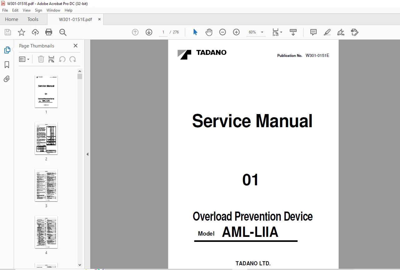
Tadano Faun AML-LIIA Overload Prevention Device Service Manual W301-0151E – PDF DOWNLOAD
FILE DETAILS:
Tadano Faun AML-LIIA Overload Prevention Device Service Manual W301-0151E – PDF DOWNLOAD
Language : English
Pages : 276
Downloadable : Yes
File Type : PDF
DESCRIPTION:
Tadano Faun AML-LIIA Overload Prevention Device Service Manual W301-0151E – PDF DOWNLOAD
Foreword:
This service manual (this document) is compiled to provide information on the AML-LIIA (overload prevention device) that is mounted on the Rough Terrain Crane GR-300N-1, TR-250M-7, GR-250N-1, GR-350N-1, and GR-160N-1, Tower reach Rough Terrain Crane GR-120F-1, and All Terrain Crane GA-700N-1.
- “Diagram of the AML-LIIA System” (Page 9, 36, 50, and 64) and “Input/Output Signals of the AML-LIIA System” (Page 10 to 35, 37 to 49, 51 to 63, and 65 to 86) in this document offers the general description on the electrical circuit of cranes GR-300N-1, TR-250M-7, GR-250N-1, GR-350N-1, GR-160N-1, GR-120F-1, and GA-700N-1. For the detailed electrical circuit, refer to the service manual (electrical circuit diagrams) of each model.
- For the actual works, perform appropriate repair and service with referring to the separate operation and maintenance manual, parts catalog, and service manual for each model.
- When part replacement is needed, refer to the parts catalog first to check the disassembly unit as well as the parts sales unit.
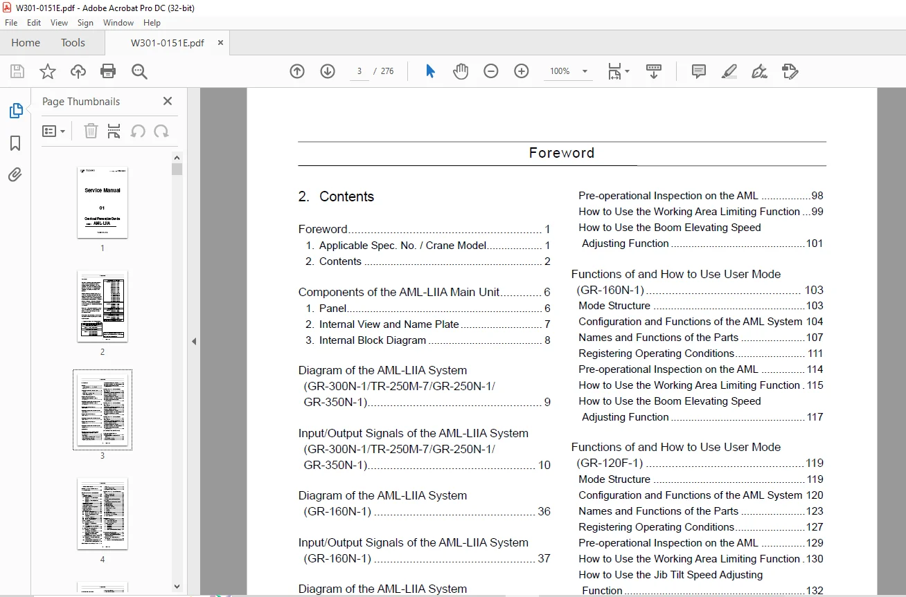
TABLE OF CONTENTS:
Tadano Faun AML-LIIA Overload Prevention Device Service Manual W301-0151E – PDF DOWNLOAD
W301-0151E 1
Forword 2
1 Applicable Spec No /Crane Model 2
2 Contents 3
Components of the AML-LIIA Main Unit 7
1 Panel 7
2 Internal View and Name Plate 8
3 Internal Block Diagram 9
Diagram of the AML-LIIA System (GR-300N-1/TR-250M-7/GR-250N-1/GR-350N-1) 10
Input/Output Signals of the AML-LIIA System (GR-300N-1/TR-250M-7/GR-250N-1/GR-350N-1) 11
Diagram of the AML-LIIA System (GR-160N-1) 37
Input/Output Signals of the AML-LIIA System (GR-160N-1) 38
Diagram of the AML-LIIA System (GR-120F-1) 51
Input/Output Signals of the AML-LIIA System (GR-120F-1) 52
Diagram of the AML-LIIA System (GA-700N-1) 65
Input/Output Signals of the AML-LIIA System (GA-700N-1) 66
[OPERATION] 88
Functions of and How to Use User Mode (GR-300N-1/TR-250M-7/GR-250N-1/GR-350N-1) 88
Mode Structure 88
Configuration and Functions of the AML System 89
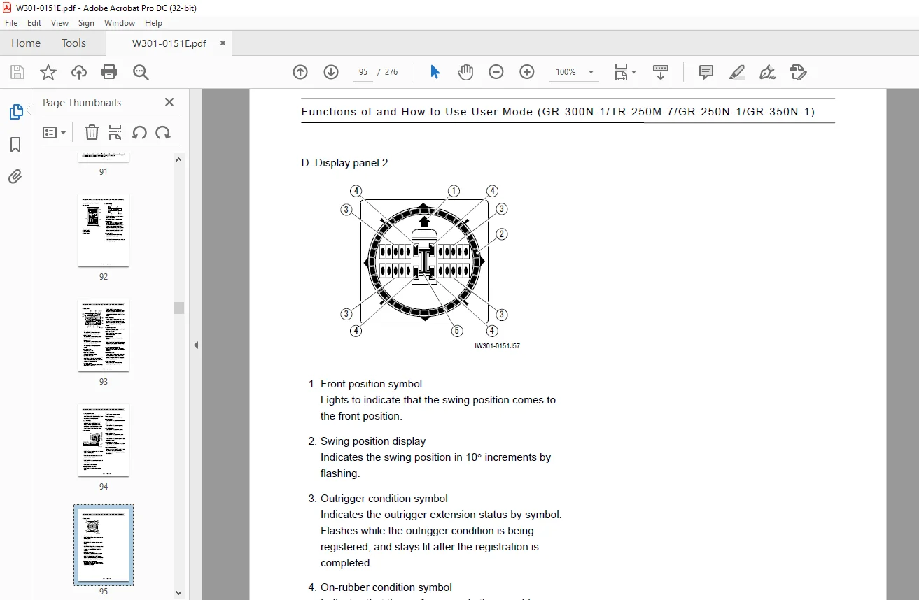
Names and Functions of the Parts 92
Registering Operating Conditions 96
Pre-operational Inspection on the AML 99
How to Use the Working Area Limiting Function 100
How to Use the Boom Elevating Speed Adjusting Function 102
Functions of and How to Use User Mode (GR-160N-1) 104
Mode Structure 104
Configuration and Functions of the AML System 105
Names and Functions of the Parts 108
Registering Operating Conditions 112
Pre-operational Inspection on the AML 115
How to Use the Working Area Limiting Function 116
How to Use the Boom Elevating Speed Adjusting Function 118
Functions of and How to Use User Mode (GR-120F-1) 120
Mode Structure 120
Configuration and Functions of the AML System 121
Names and Functions of the Parts 124
Registering Operating Conditions 128
Pre-operational Inspection on the AML 130
How to Use the Working Area Limiting Function 131
How to Use the Jib Tilt Speed Adjusting Function 133
Functions of and How to Use User Mode (GA-700N-1) 135
Mode Structure 135
Configuration and Functions of the AML System 136
Names and Functions of the Parts 139
Registering Operating Conditions 143
Pre-operational Inspection on the AML 146
How to Use the Working Area Limiting Function 147
How to Use the Boom Elevating Speed Adjusting Function 151
[ADJUSTMENT AND MAINTENANCE] 153
Outline of Adjustment Mode and Maintenance Mode 153
1 Keys and Switches for Adjustment and Maintenance 153
2 Mode Structure and Menu 154
3 Method of Shifting Modes 155
4 Method of Menu Selection 156
Required Adjustment After AML System Parts Replacement 157
Functions of and How to Use Adjustment Mode 158
Adjustment Procedures 158
1 Adjustment Initialization 159
1 1 Procedure of “Conversion Factors Resetting” 159
1 2 Procedure of “Moment Adjustment Resetting” 159
2 Boom Length Adjustment 160
3 Boom Angle Adjustment 161
4 Swing Angle Adjustment 162
5 Outrigger Extension Width Adjustment 163
6 Jib Angle Adjustment 164
7 Jib Length Adjustment 165
8 Moment Adjustment 166
8 1 Moment Zero-point Adjustment 167
8 2 Moment Span Preliminary Adjustment 167
8 3 Moment Zero-point Check and Fine Adjustment 168
8 4 Load Radius Adjustment 169
8 5 Moment Span Fine Adjustment 170
8 6 Moment Zero-point Recheck 171
9 Clock Adjustment 172
10 Swing Output Adjustment 173
10 1 Procedure of “AO Offset Value Resetting” 173
10 2 Swing output adjustment (AO offset adjustment) 173
11 Boom Elevating Output Adjustment 175
11 1Procedure of “Boom Elevating Characteristic Value Resetting” 175
11 2 Boom Elevating Output Adjustment (Boom Elevating Characteristic Adjustment) 175
12 Telescoping/retraction Output Adjustment 177
12 1 Procedure of “Retraction Characteristic Value Resetting” 177
12 2 Telescoping/retraction Output Adjustment (Retraction Characteristic Adjustment) 177
Other Functions and How to Use Them 179
1 Language 179
2 Overload History Display 179
3 Erasing the Overload History 180
Functions of and How to Use Maintenance Mode 181
1 Program Version Display 181
2 Data ID Number Display 181
3 Di Check 182
4 Ai Check 182
5 Elevating Cylinder Oil Pressure Monitor 183
6 Do Check 183
7 MDT (Multiplex Data Transmitter) Monitor 184
8 Key Switch Check 186
9 Display Unit Check 186
10 Error Data Display 186
11 Erasing the Error Data 187
12 Option (OP) Board Check 187
13 Ao Check 187
14 Sio Check 188
15 Adjust Monitor 188
16 Overload History Display 188
17 Erasing the Overload History 188
18 Clock adjustment 188
Error Message 189
1 Display of Error Message 189
2 How to Read the Error Message 189
3 How to Read the Error History 189
4 Troubleshooting Table 190
4 1 Group Code 0 190
4 2 Group Code 1 209
4 3 Group Code 2 211
4 4 Group Code 3 214
4 5 For GR-120F-1 Only (Group Code 0) 215
Disassembly of AML Main Unit 220
1 Removing Front Panel/Display Board 220
2 Removing Rear Panel/Connector Board/Current Output Board 220
3 Removing CPU Board/Analog Board /Power Board 221
3 1 Notes on ROM/EEPROM Replacement 221
[INFORMATION AND DATA] 222
Adjustment Value Table 222
Specification No : GR-300N-1-00101 222
Specification No : GR-300N-1-00102 222
Specification No : TR-250M-7-00101 223
Specification No : GR-250N-1-00101, -00201 223
Specification No : GR-250N-1-00105, -00205 223
1 Setting before adjustment 223
2 Detector adjustment 223
3 Slow stop adjustment 225
4 Setting after adjustment 225
Specification No : TR-250M-7-00102 226
Specification No : GR-250N-1-00102, -00202 226
Specification No : GR-250N-1-00106, -00206 226
1 Setting before adjustment 226
2 Detector adjustment 226
3 Slow stop adjustment 228
4 Setting after adjustment 228
Specification No : TR-250M-7-00103 229
Specification No : TR-250M-7-00104 229
Specification No : GR-250N-1-00103, -00203 229
Specification No : GR-250N-1-00104, -00204 229
Specification No : GR-250N-1-00107, -00207 229
Specification No : GR-250N-1-00108, -00208 229
1 Setting before adjustment 229
2 Detector adjustment 229
3 Slow stop adjustment 231
4 Setting after adjustment 231
Specification No : GR-350N-1-00101 232
Specification No : GR-350N-1-00102 232
1 Setting before adjustment 232
2 Detector adjustment 232
3 Slow stop adjustment 234
4 Setting after adjustment 234
Specification No : GR-350N-1-00103 235
Specification No : GR-350N-1-00104 235
1 Setting before adjustment 235
2 Detector adjustment 235
3 Slow stop adjustment 236
4 Setting after adjustment 236
Specification No : GR-160N-1-00101 237
Specification No : GR-160N-1-00102 237
1 Setting before adjustment 237
2 Detector adjustment 237
3 Slow stop adjustment 238
4 Setting after adjustment 238
Specification No : GR-120F-1-00101 239
1 Setting before adjustment 239
2 Detector adjustment 239
3 Slow stop adjustment 241
4 Speed adjustment 241
5 Setting after adjustment 241
GR-120F-1 (Pythagoras) speed adjustment procedure 242
Specification Number: GA-700N-1-10101 246
1 Setting before adjustment 246
2 Detector adjustment 246
3 Slow stop adjustment 247
4 Setting after adjustment 247
Specification Number: GA-700N-1-10102 248
1 Setting before adjustment 248
2 Detector adjustment 248
3 Slow stop adjustment 249
4 Setting after adjustment 249
Checking Detectors (GR-300N-1) 250
1 Boom Length Detector 250
2 Boom Angle Detector 251
3 Swing Angle Detector 252
4 Outrigger Extension Width Detector 252
5 Pressure Sensor for Moment Detection 253
6 Jib Angle Detector 253
Checking Detectors (TR-250M-7) 254
1 Boom Length Detector 254
2 Boom Angle Detector 255
3 Swing Angle Detector 256
4 Outrigger Extension Width Detector 256
5 Pressure Sensor for Moment Detection 257
6 Jib Angle Detector 257
Checking Detectors (GR-250N-1/GR-350N-1) 258
1 Boom Length Detector 258
2 Boom Angle Detector 259
3 Swing Angle Detector 260
4 Outrigger Extension Width Detector 260
5 Pressure Sensor for Moment Detection 261
6 Jib Angle Detector 261
Checking Detectors (GR-160N-1) 262
1 Boom Length Detector 262
2 Boom Angle Detector 263
3 Swing Angle Detector 264
4 Outrigger Extension Width Detector 264
5 Pressure Sensor for Moment Detection 265
Checking Detectors (GR-120F-1) 266
1 Boom Length Detector 266
2 Boom Angle Detector 266
3 Swing Angle Detector 267
4 Outrigger Extension Width Detector 267
5 Pressure Sensor for Moment Detection 268
6 Jib Length Detector 268
7 Jib Angle Detector 268
Checking Detectors (GA-700N-1) 269
1 Boom Length Detector 269
2 Boom Angle Detector 269
3 Swing Angle Detector 270
4 Outrigger Extension Width Detector 270
5 Pressure Sensor for Moment Detection 271
6 Jib Length Detector 271
7 Jib Angle Detector 271
Fuse 272
Replacing Clock Battery 273
1 In the Case of CPU Board Employing BR1225 Battery 273
2 In the Case of CPU Board Employing CR2032 Battery 273
History of Revision 275
IMAGES PREVIEW OF THE MANUAL:


Customer Support: [email protected]
PLEASE NOTE:
- This is the same manual used by the dealers to diagnose and troubleshoot your vehicle
- You will be directed to the download page as soon as the purchase is completed. The whole payment and downloading process will take anywhere between 2-5 minutes
- Need any other service / repair / parts manual, please feel free to contact [email protected] . We still have 50,000 manuals unlisted
S.V