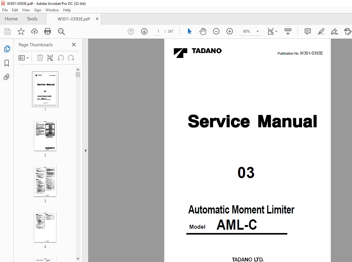
Tadano Faun Automatic Moment Limiter AML-C Service Manual – PDF DOWNLOAD
$28.95
Tadano Faun Automatic Moment Limiter AML-C Service Manual – PDF DOWNLOAD
Description
Tadano Faun Automatic Moment Limiter AML-C Service Manual – PDF DOWNLOAD
FILE DETAILS:
Tadano Faun Automatic Moment Limiter AML-C Service Manual – PDF DOWNLOAD
Language : English
Pages : 247
Downloadable : Yes
File Type : PDF
DESCRIPTION:
Tadano Faun Automatic Moment Limiter AML-C Service Manual – PDF DOWNLOAD
Foreword:
This service manual (this document) is compiled to provide information on the AML-C that is equipped on the crane. “Input/Output Signals of the AML System” in this document offers the general description on the electrical circuit of the crane.
- For the detailed electrical circuit, refer to the service manual (Circuit diagrams and Data) of each model. For the actual works, perform appropriate repair and service with referring to the separate operation and maintenance manual, parts catalog, and service manual of the applicable model.
- When part replacement is needed, refer to the parts catalog first to check the disassembly unit as well as the parts sales unit.
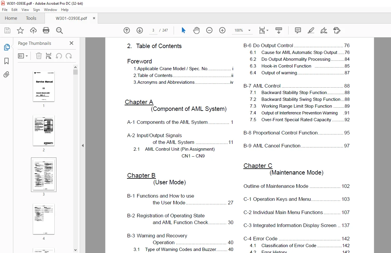
TABLE OF CONTENTS:
Tadano Faun Automatic Moment Limiter AML-C Service Manual – PDF DOWNLOAD
W301-0393E 1
Foreword 2
1 Applicable Crane Model / Spec No 2
2 Table of Contents 3
3 Acronyms and Abbreviations 5
(A) Components of AML System 6
A-1 Components of the AML System 7
1 1 System configuration 7
1 1 1 Diagram of the Main System 7
1 1 2 AML-C Block diagram 8
1 2 Display Unit 9
1 2 1 Display panel (LCD) 10
1 2 2 LED Display 12
1 2 3 Control switches 13
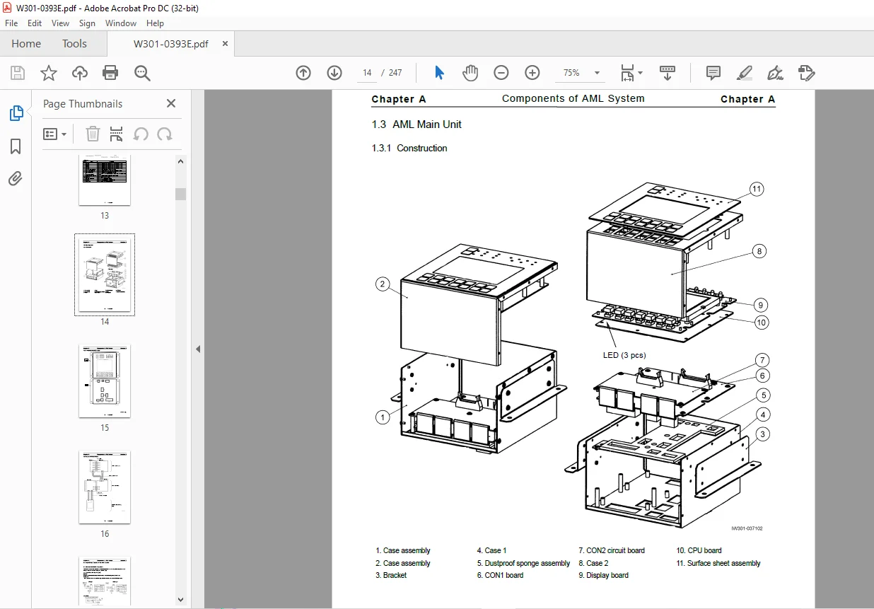
1 3 AML Main Unit 14
1 3 1 Construction 14
1 3 2 Panel outside view (CN1 – CN9) 15
1 3 3 Boards and Inner connectors 16
A-2 Input/Output Signals of the AML System 17
2 1 AML Control Unit (Pin Assignment) 17
2 1 1 Explanation of the Signals (Di, Do) 17
2 1 2 CN1 Connector (8-Pin) 18
2 1 3 CN2-1 Connector (20-Pin) 19
2 1 4 CN2-2 Connector (16-Pin) 21
2 1 5 CN3 Connector (12-Pin) 24
2 1 6 CN4 Connector (6-Pin) 25
2 1 7 CN5 Connector (16-Pin) 26
2 1 8 CN6 Connector (14-Pin) 29
2 1 9 CN7 Connector (20-Pin) 30
2 1 10 CN8 Connector (8-Pin) 32
2 1 11 CN9 (USB) Connector (4-Pin) 32
(B) User Mode 33
B-1 Functions and How to use the User Mode 36
1 1 Mode Structure 36
1 2 Display Selection 36
1 3 Operation Indicator Display 37
B-2 Registration of Operating State and AML Function Check 39
2 1 Engage the PTO 39
2 2 Registration of Outrigger State 40
2 3 Registration of Crane State 43
2 4 Registration of Number of Part-lines of Wire Rope 45
2 5 Pre-operational Inspection on AML 47
B-3 Warning and Recovery Operation 49
3 1 Type of Warning Codes and Buzzer 49
3 2 Warning Code and Crane Model Comparison Table 50
3 3 Warning code and Remedy List 51
3 3 1 GR-120N-2 51
3 3 2 GR-160N-2 54
3 3 3 GR-250N-2 57
3 3 4 GR-600N-2 60
B-4 Useful New Functions 63
4 1 Working Range Limit Function 63
4 1 1 State Display of Limit Function 64
4 1 2 Registration of Boom Angle, Lifting Height, and Load Radius Limit Function 64
4 1 3 Registration of Swing Range Limit Function 66
4 1 4 Alarm for Work Range Limit and Recovery Operation 67
4 2 The TARE Function 68
4 3 Mute Alarm Function 68
4 4 Fuel Consumption Indicator 69
4 5 Selection of Front Special Capacity 70
4 6 User Preset Menu 72
4 6 1 Preset menu/model comparison table 72
4 6 2 Selection of User Preset Menu 72
4 6 3 Eco Mode Selection 73
4 6 4 Elevating Speed Adjusting Function 74
4 6 5 Initialization of hook block position 76
4 6 6 Selection of Winch Drum Rotation Buzzer 77
4 6 7 Fuel Consumption History Display 78
4 6 8 Selection of Boom Elevation Slow Stop/Cancel 79
4 6 9 Contrast Adjustment of Display Panel 80
4 6 10 Maintenance Telescoping Mode 81
B-5 Action against AML System Error 83
5 1 Standard Spec 83
5 2 Korean spec 84
B-6 Do Output Control 85
6 1 Cause for AML Automatic Stop Output 85
6 1 1 100% Lifting Performance Stop 86
6 1 2 Overwinding Stop 87
6 1 3 Backward Stability Stop 87
6 1 4 Boom Upper Limit Stop 87
6 1 5 Boom Lower Limit Stop 88
6 1 6 Lifting Height Limit Stop 88
6 1 7 Load radius Limit Stop 88
6 1 8 Automatic Stop by Unlock the Jib Fixing Pin 89
6 1 9 Jib Fall Prevention Stop 90
6 1 10 Elevation Lower Limit 91
6 1 11 Elevation Upper Limit 92
6 1 12 Stop by Midair Extension Jib Tension Rod Interference 92
6 2 Do Output Abnormality Processing 93
6 3 Hook-in Control Function 94
6 3 1 Outline of Hook-in Control Function 94
6 3 2 Data Specification 95
6 3 3 Hook-in Possibility Judgment 95
6 3 4 Input/Output 95
6 4 Output of warning 96
6 4 1 Safety signal 96
6 4 2 90% warning 96
6 4 3 100% warning 96
B-7 AML Control 97
7 1 Backward Stability Stop Function 97
7 1 1 Outline of Function 97
7 1 2 Restriction Contents 97
7 2 Backward Stability Swing Stop Function 97
7 2 1 Outline of Function 97
7 2 2 Restriction Contents 97
7 3 Working Range Limit Stop Function 98
7 3 1 Outline of Function 98
7 3 2 Restriction Contents 98
7 3 3 Cancel Condition 99
7 3 4 Storing of Setting Condition 99
7 4 Output of Interference Prevention Warning 100
7 4 1 Function 100
7 4 2 Data Specification 100
7 4 3 Input 100
7 4 4 Warning Condition 100
7 4 5 Warning Code 100
7 5 Over-Front Special Rated Capacity 101
7 5 1 Name, Area and Mode 101
7 5 2 S Capacity Mode Shift Condition 101
7 5 3 Display 102
7 5 4 S Capacity Selection 103
7 5 5 Canceling the S Capacity 103
B-8 Proportional Control Function 104
8 1 Factors for Control 104
8 2 Valve adjustment (Characteristics Measurement) 104
8 3 Elevation Slow Stop 105
8 4 Swing Slow Stop 105
B-9 AML Cancel Function 106
9 1 Introduction 106
9 2 Canceling Method 107
9 2 1 Cancel Status Judgment 107
9 2 2 Cancel Switch Abnormality Judgment 107
9 3 Interlock Stop 108
9 3 1 Cancel Contents 108
9 4 Overload Cancel 108
9 4 1 Cancel Contents 108
9 5 Detector Abnormality 109
9 5 1 Stop Processing at Detector Abnormality (Compulsory unload output) 109
9 6 User preset menu 110
(C) Maintenance Mode 111
Outline of Maintenance Mode 113
C-1 Operation Keys and Menu 114
1 1 Operation Keys 114
1 2 Structure of Maintenance Mode Menu 115
1 3 Mode Shift and Menu Structure 116
1 3 1 Shift to Maintenance Mode 116
1 3 2 Menu Selection 116
1 3 3 Maintenance Main Menu Functions 117
C-2 Individual Main Menu Functions 118
2 1 ROM ID check 118
2 2 Di Check 119
2 3 Ai Check 120
2 4 Pi Check 121
2 5 Si Check 122
2 6 Do Check 124
2 7 Ao Check 125
2 8 MDT Check 126
2 8 1 Description of Display Contents 126
2 8 2 Operation Method 126
2 8 3 Selection of MDT Check Menu Item 127
2 8 4 MDT Check, Display of Upper Section Di Check State 128
2 8 5 MDT Check, Display of Upper Section Ai Check State 129
2 8 6 MDT Check, Display of Upper Section Do Check State 130
2 8 7 MDT Check, Display of Lower Section Di Check State 131
2 8 8 MDT Check, Display of Lower Section Ai Check State 132
2 8 9 MDT Check, Display of Lower Section Do Power Check State 133
2 8 10 MDT Check, Display of Lower Section Do Check State 134
2 8 11 MDT Check, Display of Lower Section Ao Check State 135
2 8 12 MDT Check, Display of Pi Check State 136
2 9 System Voltage Check 137
2 10 Error History Display 138
2 11 Erasing Error History 139
2 12 Latest Overload History Display 140
2 13 Maximum Overload History Display 141
2 14 Clock Adjustment 142
2 15 Unit Selection 144
2 16 Language Selection 145
2 17 AML Emergency Switch History Display 146
2 18 Meter Adjustment 147
C-3 Integrated Information Display Screen 148
3 1 Crane Information Display Screen 148
3 2 Vehicle Information Display Screen 148
3 3 Display Contents 149
3 4 Vehicle Error Information 152
C-4 Error Code 153
4 1 Classification of Error Code 153
4 2 Error History 153
4 3 Error Notification 154
4 4 Error Code Table 155
4 4 1 Communication Device Error (Transmitter, etc ) 155
4 4 2 Detector Abnormality or Abnormal Combination of Detectors 158
4 4 3 AML Internal Abnormality (System Abnormality) 163
4 5 CPU State Indicator LED 164
C-5 Required Adjustment after AML System Part Replacement 165
C-6 Disassembly and Assembly 166
6 1 Disassembly of AML Main Unit 166
6 2 Connector 167
6 2 1 Removing and attaching the connector contact 167
6 2 2 Crimping receptacle contact 179
6 3 Replacing the Clock Battery 180
(D) Adjustment Mode 181
Outline of Adjustment Mode 183
D-1 Operation Keys and Menu 184
1 1 Operation Keys 184
1 2 Structure of Maintenance Mode Menu 185
1 3 Mode Shift 186
1 3 1 Shift to Maintenance Mode 186
1 3 2 Menu Selection 186
1 3 3 Shift to Adjustment Mode 187
1 3 4 Adjustment Main Menu 188
D-2 Detector Adjustment 189
2 1 Length and Angle Adjustment Screen 189
2 2 Boom Length Adjustment 190
2 2 1 Boom Length Zero Adjustment 190
2 2 2 Boom Length Span Adjustment 190
2 2 3 Adjustment Check 190
2 3 Boom Angle Adjustment 191
2 3 1 Boom Angle Zero Adjustment 191
2 3 2 Boom Angle Span Adjustment 191
2 3 3 Adjustment Check 191
2 4 Swing Angle Adjustment 192
2 4 1 Swing Angle 1 Zero Adjustment 192
2 4 2 Swing Angle 2 Zero Adjustment 192
2 4 3 Swing Angle 1 Span Adjustment 193
2 4 4 Swing Angle 2 Span Adjustment 193
2 4 5 Adjustment Check 193
2 5 Outrigger Length Adjustment 194
2 5 1 Outrigger Length Zero Adjustment 194
2 5 2 Outrigger Length Span Adjustment 195
2 5 3 Adjustment Check 195
2 6 Jib Length Detector Adjustment 196
2 6 1 Jib Length Zero Adjustment 196
2 6 2 Jib Length Span Adjustment 196
2 6 3 Adjustment Check 196
2 7 Jib offset Angle Adjustment (Offset angle to Boom) 197
2 7 1 Jib offset angle Zero Adjustment 197
2 7 2 Jib offset angle Span Adjustment 197
2 7 3 Adjustment Check 197
2 8 Moment / Load Radius Adjustment 198
2 8 1 Moment Zero Adjustment 199
2 8 2 Moment Span Preliminary / Load Radius Adjustment 199
2 8 3 Moment Span Adjustment 200
2 8 4 Moment Adjustment Check 200
D-3 Valve Adjustment 201
3 1 Adjustment Sub Menu 201
3 2 Swing Output Adjustment (Offset Method) 202
3 3 Swing Output Adjustment (Characteristics Measurement Method) 203
3 3 1 Adjustment Procedure 203
3 4 Elevating / Telescoping Output Adjustment 205
3 5 Function of Slow Stop 206
3 5 1 Elevation Slow Stop 206
3 5 2 Swing Slow Stop 206
D-4 Operation History Erase 207
4 1 Operation Procedure 207
D-5 Option Select 208
5 1 Operation Procedure 208
5 2 Processing Depending on Setting Status 209
5 3 Processing at Setting without Detector 209
5 4 Processing at Setting without Function 210
D-6 Jib Tilt Full Retraction Storing 211
6 1 Operation Procedure 211
D-7 AML Emergency / Override Switch History Erase 214
7 1 Operation Procedure 214
7 2 Operating Conditions 214
(E) Information and Data 215
E-1 AML Adjustment Value List 217
1 1 Applicable Model: GR-120N-2 217
1 1 1 Initial Adjustment 217
1 1 2 Detector Adjustment 217
1 1 3 Slow Stop Adjustment 218
1 1 4 Option Setting 218
1 1 5 Setting Item after Adjustment 218
1 2 Applicable Model: GR-160N-2 219
1 2 1 Initial Adjustment 219
1 2 2 Detector Adjustment 219
1 2 3 Slow Stop Adjustment 220
1 2 4 Setting Item after Adjustment 220
1 3 Applicable Model: GR-250N-2 221
1 3 1 Initial Adjustment 221
1 3 2 Detector Adjustment 221
1 3 3 Slow Stop Adjustment 222
1 3 4 Option Setting 222
1 3 5 Drum Position Adjustment 222
1 3 6 Setting Item after Adjustment 222
1 4 Applicable Model: GR-600N-2 223
1 4 1 Initial Adjustment 223
1 4 2 Detector Adjustment 223
1 4 3 Slow Stop Adjustment 224
1 4 4 Drum Position Adjustment 224
1 4 5 Option Setting 225
1 4 6 Setting Item after Adjustment 225
E-2 Detector Check 226
2 1 Applicable Model: GR-120N-2 226
2 1 1 Boom Length Detector 226
2 1 2 Boom Angle Detector 226
2 1 3 Swing Angle Detector 227
2 1 4 Outrigger Extension Length Detector 227
2 1 5 Pressure Sensor for Moment Detection 228
2 1 6 Jib Angle Detector (PT Jib Specification) 228
2 2 Applicable Model: GR-160N-2 229
2 2 1 Boom Length Detector 229
2 2 2 Boom Angle Detector 229
2 2 3 Swing Angle Detector 230
2 2 4 Outrigger Extension Length Detector 230
2 2 5 Pressure Sensor for Moment Detection 231
2 3 Applicable Model: GR-250N-2 232
2 3 1 Boom Length Detector 232
2 3 2 Boom Angle Detector 232
2 3 3 Swing Angle Detector 233
2 3 4 Outrigger Extension Length Detector 233
2 3 5 Pressure Sensor for Moment Detection 234
2 3 6 Jib Angle Detector (PT Jib Specification) 234
2 4 Applicable Model: GR-600N-2 235
2 4 1 Boom Length Detector 235
2 4 2 Boom Angle Detector 235
2 4 3 Swing Angle Detector 236
2 4 4 Outrigger Extension Length Detector 236
2 4 5 Pressure Sensor for Moment Detection 237
2 4 6 Jib Angle Detector 237
2 4 7 Jib Length Detector 238
E-3 AML Control Function List 239
3 1 Applicable Model: GR-120N-2 239
3 2 Applicable Model: GR-160N-2 240
3 3 Applicable Model: GR-250N-2 241
3 4 Applicable Model: GR-600N-2 242
E-4 AML Input/Output List 243
4 1 Applicable Model: GR-120N-2 243
4 2 Applicable Model: GR-160N-2 244
4 3 Applicable Model: GR-250N-2 245
4 4 Applicable Model: GR-600N-2 246
History of revision 247
IMAGES PREVIEW OF THE MANUAL:
Contact us: [email protected]
PLEASE NOTE:
- This is the SAME exact manual used by your dealers to fix your vehicle.
- The same can be yours in the next 2-3 mins as you will be directed to the download page immediately after paying for the manual.
- Any queries / doubts regarding your purchase, please feel free to contact [email protected]
S.V