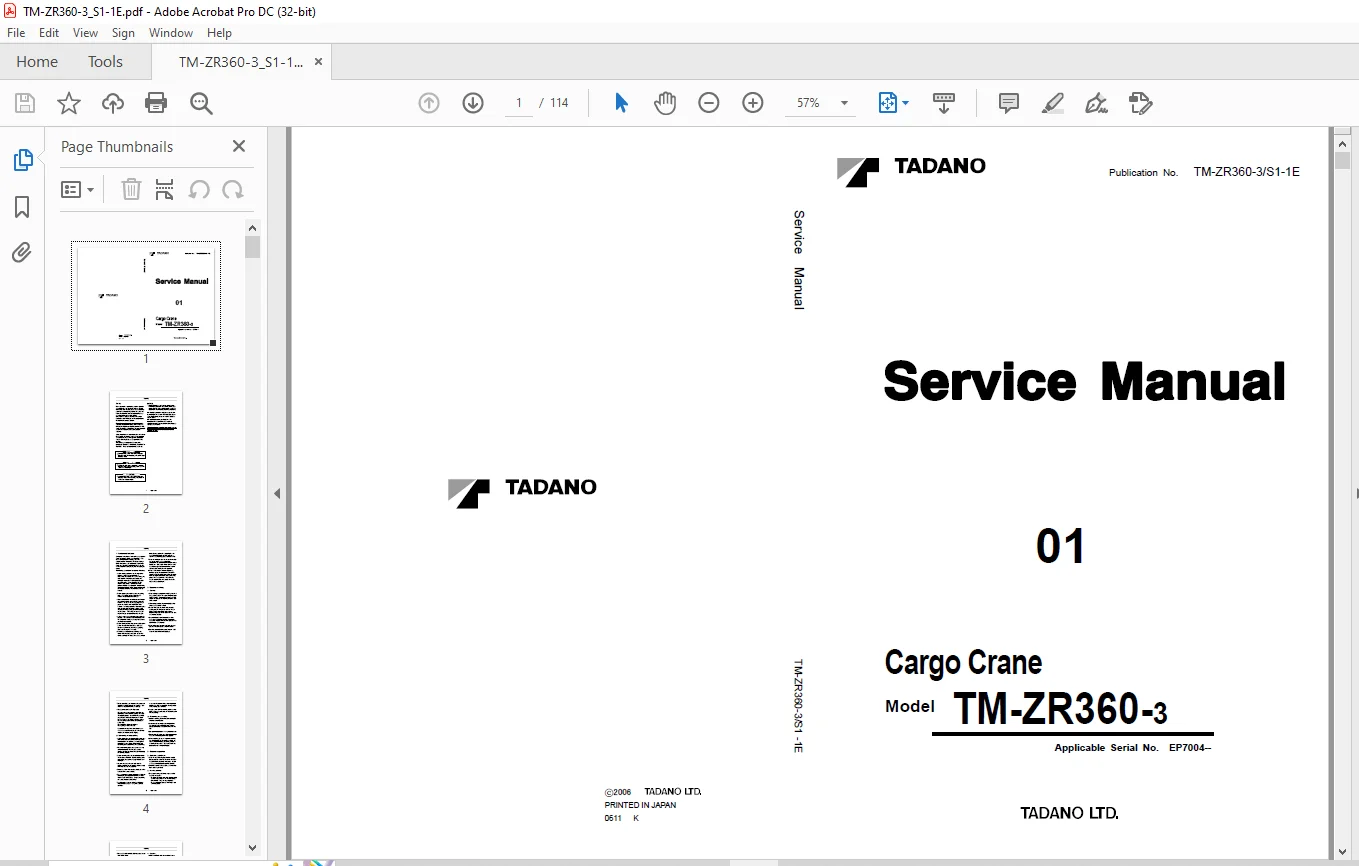
Tadano Faun Cargo Crane TM-ZR360-3 Service Manual SN EP7004 – PDF DOWNLOAD
$26.95
Tadano Faun Cargo Crane TM-ZR360-3 Service Manual SN EP7004 – PDF DOWNLOAD
Description
Tadano Faun Cargo Crane TM-ZR360-3 Service Manual SN EP7004 – PDF DOWNLOAD
FILE DETAILS:
Tadano Faun Cargo Crane TM-ZR360-3 Service Manual SN EP7004 – PDF DOWNLOAD
Pages : 114
File Type : PDF
DESCRIPTION:
Tadano Faun Cargo Crane TM-ZR360-3 Service Manual SN EP7004 – PDF DOWNLOAD
Safety:
Most accidents that occur during machine operation and maintenance are caused by failure to observe basic safety rules and precautions. Before operating your machine or performing maintenance, read and become familiar with all the safety precautions and recommendations given in this section.
- Remember that failure to observe even a single precaution could involve you and the people around the machine in a serious accident. Foreseeing potential dangers is vital for preventing accidents.
- All personnel working with the machine, including the supervisor, machine operator and oiler, should be sensitive to potentially dangerous situations and take the necessary measures to prevent accidents.
- Safety precautions and recommendations are outlined in this section and are also included in the operation and maintenance instructions given in subsequent sections. Warning labels are also provided on the machine.
1. Fundamental cautions
Servicemen inexperienced in the units of this machine should be cautious about safety operations. They must acquire sufficient knowledge about the equipment before dismounting and disassembling it. Before dismounting each component, a serviceman should read this service manual thoroughly and find out the weight of the component, then lift it by proper means.
The following are cautions to be observed all the time.
TABLE OF CONTENTS:
Tadano Faun Cargo Crane TM-ZR360-3 Service Manual SN EP7004 – PDF DOWNLOAD
TM-ZR360-3/S1-1E 1
Safety 2
1 Fundamental cautions 3
2 Cautions in working 3
2 1 General 3
2 2 Dismounting and disassembling 4
2 3 Remounting and assembling 4
3 Cautions in operation 4
3 1 Brake fluid replenishment 4
3 2 Handling of battery 4
3 3 Handling of radiator 5
3 4 Cooling fan 5
4 About waste disposal 5
4 1 Gasoline 5
4 2 Hydraulic oil 5
4 3 Motor oil 5
Foreword 6
1 Applicable unit No 6
2 Separate service manual 6
3 Outline of specifications 7
4 Conversion table 8
5 Contents 11
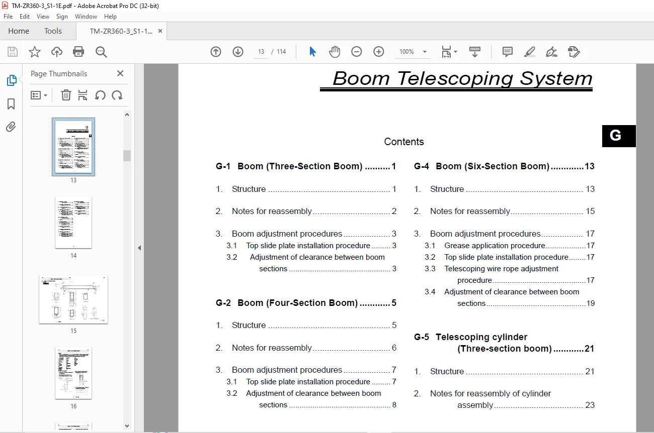
(G) Boom Telescoping System 13
G-1 Boom (Three-Section Boom) 15
1 Structure 15
2 Notes for reassembly 16
3 Boom adjustment procedures 17
3 1 Top slide plate installation procedure 17
3 2 Adjustment of clearance between boom sections 17
G-2 Boom (Four-Section Boom) 19
1 Structure 19
2 Notes for reassembly 20
3 Boom adjustment procedures 21
3 1 Top slide plate installation procedure 21
3 2 Adjustment of clearance between boom sections 22
G-3 Boom (Five-Section Boom) 23
1 Structure 23
2 Notes for reassembly 24
3 Boom adjustment procedures 25
3 1 Top slide plate installation procedure 25
3 2 Adjustment of Clearance between Boom Sections 26
G-4 Boom (Six-Section Boom) 27
1 Structure 27
2 Notes for reassembly 29
3 Boom adjustment procedures 31
3 1 Grease application procedure 31
3 2 Top slide plate installation procedure 31
3 3 Telescoping wire rope adjustment procedure 31
3 4 Adjustment of clearance between boom sections 32
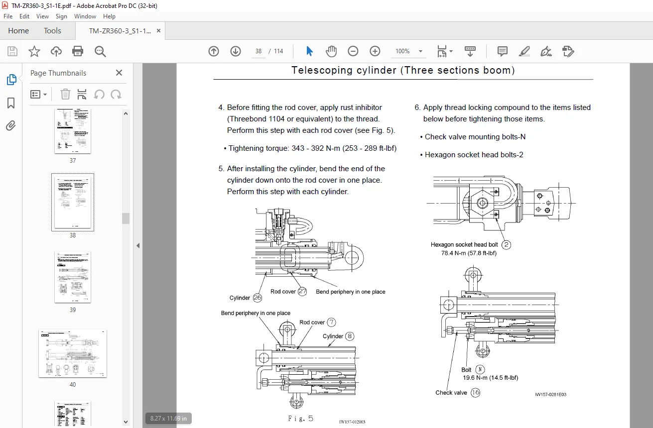
G-5 Telescoping cylinder (Three-section boom) 35
1 Structure 35
2 Notes for reassembly of cylinder assembly 37
G-6 Telescoping Cylinder (Four-Section Boom) 39
1 Structure 39
2 Description of operation 42
2 1 Control of telescoping sequence 42
2 2 Shock-absorbing mechanism of No 2 cylinder 42
3 Notes for reassembly of cylinder assembly 43
4 Notes for reassembly of telescoping cylinder 45
5 Cautions about telescoping wire rope adjustment 46
6 Telescoping wire rope adjustment procedure 47
6 1 Wire rope adjustment with the telescoping cylinder out of the boom 47
6 2 Wire rope adjustment with the telescoping cylinder installed in the boom 49
G-7 Telescoping Cylinder (Five-Section Boom) 50
1 Structure 50
2 Description of operation 53
2 1 Control of telescoping sequence 53
2 2 Shock-absorbing mechanism of No 3 cylinder 54
3 Notes for reassembly of cylinder assembly 55
4 Notes for reassembly of telescoping cylinder 58
5 Telescoping wire rope adjustment procedure 59
5 1 Wire rope adjustment with the telescoping cylinder out of the boom 60
5 2 Wire rope adjustment with the telescoping cylinder installed in the boom 62
G-8 Telescoping Cylinder (Six-Section Boom) 63
1 Structure 63
2 Description of operation 66
2 1 Control of telescoping sequence 66
2 2 Shock-absorbing mechanism of No 3 cylinder 67
3 Notes for reassembly of cylinder assembly 68
4 Notes for reassembly of telescoping cylinder 71
(H) Safety System 73
H-1 Overload Prevention Device (AML) 74
1 Structure 74
2 Function of components 75
3 Caution about installing length detector 76
4 AML adjustment 77
4 1 Attention for adjustment work 77
4 2 AML components 78
4 3 Selecting the crane model and capacity data 79
4 4 Zero-point and span adjustments of length detector 81
4 5 Zero-point and span adjustments of angle detector 81
4 6 Confirming accuracy 82
5 List of error Nos related to AML 83
6 Adjustment items when parts are exchanged 84
H-2 Length Detector (Boom) 85
1 Structure 85
2 Specifications 85
H-3 Angle Detector (Boom) 86
1 Structure 86
2 Specifications (potentiometer) 86
(V) Radio Control System 87
V-1 Configurations of Radio-control System 88
1 Structure 88
2 Safety functions of radio-control system 90
2 1 Automatic power off function 90
2 2 Fail-safe function 90
2 3 Receiving condition alarm 90
2 4 Alarm function 91
V-2 Radio-control Valve 93
1 Structure 93
1 1 Hydraulic circuit 93
1 2 Electric circuit 94
1 3 General View 95
1 4 Cross section 96
V-3 Measures for Emergency Case 98
1 When radio-control mode operation is not available 98
2 When neither radio nor manual control mode operations are available 100
3 Troubleshooting guide 101
(Y) Data, Adjustment and Checks 104
Y-1 Service Data 105
1 Set pressure 105
2 Hydraulic units 105
Y-2 Adjustment (Hydraulic) 106
1 Adjusting relief valve pressure 106
1 1 Main relief valve 106
Y-3 Adjustment (Electric) 107
1 Adjustment of outrigger part detecting switch 107
1 1 Checking outrigger extension state and installing state detecting switches 107
1 2 Adjustment of outrigger extension state and installing state detecting switches 107
2 Adjustment of right and left zone detecting ranges 109
(Z) System Diagrams 110
Z-1 Hydraulic Circuit 111
Z-2 Electric Circuit 112
1 Applicable serial No : — EP9035 112
2 Applicable serial No : EP9036 — 113
History of revision 114
IMAGES PREVIEW OF THE MANUAL:
Questions? Email us: [email protected]
https://vimeo.com/839722092?share=copy
PLEASE NOTE:
- This is the SAME MANUAL used by the dealerships to diagnose your vehicle
- No waiting for couriers / posts as this is a PDF manual and you can download it within 2 minutes time once you make the payment.
- Your payment is all safe and the delivery of the manual is INSTANT – You will be taken to the DOWNLOAD PAGE.
- So have no hesitations whatsoever and write to us about any queries you may have : heydownloadss @gmail.com
S.V