Tadano Faun Overload Prevention Device AML-LIIB Service Manual – PDF DOWNLOAD
$28.95
Tadano Faun Overload Prevention Device AML-LIIB Service Manual – PDF DOWNLOAD
Description
Tadano Faun Overload Prevention Device AML-LIIB Service Manual – PDF DOWNLOAD
FILE DETAILS:
Tadano Faun Overload Prevention Device AML-LIIB Service Manual – PDF DOWNLOAD
Language : English
Pages : 285
Downloadable : Yes
File Type : PDF
DESCRIPTION:
Tadano Faun Overload Prevention Device AML-LIIB Service Manual – PDF DOWNLOAD
Foreword:
This service manual covers the Overload prevention device (AML) installed on the TADANO cranes in the chart below.
- In undertaking repair, refer to the separate operation and maintenance manual, parts catalog, and crane-covering service manual for pertinent information.
- If the parts replacement is required, check the disassembly and order units from the applicable parts catalog.
TABLE OF CONTENTS:
Tadano Faun Overload Prevention Device AML-LIIB Service Manual – PDF DOWNLOAD
W301-0217E 1
Foreword 2
1 Applicable Spec No 2
2 Contents 3
Components of the AML Main Unit 7
1 Panel 7
2 Internal view and name plate 8
3 Internal block diagram 8
Diagram of the AML System (GT-550E-1) 10
Input/Output Signals of the AML System (GT-550E-1) 10
Diagram of the AML System (GR-120N-1) 18
Input/Output Signals of the AML System (GR-120N-1) 19
Diagram of the AML System (GR-700E-1/GR-550E-1) 32
Input/Output Signals of the AML System (GR-700E-1/GR-550E-1) 33
Diagram of the AML System (GR-300E-1) 44
Input/Output Signals of the AML System (GR-300E-1) 45
Diagram of the AML System (GT-700E-1) 52
Input/Output Signals of the AML System (GT-700E-1) 53
Diagram of the AML System (GT-800E-1) 61
Input/Output Signals of the AML System (GT-800E-1) 62
[OPERATION] 71
Functions of and How to Use UserMode (GT-550E-1) 71
Mode Structure 71
Configuration and Functions of the AMLSystem 72
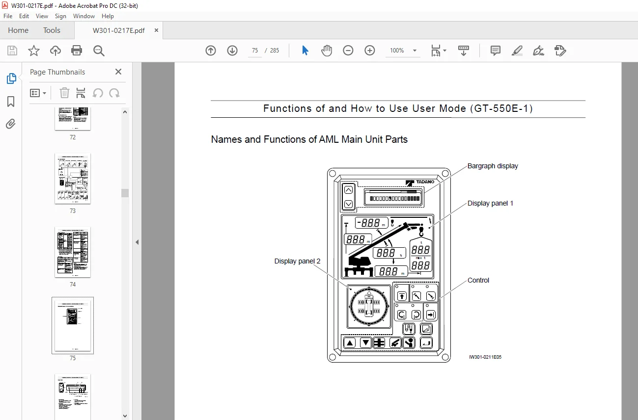
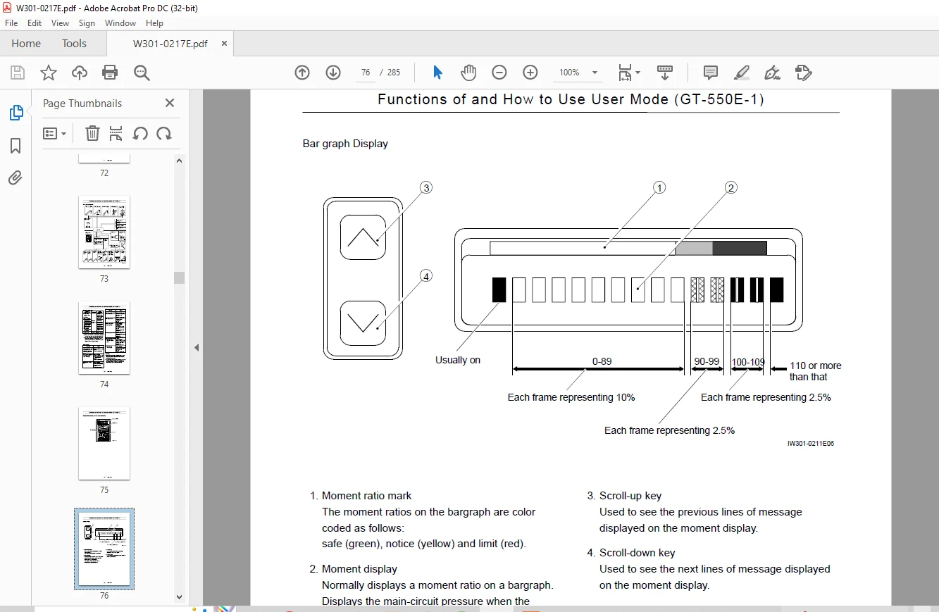
Names and Functions of AML Main Unit Parts 75
Selecting Operational Status 81
AML Pre-operational Inspection 84
How to Use the Working Range LimitFunction 85
Display Alteration 89
Functions of and How to Use UserMode (GR-120N-1) 90
Mode Structure 90
Configuration and Functions of the AMLSystem 91
Names and Functions of AML Main Unit Parts 94
Selecting Operational Status 100
AML Pre-operational Inspection 104
How to Use the Working Range LimitFunction 104
How to Use the Elevation SpeedAdjustment Function 107
Display Alteration 109
Functions of and How to Use UserMode (GR-700E-1/GR-550E-1) 110
Mode Structure 110
Configuration and Functionsof the AML System 111
Names and Functions of AML Main Unit Parts 115
Selecting Operational Status 121
Selecting Winch Condition 126
Selecting Jib Mounted Condition 126
AML Pre-operational Inspection 127
How to Use the Working Range LimitFunction 128
Display Alteration 132
Functions of and How to Use UserMode (GR-300E-1) 133
Mode Structure 133
Configuration andFunctions of the AML System 134
Names and Functions of AML Main Unit Parts 138
Selecting Operational Status 144
Selecting Jib Mounted Condition 148
AML Pre-operational Inspection 149
How to Use the Working Range LimitFunction 150
Display Alteration 154
Functions of and How to Use User Mode(GT-700E-1) 155
Mode Structure 155
Configuration and Functions of the AML System 156
Names and Functions of AML Main Unit Parts 159
Selecting Operational Status 165
Selecting Winch Condition 169
Selecting Jib Mounted Condition 169
AML Pre-operational Inspection 170
How to Use the Working Range LimitFunction 171
Display Alteration 175
Functions of and How to Use UserMode (GT-800E-1) 176
Mode Structure 176
Configuration and Functionsof the AML System 177
Names and Functions of AML Main Unit Parts 180
Selecting Operational Status 186
Selecting Winch Condition 190
Selecting Jib Mounted Condition 190
AML Pre-operational Inspection 191
Display Alteration 196
[ADJUSTMENT AND MAINTENANCE] 197
General: Adjustment Mode and Maintenance Mode 197
1 Keys and Switches for Adjustment and Maintenance 197
2 Mode Structure and Menu 198
3 Method of Shifting Modes 200
4 Method of Menu Selection 201
Required Adjustment After AML System Parts Replacement 202
Functions of andHow to Use Adjustment Mode 203
Adjustment Procedures 203
1 Adjustment Initialization 204
1 1 Procedure of Conversion Factors Resetting 204
1 2 Procedures of Moment AdjustmentResetting 204
2 Capacity Setting 205
2 1 Procedure of Head-off Capacity Setting 205
2 2 Procedure of Jib Selection 206
2 3 Procedure of Single Top Selection 206
2 4 Procedure of Winch Drum Position Setting 207
3 Boom Length Adjustment 208
4 Boom Angle Adjustment 209
5 Swing Angle Adjustment 210
6 Outrigger Extension Width Adjustment 211
7 Moment Adjustment 212
7 1 Moment Zero-point Adjustment 213
7 2 Moment Span Preliminary Adjustment 214
7 3 Moment Zero-point Check andFine Adjustment 214
7 4 Load Radius Adjustment 215
7 5 Moment Span Fine Adjustment 215
7 6 Moment Zero-point Recheck 216
8 Clock Adjustment 217
9 Adjustment of Swing Output 218
9 1 Procedure of Resetting Ao Offset Value 218
9 2 Adjustment of Swing Output(Ao offset adjustment) 218
10 Adjustment of Elevation Output 220
10 1 Procedure of Resetting Elevation Data 220
10 2 Adjustment of Elevation Output(elevation speed adjustment) 220
Other Functions and How to Use Them 222
1 Language 222
2 Overload History Display 222
3 Erasing the Overload History 223
Functions of andHow to Use Maintenance Mode 224
1 Program Version Display 225
2 Data ID Number Display 225
3 Di Check 225
4 Ai Check 226
5 Elevating Cylinder Oil PressureMonitor 226
6 Do Check 227
7 MDT (Multiplex Data Transmitter)Monitor 227
8 Key Switch Check 229
9 Display Check 229
10 Error Data Display 229
11 Erasing the Error Data 230
12 Option Board Check 230
13 Ao Check 230
14 Sio Check 231
15 Adjust Monitor 231
16 Overload History Display 231
17 Erasing the Overload History 231
18 Clock Adjustment 231
Error Message 232
1 Display of Error Message 232
2 How to Read the Error Message 232
3 How to Read the Error History 232
4 Troubleshooting Table 233
4 1 Group Code 0 233
4 2 Group Code 1 242
4 3 Group Code 2 244
4 4 Group Code 3 247
Disassembly of AML Main Unit 248
1 Removing Front Panel/Display Board 248
2 Removing Rear Panel/ConnectorBoard/Current Output Board 248
3 Removing CPU Board/Analog Board/Power Board 249
3 1 Notes on ROM/EEPROM Replacement 249
[INFORMATION AND DATA] 250
Adjustment Value Table 250
Specification No : GT-550E-1-10102, 10302, 00102 250
Specification No : GT-550E-1-10202, 10402, 00202 250
Specification No : GR-120N-1-00103 252
Specification No : GR-700E-1-00101,00211 254
Specification No : GR-700E-1-00102,00212 254
Specification No : GR-300E-1-00201, 00211 (2M2D-specification) 256
Specification No : GR-300E-1-00202, 00212 (2M2D-specification) 256
Specification No : GR-300E-1-00203, 00213 (1M1D and without jib-specification) 256
Specification No : GR-550E-1-00211 258
Specification No : GR-550E-1-00212 258
Specification No : GT-700E-1-90102 (2M2D-specification) 260
Specification No : GT-800E-1-90102 (2M2D-specification) 262
Checking the Detectors (GT-550E-1) 264
1 Boom Length Detector 264
2 Boom Angle Detector 265
3 Swing Angle Detector 266
4 Outrigger Extension Width Detector 266
5 Pressure Sensor for MomentDetection 267
Checking the Detectors(GR-120N-1/GR-700E-1/GR-550E-1) 268
1 Boom Length Detector 268
2 Boom Angle Detector 269
3 Swing Angle Detector 270
4 Outrigger Extension Width Detector 270
5 Pressure Sensor for MomentDetection 271
Checking the Detectors(TR-300E-1) 272
1 Boom Length Detector 272
2 Boom Angle Detector 273
3 Swing Angle Detector 274
4 Outrigger Extension Width Detector 274
5 Pressure Sensor for MomentDetection 275
Checking the Detectors(GT-700E-1) 276
1 Boom Length Detector 276
2 Boom Angle Detector 277
3 Swing Angle Detector 278
4 Outrigger Extension Width Detector 278
5 Pressure Sensor for MomentDetection 279
Checking the Detectors(GT-800E-1) 280
1 Boom Length Detector 280
2 Boom Angle Detector 280
3 Swing Angle Detector 281
4 Outrigger Extension Width Detector 281
5 Pressure Sensor for MomentDetection 282
Fuses 283
Replacing the Clock Battery 284
History of revision 285
IMAGES PREVIEW OF THE MANUAL:
Need help? Contact: [email protected]
PLEASE NOTE:
- This is the SAME MANUAL used by the dealerships to diagnose your vehicle
- No waiting for couriers / posts as this is a PDF manual and you can download it within 2 minutes time once you make the payment.
- Your payment is all safe and the delivery of the manual is INSTANT – You will be taken to the DOWNLOAD PAGE.
- So have no hesitations whatsoever and write to us about any queries you may have : heydownloadss @gmail.com
S.V