Repair Manual for Tadano Faun GR-300EX-2 Crane SN 561384 PDF Download
$29.95
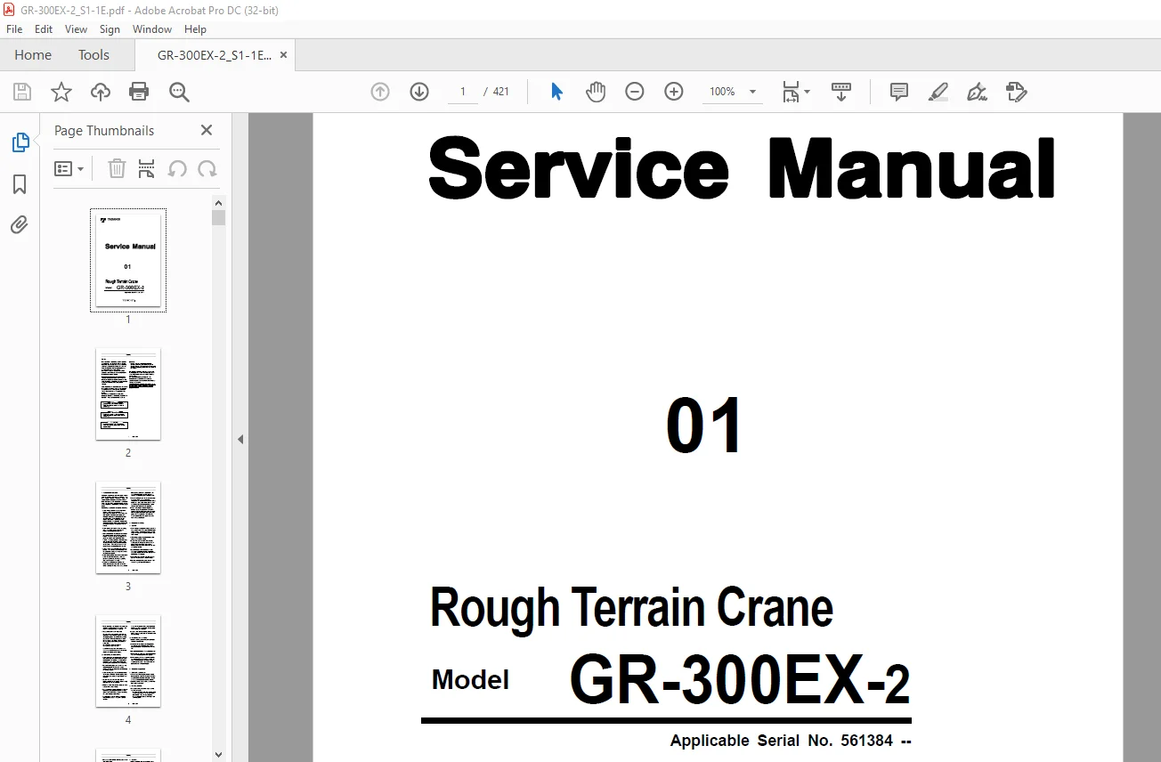
Tadano Faun Rough Terrain Crane GR-300EX-2 Service Manual SN 561384 – PDF DOWNLOAD
Description
Tadano Faun Rough Terrain Crane GR-300EX-2 Service Manual SN 561384 – PDF DOWNLOAD
FILE DETAILS:
Tadano Faun Rough Terrain Crane GR-300EX-2 Service Manual SN 561384 – PDF DOWNLOAD
Language : English
Pages : 421
Downloadable : Yes
File Type : PDF
TABLE OF CONTENTS:
Tadano Faun Rough Terrain Crane GR-300EX-2 Service Manual SN 561384 – PDF DOWNLOAD
GR-300EX-2 1
Safety 2
1 Fundamental cautions 3
2 Cautions in working 3
2 1 General 3
2 2 Dismounting and disassembling 4
2 3 Remounting and assembling 4
3 Cautions in operation 4
3 1 Brake fluid replenishment 4
3 2 Handling of battery 4
3 3 Handling of radiator 5
3 4 Cooling fan 5
4 About waste disposal 5
4 1 Gasoline 5
4 2 Hydraulic oil 5
4 3 Motor oil 5
Foreword 6
1 Applicable spec and serial number 6
2 Separate service manual 6
3 External view 7
4 Conversion table 8
5 Outline of specifications 10
6 Group index 12
7 Contents 13
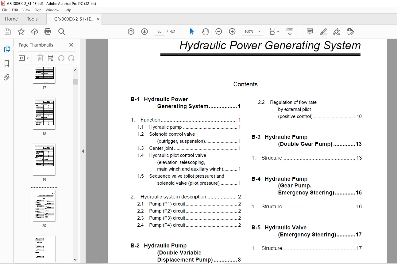
(B) Hydraulic Power Generating System 20
B-1 Hydraulic Power GeneratingSystem 22
1 Function 22
1 1 Hydraulic pump 22
1 2 Solenoid control valve(outrigger, suspension) 22
1 3 Center joint 22
1 4 Hydraulic pilot control valve(elevation, telescoping, main winch and auxiliary winch) 22
1 5 Sequence valve (pilot pressure) and solenoid valve (pilot pressure) 22
2 Hydraulic system description 23
2 1 Pump (P1) circuit 23
2 2 Pump (P2) circuit 23
2 3 Pump (P3) circuit 23
2 4 Pump (P4) circuit 23
B-2 Hydraulic Pump (Double Variable Displacement Pump) 24
1 Structure 24
1 1 General view 24
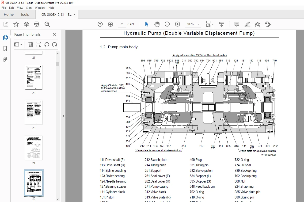
1 2 Pump main body 25
1 3 Regulator 26
2 Operation 28
2 1 Regulation of flow rate by discharging pressure 28
2 2 Regulation of flow rate by external pilot(positive control) 31
B-3 Hydraulic Pump (Double Gear Pump) 34
1 Structure 34
B-4 Hydraulic Pump (Gear Pump, Emergency Steering) 37
1 Structure 37
B-5 Hydraulic Valve (Emergency Steering) 38
1 Structure 38
B-6 Center Joint 40
1 Structure 40
1 1 General view 40
1 2 Port size table 42
1 3 Swivel joint (hydraulics and pneumatics) 43
1 4 Swivel joint (heated water) 45
2 Slip ring 46
2 1 General view 46
2 2 Harness and connector 47
2 3 Maintenance of ring and brush 47
B-7 Hydraulic Pilot Control Valve (Elevating, Telescoping, Winch) 48
1 Structure 48
B-8 Sequence Valve (Pilot Pressure) 59
1 Structure 59
B-9 Solenoid Valve (Pilot Pressure) 62
1 Structure 62
B-10 Solenoid Valve (Positive Control) 64
1 Structure 64
B-11 Check Valve (Gauge lsolator) 66
1 Structure 66
(C) Outrigger System 67
C-1 Outrigger System 68
1 Function 68
1 1 Solenoid control valve (outrigger, suspension) 68
1 2 Solenoid valve (slide/jack) 68
1 3 Jack cylinder 68
1 4 Pilot check valve (jack cylinder retraction prevention) 68
1 5 Extension cylinder 68
1 6 Check valve (slide/jack extension prevention) 68
2 Hydraulic system description 68
2 1 Outrigger extension operation 68
2 2 Outrigger retraction operation 68
3 Electric system 69
3 1 Outrigger operation inside operation cab 69
C-2 Solenoid Control Valve (Outrigger, Suspension) 70
1 Structure 70
1 1 General view 70
1 2 Body assy (outrigger) 72
1 3 Body assy (suspension) 74
1 4 P cover assy 76
1 5 T cover assy 79
1 6 Tandem plate assy 82
C-3 Solenoid Valve (Slide/Jack) 83
1 Structure 83
2 Solenoid valve assy 84
2 1 Solenoid valve (Rexroth(UCHIDA)) 84
2 2 Solenoid valve (TOKIMEC) 85
2 3 Solenoid valve (NACHI) 86
C-4 Jack Cylinder 87
1 Structure 87
C-5 Pilot check Valve (Jack Cylinder Retracting Prevention) 88
1 Structure 88
C-6 Extension Cylinder 89
1 Structure 89
C-7 Check Valve (Slide/Jack Extending Prevention) 90
1 Structure 90
(D) Swing System 91
D-1 Swing System 92
1 Function 92
1 1 Swing drive unit (hydraulic motor and swing speed reducer) 92
1 2 Hydraulic pilot control valve (swing) 92
1 3 Solenoid valve (swing brake release) 92
1 4 Swing free function 92
2 Hydraulic system description 92
D-2 Hydraulic Pilot Control Valve (Swing) 93
1 Structure 93
D-3 Hydraulic Motor (Swing) 99
1 Structure 99
D-4 Swing Speed Reducer 101
1 Structure 101
2 Removing of hydraulic motor 102
3 Disassembly of reducer 102
4 Assembly of reducer 103
5 Installation of hydraulic motor 103
D-5 Swing Assembly 104
1 Structure 104
2 Swing bearing mounting bolt 105
2 1 Bearing inner ring bolts 105
2 2 Bearing outer ring bolts 106
(E) Boom Elevating System 107
E-1 Elevating System 108
1 Function 108
1 1 Elevating cylinder 108
1 2 Counterbalance valve 108
1 3 Pressure sensor 108
1 4 Elevation slow stop 108
2 Hydraulic system description 108
E-2 Elevating Cylinder 109
1 Structure 109
E-3 Counterbalance Valve (Elevating) 111
1 Structure 111
2 Function 113
2 1 When control valve is at the neutral position 113
2 2 While actuator is being pushed up 113
2 3 While actuator descends 113
E-4 Pressure Sensor (GR-300E-2-00102) 114
1 Structure 114
1 1 Internal section 114
1 2 Connection diagram 114
1 3 Specification 114
1 4 Conversion used by AML from sensor output voltage into hydraulic pressure 114
E-5 Pressure Sensor (GR-300E-2-00104) 115
1 Structure 115
1 1 External view 115
1 2 Specification 115
1 3 Conversion used by AML from sensor output voltage into hydraulic pressure 115
(F) Winch System 116
F-1 Winch System 118
1 Function 118
1 1 Hydraulic motor 118
1 2 Counterbalance valve 118
1 3 Hydraulic valve (winch brake) 118
1 4 Pressure sensor (for gauge isolator) 118
2 Hydraulic system description 118
F-2 Winch 119
1 Structure 119
1 1 General view 119
1 2 Reducer 120
F-3 Hydraulic Motor and Counterbalance Valve 121
1 Structure 121
1 1 Hydraulic symbol 121
1 2 General view 121
1 3 Hydraulic motor assy 122
2 Description of operation 124
2 1 Mechanical brake 124
2 2 Counterbalance valve 125
3 Troubleshooting 127
4 Disassembly procedure of motor 128
4 1 Washing hydraulic motor 128
4 2 Mounting hydraulic motor on a workbench 128
4 3 Draining gear oil 128
4 4 Removing cover [113] 129
4 5 Removing sun gear-1 [104] 129
4 6 Removing carrier assy 129
4 7 Removing planetary gear-2 [107] 130
4 8 Removing counterbalance valve 130
4 9 Removing rear flange [401] 131
4 10 Removing rear flange [401] attachment 132
4 11 Disassembling internal counterbalance valve 133
4 12 Disassembling counterbalance valve section 133
4 13 Disassembling hydraulic motor 134
4 14 Removing spring [214] of cylinder block [204] 136
4 15 Removing pivot [267] 136
4 16 Removing tapered roller bearing 137
4 17 Disassembling spindle [102] 137
4 18 Removing angular ball bearing 138
4 19 Removing accessories attached to spindle [102] 138
4 20 Primal washing 139
4 21 Final washing 139
5 Maintenance standards 140
5 1 Seal 140
5 2 Maintenance standards for parts subject to wear 140
6 Assembly 142
6 1 Preparation 142
6 2 General suggestion for work 142
6 3 Assembly procedure 142
7 Performance confirmation test 148
7 1 Required measurement instruments 148
7 2 Test procedure 148
8 Classifications of clearance adjustment parts 149
F-4 Hydraulic Valve (Winch Brake Release) 150
1 Structure 150
F-5 Accumulator (Winch Brake) 152
1 Structure 152
F-6 Pressure Sensor 153
1 Structure 153
1 1 Internal section 153
1 2 Connection diagram 153
1 3 Specification 153
1 4 Conversion used by AML from sensor output voltage into hydraulic pressure 153
(G) Boom Telescoping System 154
G-1 Telescoping System 156
1 Function 156
1 1 Telescoping cylinder 156
1 2 Counterbalance valve(No 1 telescoping cylinder)(No 2 telescoping cylinder) 156
1 3 Hose reel 156
1 4 Hydraulic valve (top cylinder selection) 156
2 Boom telescoping mechanism 157
3 System description 158
3 1 Extension operation 158
3 2 Retraction operation 158
G-2 Boom (Four-Section Boom) 159
1 Structure 159
2 Disassembly 162
2 1 Removing the 2nd boom section 162
2 2 Removing the 3rd boom section 163
2 3 Removing the top boom section 164
3 Check 164
3 1 Boom 164
3 2 Slide plate 164
3 3 Sheave 164
3 4 Boom telescoping wire rope 164
4 Reassembly 165
4 1 Greasing 165
4 2 Install anti-buckling bolts for telescoping cylinder 165
4 3 Installing lower slide plates 165
4 4 Installing slide plates onto sides of rear end 165
5 Adjustment 165
5 1 Adjusting clearance for the boom 165
Test 167
6 1 Operation Test 167
6 2 Boom lateral warp test 167
6 3 Other functional test 167
G-3 Jib 168
1 Structure 168
1 1 Location of Jib 168
1 2 Jib main body 170
G-4 Telescoping Cylinder 172
1 Structure 172
G-5 Counterbalance Valve (Telescoping) 174
1 Structure 174
2 Function 175
2 1 When control valve is at the neutral position 175
2 2 While actuator is being pushed up 175
2 3 While actuator descends 175
G-6 Hose Reel 176
1 Structure 176
2 Mounting 177
3 Disassembly 177
4 Reassembly 178
G-7 Hydraulic Valve 179
1 Structure 179
(H) Safty System 182
H-1 Safety System 183
1 Function of safety devices 183
1 1 Moment detector (pressure sensor) 183
1 2 Boom length and angle detector 183
1 3 Outrigger extension width detector 183
1 4 Swing angle detector 183
1 5 Other detectors and switches 183
1 6 AML main body 183
1 7 Overwind cutout (anti-twoblock) device 183
1 8 Solenoid valve (AML vent) 183
2 System description 183
H-2 Boom Length and Angle Detector 184
1 Structure and function 184
2 Disassembly and reassembly 186
2 1 Removing the cord 186
2 2 Installing the cord 186
2 3 Replacing spiral spring 188
2 4 Disassembling the potentiometer (for boom length detector) 188
2 5 Reassembling potentiometer 189
2 6 Replacing the boom angle detector 189
3 Adjustment 189
H-3 Outrigger Extension Length Detector 190
1 Structure and function 190
2 Disassembly 191
3 Reassembly 192
H-4 Solenoid Valve (Auto Stop) 194
1 Structure 194
(K) Cab 196
K-1 Crane Cab Glass 198
1 Glass replacement procedure 198
2 Bonding the joint between windshield glass and roof glass 199
K-2 Air Conditioner 200
1 Component parts 200
2 Introduction to air conditioning 201
2 1 Principle of air conditioning 201
3 Basic refrigeration cycle 202
3 1 Structure 202
3 2 Conditions for air conditioning equipment 203
3 3 Refrigerant 204
3 4 Refrigeration cycle of a car air conditioner 205
3 5 Comparison with a household air conditioner 205
3 6 Receiver functions 206
3 7 Reheat method 207
3 8 Components 208
4 Layout 210
4 1 Overall layout 210
4 2 Overall layout 211
4 3 Evaporator section 212
5 Compressor Assy 213
6 Evaporator Assy 214
7 Condenser Assy 215
8 Electric 216
8 1 Electric circuit (–561607) 216
8 1 1 Main harness A (–561607) 217
8 1 2 Main harness B (–561607) 218
8 2 Electric circuit (561608–) 219
8 2 1 Main harness A (561608–) 220
8 2 2 Main harness B (561608–) 221
9 Important points for assembly (Layout) 222
9 1 Evacuation 222
9 2 Charging with refrigerant 222
9 3 Check for gas leakage and amount of refrigerant charge 223
9 4 Heated water circuit 223
9 5 Run-in operation 223
9 6 Bolt size and tightening torque 223
10 How to charge air conditioner gas 224
10 1 Charging gas in automatic operation 224
10 2 How to charge air conditioner gas 226
10 3 How to check air conditioner 228
11 Diagnosis table 229
11 1 Car air conditioner system diagnosis table I (Refrigeration circuit) 229
11 2 Car air conditioner system diagnosis table II (External causes other than insufficient cooling and abnormal pressure) 232
11 3 Car air conditioner system diagnosis table III (Electrical system) 234
11 4 Car air conditioner system diagnosis table IV (Electronic thermo system) 236
12 Compressor 238
12 1 Compressor abnormal sound diagnosis chart 238
12 2 Compressor diagnosis chart 239
13 Troubleshooting 241
14 Control table 247
K-3 Hydraulic Motor (Air Conditioner) 248
1 Structure 248
K-4 Solenoid Valve (Air Conditioner) 250
1 Structure 250
(L) Control System 252
L-1 Control Device 253
1 Crane control 253
2 Driving control 255
3 Other control device 257
L-2 Shift Switch 259
1 Structure 259
2 Electric circuit 262
L-3 Solenoid Valve (Air) (2/4 Wheel Drive Shift) 263
1 Structure 263
L-4 Remote Control Valve (Lever) (–561657) 265
1 Structure 265
L-5 Remote Control Valve (Lever) (561658–) 268
1 Structure 268
L-6 Remote Control Valve (Pedal) 271
1 Structure 271
L-7 Shuttle Valve (Lever / Pedal) 274
1 Structure 274
L-8 Solenoid Valve (Boom Telescoping / Aux Winch) 275
1 Structure 275
L-9 Proportional Control Valve (Elevation Slow Stop) 277
1 Structure 277
(N) Electric System 279
N-1 Display Control Unit (DCU) 281
1 System configuration 281
2 Structure and function 283
3 Connector (pin assignment) 284
4 Input/output signal list 289
5 Data list 293
5 1 Engine speed pulse output 293
5 2 Vehicle speed signal pulse output 293
5 3 One-to-one correspondence input/output function 294
5 4 Integration for hour meter 295
5 5 Integration for odometer 295
5 6 Actual value conversion formula 296
5 7 PWM output (PWM: Pulse Width Modulation) 297
5 8 CAN communication 298
5 9 Integrated value rewriting function 298
5 10 DPF indicator function 299
5 10 1 Accumulation level indicator 299
5 10 2 DPF regeneration indicator 300
5 10 3 Engine ECU error (yellow) 301
5 11 DPF indicator check function 301
N-2 Combination Meter 302
1 System configuration 302
2 Display section 303
3 Specifications 305
3 1 Speedometer 305
3 2 Tachometer 305
3 3 Odo/trip meter, hour meter 305
3 4 Odometer 305
3 5 Trip meter 305
3 6 Hour meter 305
3 7 Fuel gauge 306
3 8 Coolant temperature gauge 306
3 9 Air pressure gauge 307
3 10 Torque converter oil temperature gauge 307
4 Electric circuit 308
N-3 Signal Transmitter (STM-E) 310
1 System configuration 310
2 Structure and function 312
3 Connector (pin assignment) 313
4 LED display 313
5 Input/output signal list 314
6 Data list 316
6 1 One-to-one correspondence input/output function 316
6 2 Integration function for remaining fuel amount 317
6 3 CAN communication 318
6 4 K-LINE communication specifications 320
6 5 Error transmission 321
6 6 Communication between the lower MDTand lower STM-E for machines without DPF 323
6 7 Conversion of fuel consumption unit 323
6 8 CAN and serial communication list 324
6 9 Specification of “DIAG on CAN” communication 325
N-4 Engine Control Unit (ECU) 326
1 System configuration 326
2 Diagnosis function 327
2 1 Check for a failure (user mode) 327
2 2 Diagnosis lamp lighting law when a failure is detected 327
2 3 How to call up faulty code 328
2 4 Diagnosis code chart 331
N-5 Telecommunications Terminal 340
1 System configuration 340
2 ICF 341
2 1 External view 341
2 2 Connector (pin assignment) 341
3 SCT (satellite communication terminal) 342
3 1 External view 342
3 2 Connector (pin assignment) 342
4 GSMT (global system for mobile communications terminal) 343
4 1 External view 343
4 2 Connector (pin assignment) 344
N-6 Information Controller (ICF) 345
1 System configuration 345
2 ICF 346
2 1 External view 346
2 2 Connector (pin assignment) 346
N-7 Outrigger Control Box 347
1 Structure 347
2 Control box diagram 348
3 Specifications 348
3 1 General 348
3 2 Bipolar toggle switch 348
3 3 Monopolar toggle switch 348
3 4 Push switch 348
3 5 Diode 348
3 6 Lamp assembly 348
(R) Driving Power Transmission System 349
R-1 Driving Power Transmission System 350
1 Function 350
1 1 Engine 350
1 2 Torque converter 350
1 3 Transmission 350
1 4 Axles 350
2 System description 350
2 1 Torque converter circuit 350
2 2 PTO clutch 350
2 3 Lockup clutch 351
2 4 Shift of drive mode 351
3 Installation 352
3 1 Radiator 352
3 2 Power train 353
(S) Steering System 355
S-1 Steering System 356
1 Function 356
1 1 Priority valve 356
1 2 Orbitrol 356
1 3 Steering cylinder 356
1 4 Solenoid valve (steering mode) 356
1 5 Pilot check valve (rear steering hydraulic lock) 356
2 Hydraulic system description 356
S-2 Priority Valve 357
1 Structure 357
2 Function 357
3 Principle of operation 358
3 1 Neutral state 358
3 2 Right steering 358
3 3 Right steering to the end 358
S-3 Orbitrol 359
1 Structure 359
2 Function 362
S-4 Steering Cylinder 363
1 Structure 363
S-5 Solenoid Valve (Steering Mode) 364
1 Structure 364
2 Solenoid valve (steering mode) 365
3 Pilot check valve (rear steering hydraulic lock) 366
(T) Brake System 367
T-1 Brake System 369
1 Function 369
1 1 Brake 369
1 2 Brake valve 369
1 3 Booster 369
1 4 Air dryer 369
1 5 Brake chamber 369
1 6 Parking brake 369
1 7 Solenoid valve (Parking brake) 369
1 8 Pressure regulator 369
2 System Description 370
2 1 Service brake 370
2 2 Parking brake 370
2 3 Exhaust brake 370
T-2 Brake Valve 371
1 Structure and function 371
2 Description of operation 373
2 1 Generation of air pressure 373
2 2 Stabilization of air pressure 373
2 3 Release of air pressure 374
2 4 Operation under piping rupture 375
3 Dismounting and remounting 375
4 Disassembly 376
4 1 Disassembly of the mount plate 376
4 2 Disassembly of the body 376
5 Cleaning and checking 377
5 1 Cleaning 377
5 2 Checking 378
6 Reassembly 378
6 1 Reassembly of the secondary side 378
6 2 Reassembly of the primary side 378
6 3 Reassembly of the mount plate 380
7 Test 380
7 1 Air leakage through supply valve and exhaust valve 380
7 2 Air leakage in other parts 380
7 3 Operation test 380
7 4 Performance test 380
8 Maintenance standard 381
8 1 600-hour check 381
8 2 1200-hour or 1-year check 381
T-3 Booster 382
1 Structure 382
2 Function 383
2 1 Air cylinder 383
2 2 Oil cylinder 383
3 Operation of cylinder 384
3 1 Booster not in operation 384
3 2 Booster in operation 384
3 3 Brakes released 384
4 Removing of booster 384
5 Disassembly 385
5 1 Disassembly of cylinder 385
6 Check 386
6 1 Rubber parts 386
6 2 Air cylinder 386
6 3 Oil cylinder 386
7 Reassembly 387
8 Test 388
8 1 Testing equipment 388
8 2 Performance diagram 388
8 3 Test method 388
9 Maintenance standards 389
9 1 Daily check 389
9 2 1200-hours or one year check 389
T-4 Air Dryer 390
1 Structure 390
2 Function 394
2 1 Dehumidification 394
2 2 Regeneration 395
2 3 Intake position 396
2 4 Release position 396
3 Precautions for handling 397
4 Maintenance and inspection 397
4 1 Daily inspection 397
4 2 Inspection and part replacement every 1 year or 100,000 km (62,140 mi) of driving 398
5 Disassembly 398
5 1 Removing DU-3 398
5 2 Disassembly of cartridge 398
6 Reassembly 400
6 1 Cartridge (lower) 400
6 2 Tamping the desiccant 401
6 3 Cartridge (upper) 401
7 Troubleshooting 402
T-5 Brake Chamber 405
1 Structure 405
2 Function 406
3 Disassembly 406
4 Cleaning and checking 407
4 1 Cleaning 407
4 2 Checking 407
5 Reassembly 408
6 Test 408
6 1 Air leak test 408
7 Maintenance standards 408
7 1 1200-hour or 1-year check 408
T-6 Solenoid Valve (Air) (Parking and Exhaust Brake) 409
1 Structure 409
(U) Suspension System 411
U-1 Suspension System 412
1 Function 412
1 1 Suspension lock cylinder 412
1 2 Pilot check valve 412
1 3 Solenoid valve (suspension lock) 412
1 4 Pressure reducing valve 412
2 System description 412
3 Suspension lock 413
4 Installation 415
U-2 Suspension Lock Cylinder 417
1 Structure 417
U-3 Pilot Check Valve (Suspension Lock Cylinder) 418
1 Structure 418
U-4 Solenoid Valve (Suspension Lock) (Free/Lock) 419
1 Structure 419
History of revision 421
DESCRIPTION:
Tadano Faun Rough Terrain Crane GR-300EX-2 Service Manual SN 561384 – PDF DOWNLOAD
Safety:
Most accidents that occur during machine operation and maintenance are caused by failure to observe basic safety rules and precautions. Before operating your machine or performing maintenance, read and become familiar with all the safety precautions and recommendations given in this section.
- Remember that failure to observe even a single precaution could involve you and the people around the machine in a serious accident.
- Foreseeing potential dangers is vital for preventing accidents. All personnel working with the machine, including the supervisor, machine operator and oiler, should be sensitive to potentially dangerous situations and take the necessary measures to prevent accidents.
- Safety precautions and recommendations are outlined in this section and are also included in the operation and maintenance instructions given in subsequent sections. Warning labels are also provided on the machine.
1. Fundamental cautions
Servicemen inexperienced in the units of this machine should be cautious about safety operations. They must acquire sufficient knowledge about the equipment before dismounting and disassembling it. Before dismounting each component, a serviceman should read this service manual thoroughly and find out the weight of the component, then lift it by proper means.
The following are cautions to be observed all the time.
IMAGES PREVIEW OF THE MANUAL:
Contact us: [email protected]
PLEASE NOTE:
- This is the same manual used by the dealers to diagnose and troubleshoot your vehicle
- You will be directed to the download page as soon as the purchase is completed. The whole payment and downloading process will take anywhere between 2-5 minutes
- Need any other service / repair / parts manual, please feel free to contact [email protected] . We still have 50,000 manuals unlisted
S.V