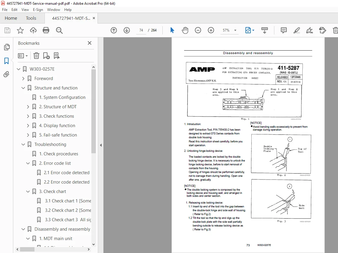
Tadano MDT-8 Multiplex Data Transmitter Crane Service Manual Repair PDF
Original price was: $95.00.$28.95Current price is: $28.95.
Complete Tadano factory service manual for MDT-8 Multiplex Data Transmitter system installed on TR and GR series mobile cranes. Covers comprehensive diagnostics, error codes, wiring diagrams, disassembly procedures, and troubleshooting for all compatible crane models including TR-450XL through TR-800XXL and GR-300EX through GR-700EXL series. Essential technical documentation for crane technicians servicing Tadano electronic control systems with I/O signal lists and connector pinouts.
Description
Tadano MDT-8 Multiplex Data Transmitter Crane Service Manual Repair PDF DOWNLOAD
DESCRIPTION
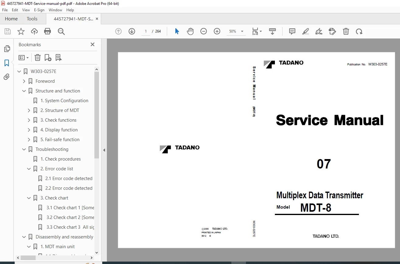
Tadano MDT-8 Multiplex Data Transmitter – Complete Factory Service Manual
This comprehensive Tadano MDT-8 service manual provides complete technical documentation for servicing, diagnosing, and repairing the Multiplex Data Transmitter (MDT) electronic control system installed on Tadano rough terrain and truck-mounted cranes. This professional-grade manual is the official Tadano factory documentation used by authorized service centers worldwide.
📋 FILE DETAILS
| Specification | Details |
|---|---|
| Manual Name | Tadano MDT-8 Multiplex Data Transmitter Service Manual |
| System Model | MDT-8 |
| Publication Number | W303-0257E |
| Publication Date | December 2006 (Updated March 2007) |
| Total Pages | 264 pages |
| PDF Quality | Excellent – Factory original documentation |
| File Format | PDF (A3 size, searchable) |
| File Size | 2.7 MB |
| Manufacturer | TADANO Ltd. |
🏗️ COMPATIBLE TADANO CRANE MODELS
This manual covers MDT-8 systems installed on the following Tadano crane models:
ROUGH TERRAIN CRANES (TR Series):
TR-450XL-4:
- Spec No. GR-450-1-00101
- Spec No. GR-450-1-00102
- Spec No. GR-450-1-00103
TR-500XL-4:
- Spec No. GR-500-1-00101
- Spec No. GR-500-1-00102
- Spec No. GR-500-1-00103
TR-500XL-4 (*):
- Spec No. GR-500-1-00211
- Spec No. GR-500-1-00213
- Spec No. GR-500-1-00214
TR-600XL-4:
- Spec No. GR-600-1-00101
TR-600XXL-4:
- Spec No. GR-600-1-00103
TR-600XXL-4 (*):
- Spec No. GR-600-1-00213
TR-800XXL-4:
- Spec No. GR-800-1-00101
TR-800XXL-4 (*):
- Spec No. GR-800-1-00211
TR-300XL-4:
- Spec No. TR-300-4-00101
- Spec No. TR-300-4-00102
TR-150XL-4:
- Spec No. TR-150-4-00101
- Spec No. TR-150-4-00102
TRUCK CRANES (GR Series):
GR-700EXL-1:
- Spec No. GR-700E-1-00101
- Spec No. GR-700E-1-00102
GR-700EXL-1 (*):
- Spec No. GR-700E-1-00211
- Spec No. GR-700E-1-00212
GR-550EX-1:
- Spec No. GR-550E-1-00211
- Spec No. GR-550E-1-00212
GR-300EX-1:
- Spec No. GR-300E-1-00201
- Spec No. GR-300E-1-00202
- Spec No. GR-300E-1-00203
📖 COMPLETE TABLE OF CONTENTS
SECTION 1: FOREWORD (Pages 1-6)
- Applicable Specification Numbers
- Complete crane model and spec number listing
- Model variation identification
- Manual Usage Guidelines
- Parts catalog reference procedures
- Service manual integration
- Product improvement notifications
SECTION 2: STRUCTURE AND FUNCTION (Pages 7-17)
- 2.1: System Configuration
- MDT system architecture
- Upper and lower unit integration
- Communication protocol overview
- 2.2: Structure of MDT
- Upper MDT construction and components
- Lower MDT construction and components
- Hardware specifications
- 2.3: Check Functions (10 Critical Safety Systems)
- System Runaway Prevention Circuit – Fail-safe control
- Memory Check Function – RAM integrity verification
- ROM Check Function – Program memory validation
- Transfer Data Check Function – Communication line monitoring
- Lower Unit Output Check Function – Output verification
- Power Supply Voltage Check Function – Electrical monitoring
- Manual Check Function – Operator-initiated diagnostics
- 2.4: Display Function
- Display LED indicators
- Software ID and version number display
- Error code display system
- Error history tracking
- Error history erasure procedures
- Check mode operation
- Priority of display functions
- AML (Advanced Machine Language) communication
- Port/bit number assignments
- Input/output signal number mapping
- 2.5: Fail-Safe Function
- Fail-safe state definitions
- Emergency shutdown protocols
SECTION 3: TROUBLESHOOTING (Pages 18-70)
- 3.1: Check Procedures (Pages 18-19)
- Systematic diagnostic approach
- Test equipment requirements
- Safety precautions during testing
- 3.2: Error Code List (Pages 20-66) Upper MDT Error Codes:
- Complete error code database (20+ codes)
- Error code descriptions
- Cause identification
- Diagnostic procedures
- Resolution steps
Lower MDT Error Codes:
- Lower unit specific error codes
- Output circuit fault codes
- Communication error codes
- Corrective action procedures
- 3.3: Check Charts (Pages 67-70)
- Check Chart 1 – Initial diagnostic flowchart
- Check Chart 2 – Component testing procedures
- Check Chart 3 – System verification flowchart
SECTION 4: DISASSEMBLY AND REASSEMBLY (Pages 71-83)
- 4.1: MDT Main Unit
- Complete disassembly procedures
- Component identification
- Reassembly instructions
- Torque specifications
- 4.2: Connector Service
- Removing and Attaching Connector Contacts:
- AMP.070 Multi-lock Connector (Mark A) – Step-by-step procedures
- AMP.040 Multi-lock Connector (Mark B) – Detailed instructions
- AMP.040 Multi-lock Connector (Mark C) – Assembly guidelines
- AMP.040 Multi-lock Connector (Mark D) – Pin removal/installation
- Crimping Receptacle Contact – Professional crimping techniques
- Removing and Attaching Connector Contacts:
SECTION 5: CONNECTION DIAGRAMS (Pages 84-125)
Model-Specific Wiring Diagrams:
5.1: TR-450XL-4 and TR-500XL-4
- Upper MDT connector diagrams
- Lower MDT connector diagrams
- Complete pin assignments
5.2: TR-500XL-4 (*)
- Upper MDT wiring schematics
- Lower MDT wiring schematics
- Signal path diagrams
5.3: TR-600XL-4, TR-600XXL-4, TR-800XXL-4, GR-700EXL-1
- Upper MDT complete connector pinouts
- Lower MDT complete connector pinouts
- Power and ground distribution
5.4: TR-600XXL-4 (), TR-800XXL-4 (), GR-700EXL-1 (*), GR-550EX-1
- Upper MDT electrical diagrams
- Lower MDT electrical diagrams
- Interface connections
5.5: TR-300XL-4 and GR-300EX-1
- Upper MDT connector schematics
- Lower MDT connector schematics
- Control signal routing
5.6: TR-150XL-4
- Upper MDT wiring diagrams
- Lower MDT wiring diagrams
- Complete electrical interface
SECTION 6: INPUT/OUTPUT SIGNAL LISTS (Pages 126-155)
Comprehensive I/O Signal Documentation for Each Model:
6.1: TR-450XL-4 and TR-500XL-4
- Upper I/O signal lists (complete port/bit assignments)
- Lower I/O signal lists (output specifications)
6.2: TR-500XL-4 (*)
- Upper I/O comprehensive mapping
- Lower I/O detailed specifications
6.3: TR-600XL-4, TR-600XXL-4, TR-800XXL-4, GR-700EXL-1
- Upper I/O signal reference tables
- Lower I/O signal reference tables
6.4: TR-600XXL-4 (), TR-800XXL-4 (), GR-700EXL-1 (*), GR-550EX-1
- Upper I/O complete listings
- Lower I/O complete listings
6.5: TR-300XL-4 and GR-300EX-1
- Upper I/O signal databases
- Lower I/O signal databases
6.6: TR-150XL-4
- Upper I/O comprehensive tables
- Lower I/O comprehensive tables
SECTION 7: DATA TABLES (Pages 156-264)
One-to-One Input/Output Systems:
- Model-specific I/O configurations
- Direct signal mapping
- Control logic documentation
Specific Function Documentation:
- Parking Lamp Control – All models
- Parking Alarm Systems – All models
- CHG Lamp Function – All models
- Headlamp Control – All models
- Rear Steering Lock – TR-150XL-4
- Rear Steering Lock Pin Lamp – TR-150XL-4
- Rear Steering Lock (Lower) – All models
- Rear Center Lamp – All models
- Outrigger Control Systems
- TR-450XL-4, TR-500XL-4 configurations
- TR-600XL through GR-550EX-1 configurations
- TR-300XL-4, GR-300EX-1, TR-150XL-4 configurations
- Outrigger Switch Neutral Position Detection
- Outrigger Retraction Operation Detection
- Exhaust Brake Control
- High/Low and 2WD/4WD Drive Mode Selector
- Engine Revolution Detection
And Many More Control Functions…
⚡ KEY TECHNICAL FEATURES COVERED
Multiplex Data Transmission:
- Upper MDT Unit – Cab-mounted control and display
- Lower MDT Unit – Chassis-mounted signal processing
- Digital Communication – Serial data transmission between units
- Multi-Function Integration – Single wire harness for multiple controls
Diagnostic Capabilities:
- Real-Time Error Monitoring – Continuous system health checks
- Error Code Display – LED-based fault indication
- Error History Storage – Fault logging for pattern analysis
- Check Mode Operation – Manual diagnostic mode access
- AML Integration – Advanced diagnostic communication
Safety Systems:
- Runaway Prevention – Automatic shutdown on system failure
- Fail-Safe Outputs – Safe state on communication loss
- Memory Integrity Checks – RAM and ROM verification
- Transfer Line Monitoring – Communication fault detection
- Power Supply Monitoring – Voltage anomaly detection
🎯 WHO NEEDS THIS MANUAL?
- Mobile Crane Technicians – Tadano crane specialists
- Heavy Equipment Service Centers – Crane repair facilities
- Construction Equipment Mechanics – Field service technicians
- Crane Rental Companies – Fleet maintenance departments
- Industrial Maintenance Teams – Manufacturing plant crane service
- Technical Training Centers – Heavy equipment training programs
- Tadano Authorized Dealers – Official service centers
- Independent Crane Service Providers – Third-party repair shops
💡 CRITICAL REPAIR INFORMATION INCLUDED
This Tadano crane service manual provides:
✓ Complete Error Code Database – Every MDT fault code with diagnostic procedures
✓ Wiring Diagrams for All Models – Model-specific connector pinouts
✓ I/O Signal Lists – Complete port/bit assignments for every crane model
✓ Connector Service Procedures – Pin removal/installation for 4 connector types
✓ Troubleshooting Flowcharts – Systematic fault diagnosis procedures
✓ Disassembly Instructions – Step-by-step MDT unit service
✓ Fail-Safe Function Documentation – Emergency shutdown protocols
✓ Check Mode Procedures – Manual diagnostic mode operation
✓ Function-Specific Diagrams – Outrigger, steering, brake control schematics
✓ Software Version Display – ID and version verification procedures
🔍 COMPREHENSIVE COVERAGE INCLUDES
System Architecture:
- Upper and lower MDT unit integration
- Communication protocol specifications
- Power distribution requirements
- Ground circuit design
Error Diagnostics:
- Upper MDT error codes (20+ codes documented)
- Lower MDT error codes (comprehensive listing)
- Error history retrieval procedures
- Error code clearing methods
- Check chart diagnostic flowcharts
Electrical Systems:
- Complete connector pin assignments
- Wire color coding (model-specific)
- Signal path tracing
- Power supply circuits
- Ground distribution
Control Functions:
- Outrigger control and sensing
- Steering lock systems
- Lighting control (parking, headlamp, center)
- Drive mode selection (2WD/4WD, High/Low)
- Exhaust brake control
- Engine revolution monitoring
🌟 MULTIPLEX SYSTEM EXPERTISE
Understanding MDT Technology: This manual covers Tadano’s advanced multiplex data transmission system, allowing you to:
- Service Digital Control Systems – Modern electronic crane controls
- Diagnose Communication Faults – Upper/lower unit data transmission
- Repair Complex Electrical Systems – Multi-function integrated wiring
- Perform System Verification – Complete functional testing
- Update and Configure – Software version management
Control Integration Covered:
- Outrigger Controls – Extend/retract sensing and interlocks
- Steering Systems – Lock mechanisms and position sensing
- Drive Controls – Transfer case and differential selection
- Lighting Systems – Integrated lamp control
- Safety Interlocks – Operational safety systems
📱 PERFECT FOR:
- Tadano Authorized Service Centers – Official repair documentation
- Independent Crane Service Companies – Professional technical reference
- Construction Equipment Dealerships – Sales and service support
- Crane Rental Fleets – In-house maintenance capabilities
- Industrial Facilities – Plant maintenance departments
- Mobile Crane Operators – Owner/operator maintenance
- Technical Training Schools – Heavy equipment programs
- Heavy Equipment Mechanics – Career development resource
⚠️ ESSENTIAL TECHNICAL INFORMATION
The manual includes critical specifications:
- AMP Multi-Lock Connectors – 4 different connector types with removal/installation
- Port/Bit Assignments – Complete I/O mapping for programming
- Error Code Definitions – Exact fault descriptions and causes
- Fail-Safe States – Safe shutdown conditions for each function
- Check Functions – 7 different safety monitoring systems
- Display Priorities – Error and status indication hierarchy
🔧 MODEL-SPECIFIC DOCUMENTATION
Each crane model series receives dedicated coverage:
- Connector Diagrams – Model-specific wiring schematics
- I/O Signal Lists – Unique port assignments per model
- Function Tables – Control logic specific to each series
- Specification Numbers – Exact version identification
This ensures you have the precise information needed for your specific crane model!
🌟 INSTANT DOWNLOAD – START SERVICING TODAY!
Don’t let MDT system failures shut down your crane operations! This genuine Tadano factory service manual gives you everything needed to professionally diagnose, repair, and maintain MDT-8 multiplex data transmitter systems. With 264 pages of detailed wiring diagrams, error codes, connector pinouts, and troubleshooting procedures covering 13 different crane models, you’ll have the confidence to tackle any electronic control system issue. Download now and become your company’s Tadano electronic systems expert!
Pricing Rationale:
- Comprehensive 264-page technical manual
- Covers 13 different crane models (TR and GR series)
- Complex electronic control system documentation
- Complete error code database with diagnostics
- Model-specific wiring diagrams and connector pinouts
- Essential for mobile crane service operations
- Tadano factory original documentation
- Specialized heavy equipment market
- Critical for crane fleet maintenance
- Limited availability of genuine Tadano service manuals
- High-value multiplex system troubleshooting information