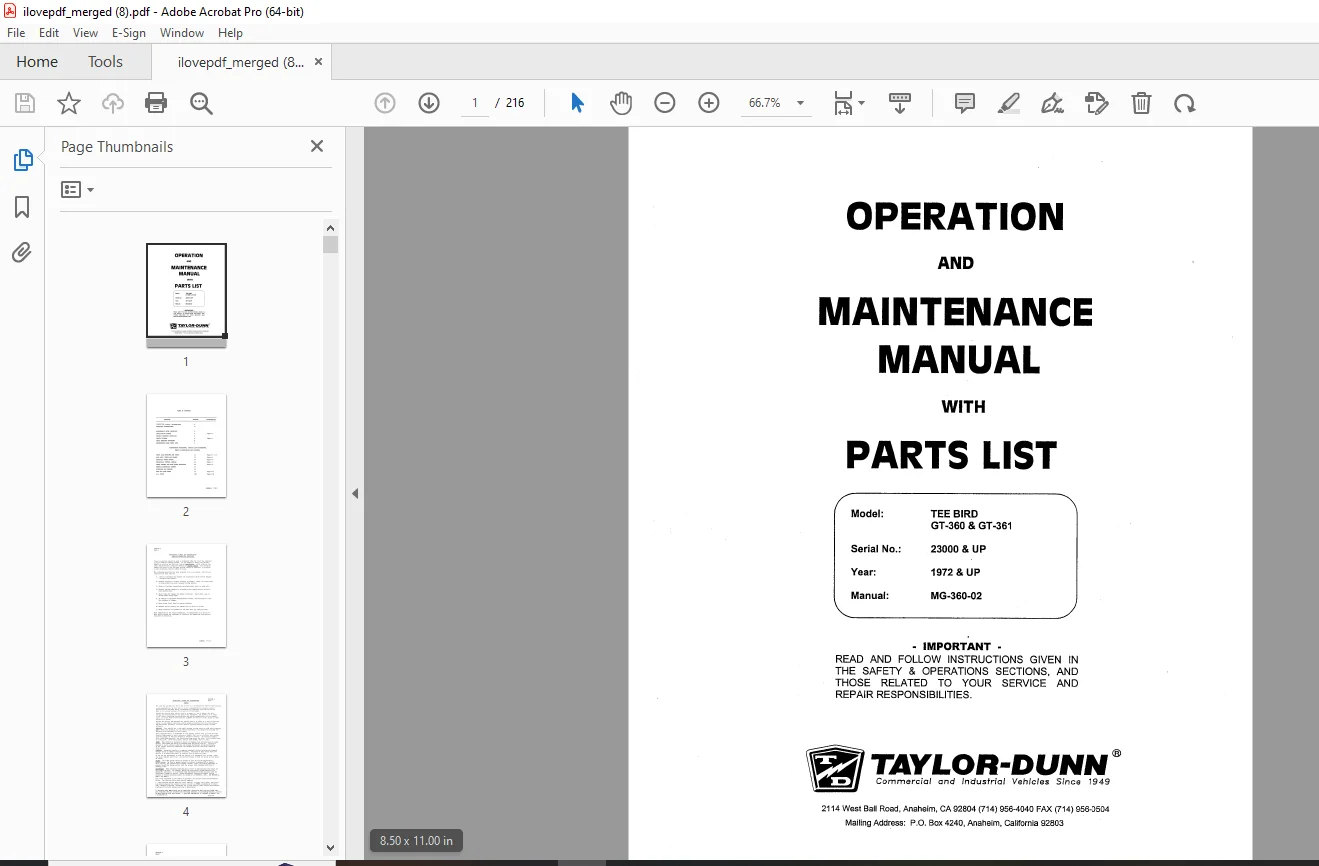
Taylor-Dunn GT-360 & GT-361 Operations & Maintenance With Parts Manual PDF
$28.95
Taylor-Dunn GT-360 & GT-361 Operations & Maintenance With Parts Manual S.NO 23000 & UP – PDF DOWNLOAD
Description
Taylor-Dunn GT-360 & GT-361 Operations & Maintenance With Parts Manual S.NO 23000 & UP – PDF DOWNLOAD
FILE DETAILS:
Taylor-Dunn GT-360 & GT-361 Operations & Maintenance With Parts Manual S.NO 23000 & UP – PDF DOWNLOAD
Language : English
Pages : 216
Downloadable : Yes
File Type : PDF
IMAGES PREVIEW OF THE MANUAL:
TABLE OF CONTENTS:
Taylor-Dunn GT-360 & GT-361 Operations & Maintenance With Parts Manual S.NO 23000 & UP – PDF DOWNLOAD
MG-360-02 Operation and Maintenance Manual with Part List 1
Table of Contents 2
Section A: Inspection, Safety, and Introduction 3
Section B: Operating Instructions 6
Section D: Maintenance Guide Checklist 9
Section E: Lubrication Diagram 12
Section F: Trouble Shooting Procedures 12
Section G: Wiring Diagram 15
Section H: Parts Ordering Procedure 16
Section I: Suggested Spare Parts List 17
Section J1: Front Axle, Steering and Tires – Maintenance Procedures 21
Section J2: “Power Traction” Rear Axle, Motor and Brakes – Maintenance Procedures 29
Section J2M: Electric Motors – Maintenance, Service and Adjustment 50
Section J4: Mechanical Control Linkage – Maintenance Procedures 55
Section J6: Master Control Switch – Maintenance Procedures 58
Section J7: General Electrical System – Maintenance Procedures 68
Section J8: Batteries – Maintenance Procedures 70
Section J9: Body and Trim – Maintenance Procedures 83
Maintenance Instructions and Parts Manual Supplement 89
Table of Contents 90
Section A: Inspection, Safety, and Introduction 91
Section B: Operating Instructions 94
Section C: 90 Day Warranty 97
Section E: Lubrication Diagram 98
Section G: Wiring Diagram 99
Section I: Suggested Spare Parts List100
Section J1: Front Axle, Steering, Tires and Suspension – Maintenance Procedures101
Section J1A: Steering Worm Assembly – Service and Adjustments106
Section J2: Brake System – Service and Adjustments109
Section J4: Mechanical Control Linkage – Maintenance Procedures112
Section J6: Master Control Switch – Maintenance, Service and Parts118
Section J9: Body and Trim – Maintenance Procedures120
Notice of Change122
MG-360-03 Operation and Maintenance Manual with Part List123
Important Information124
Table of Contents125
Section A: Inspection, Safety, and Introduction126
Section B: Operating Instructions129
Section D: Maintenance Guide Checklist132
Section E: Lubrication Diagram134
Section F: Trouble Shooting Procedures135
Section G: Wiring Diagram138
Section H: Parts Ordering Procedure140
Section I: Suggested Spare Parts List142
Section J1: Front Axle, Steering and Tires – Maintenance Procedures146
Section J2: “Power Traction” Rear Axle, Motor and Brakes – Maintenance Procedures154
Section J2M: Electric Motors – Maintenance, Service and Adjustment175
Section J4: Mechanical Control Linkage – Maintenance Procedures180
Section J6: Master Control Switch – Maintenance Procedures183
Section J7: General Electrical System – Maintenance Procedures193
Section J8: Batteries – Maintenance Procedures195
Section J9: Body and Trim – Maintenance Procedures208
Notice of Change216
DESCRIPTION:
Taylor-Dunn GT-360 & GT-361 Operations & Maintenance With Parts Manual S.NO 23000 & UP – PDF DOWNLOAD
- OPERATING INSTRUCTIONS :
- controls on your Taylor-Dunn vehicle have been designed and located for convenience of operation and efficient performance. Before driving your vehicle for the first time, familiarize yourself with each of the controls. Read the following instructions and with power .Qf!., operate each control.
- STEERING ‘llle steering system is of the automotive type. Turn the steering wheel to the right (or clockwise) for a right turn and left (or counterclockwise) for a left turn.
- KEY LOCK Your vehicle is equipped with a keyed lock located on the corner of the forward/ reverse switch. It is designed to lock the switch in the neutral position only. 1he key will remove from the lock in the locked position (neutral) only.
- PARKING BRAKE ‘llle hand operated parking brake is located near the center of the floor board. It is much easier to apply or release when the service brake foot pedal is depressed firmly. To engage parking brake, grasp the handle and pull rearward as far as possible. To release, push handle all the way forward. Avoid putting the vehicle in motion while the parking brake is applied.
- SERVICE BRAKE ‘llle brake pedal is designed and located for right foot operation. It is the pedal located to the left of the accelerator pedal. It functions the same as the brake pedal in yo~utomobile. Depressing the pedal applies the braking action. 1he greater the effort applied to the pedal with your foot, the greater the braking action to your vehicle. Removing your foot from the pedal allows immediate release of the braking action.
- FORWARD-REVERSE SWTICH 1he forward-reverse switch is located to the right of, and below, the drivers seat, and can be operated only when the key is in the unlocked position. To place the handle in the Forward position, move it downward. To place the handle in the Reverse position, move it upward.
- CAUTION: 1he forward-reverse switch serves the same purpose as the transmission in your automobile. Treat it with the same respect and care. 00 NOT SHIFT from forward to reverse or vice-versa while the vehicle is in motion. Shifting while in motion, especially near top speed, causes great strain to your entire vehicle and will eventually cause severe damage.
G.B 24/01/25