Taylor-Dunn R 3-80 Operators Routine Maintenance Parts Manual S.NO. 78167-81203 PDF
$13.95
Taylor-Dunn R 3-80 Operators Routine Maintenance Parts Manual S.NO. 78167-81203 – PDF DOWNLOAD
Description
Taylor-Dunn R 3-80 Operators Routine Maintenance Parts Manual S.NO. 78167-81203 – PDF DOWNLOAD
FILE DETAILS:
Taylor-Dunn R 3-80 Operators Routine Maintenance Parts Manual S.NO. 78167-81203 – PDF DOWNLOAD
Language : English
Pages : 39
Downloadable : Yes
File Type : PDF
IMAGES PREVIEW OF THE MANUAL:
TABLE OF CONTENTS:
Taylor-Dunn R 3-80 Operators Routine Maintenance Parts Manual S.NO. 78167-81203 – PDF DOWNLOAD
MD-175-01 Operation and Maintenance Manual with Part List 1
Important Information 2
Table of Contents 3
Section 1: Inspection, Safety and Introduction 4
Section 2: Taylor-Dunn Limited 90 Warranty 7
Section 3: Operating Instructions 8
Section 4: Maintenance Guide Checklist15
Section 5: Lubrication Diagram16
Section 6: Wiring Diagram17
Section 7: Batteries, Inspection18
Section 8: Operation of “Lester Matic” Battery Chargers19
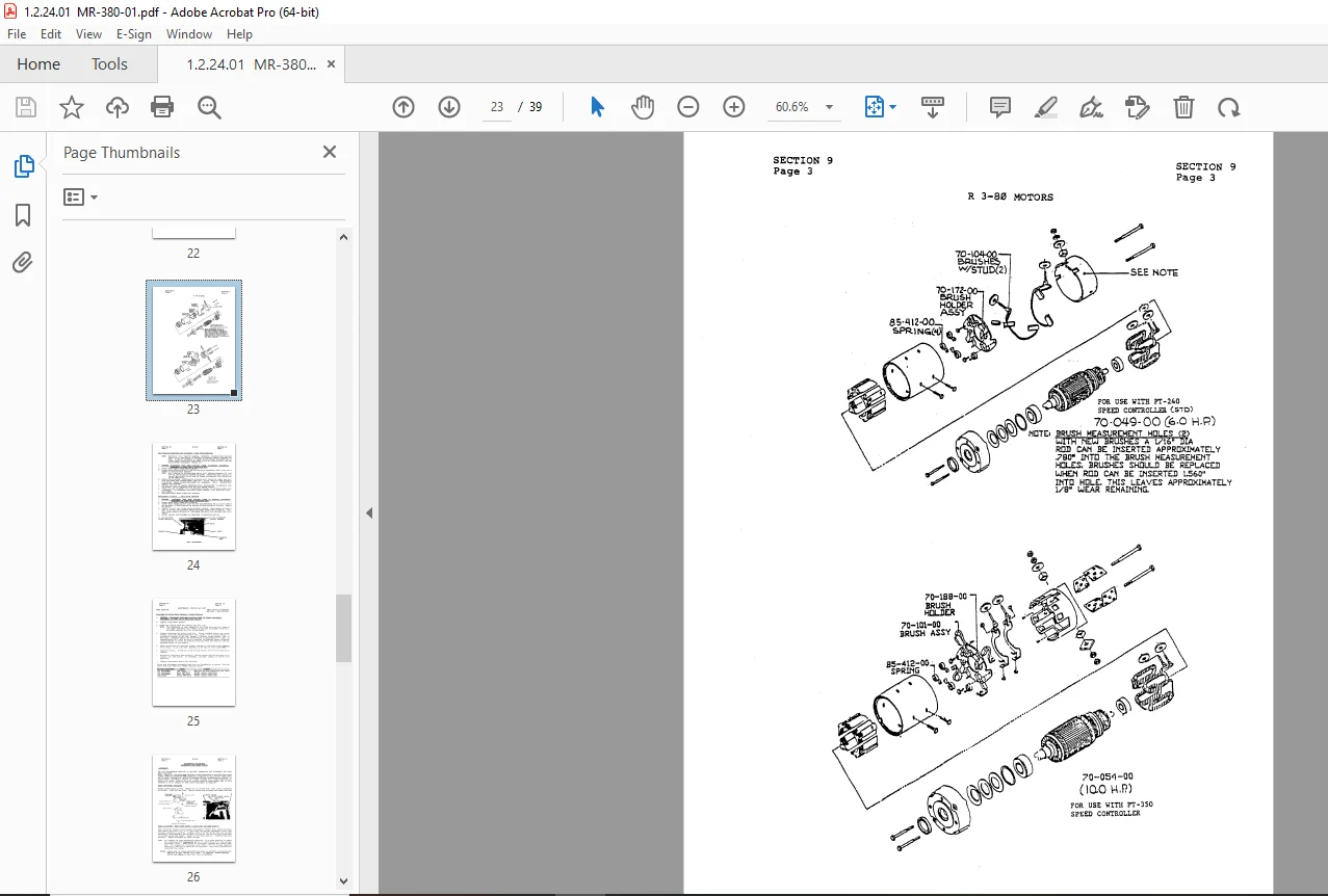
Section 9: Motor Maintenance21
Section 10: Belt Drive – Maintenance Procedures24
Section 11: Brake – Maintenance Procedure26
Section 12: PWR-TRON 240, 350 and 480 Introduction29
Section 13: Trouble Shooting Procedures32
Section 14: Options and Kits33
Section 15: Parts Ordering Procedure35
M8-001-00 Rheostat Installed Vehicles Supplement Owners Manual36
DESCRIPTION:
Taylor-Dunn R 3-80 Operators Routine Maintenance Parts Manual S.NO. 78167-81203 – PDF DOWNLOAD
OPERATING INSTRUCTIONS:
the controls on your Taylor-Dunn vehicle have been designed and located for convenience of operation and efficient performance. Before driving your vehicle for the first time, familiarize yourself with each of the controls. Read the following instructions and with power OFF, operate each control.
- STEERING The steering wheel and steering system is similar to automotive types. Turn the steering wheel to the right {clockwise) for a right turn and left (counterclockwise) for a left turn.
- KEY LOCK Your vehicle is equipped with a keyed lock located on the instrument panel. It is designed to lock the switch in the neutral position only. The key will remove from the lock in the locked position (neutral) only.
- AUTOMATIC DEADMAN SEAT SWITCH This system is standard on your vehicle and acts as a safety feature when operator arises from seat. Seat will rise and disconnect battery/motor circuit.
- SERVICE BRAKE (FOOT) The brake pedal is designed and located for right foot operation. It is the pedal located to the left of the accelerator pedal. It functions the same as the brake pedal in yourautomobile. Removing your foot from the pedal allows immediate release of the braking action to your vehicle.
- PARK BRAKE This is a hand brake located next to the driver’s seat. Take firm grip with right hand, depressing handle button and pull up. Release by depressing button and push down.
- FORWARD/REVERSE SWITCH The forward/reverse switch is located on the instrument panel. It is a rocker type switch. Depressing the upper part places the vehicle in forward. Depressing the lower portion full downward places vehicle in reverse. Center position is off.
- CAUTION: The forward/reverse switch serves the same purpose as the transmission SELECTOR in your automobile. Treat it with the same respect and care. 00 NOT SHIFT from forward to reverse or vice-versa while the vehicle is in motion.
- ACCELERATOR SWITCH The accelerator pedal is located to the right of the brake pedal. It is designed for right foot operation similar to your automobile. Depressing the pedal turns the power on to the motor.· It also controls the amount of power delivered to the motor. When driving your vehicle you will be able to feel full power when accelerator is fully depressed and minimum power when only partially depressed. You will have the same control of power in both directions of travel. Your forward/reverse switch determines the direction of travel and your accelerator pedal controls the speed.
- HORN BUTTON The horn button is located on the floor board to the left of the steering column. Depressing button sounds horn. Releasing button will immediately silence horn. CHARGE INDICATOR: Located on instrument panel. Shows condition of batteries at all times.
G.B 25/01/25