Taylor-Dunn SC 1-59,AN 1-70 AN 1-71 Operation & Maintenance Parts Manual PDF
$31.95
Taylor-Dunn SC 1-59,AN 1-70 AN 1-71 Operation & Maintenance Parts Manual S.NO.22800-78166 – PDF DOWNLOAD
Description
Taylor-Dunn SC 1-59,AN 1-70 AN 1-71 Operation & Maintenance Parts Manual S.NO.22800-78166 – PDF DOWNLOAD
FILE DETAILS:
Taylor-Dunn SC 1-59,AN 1-70 AN 1-71 Operation & Maintenance Parts Manual S.NO.22800-78166 – PDF DOWNLOAD
Language : English
Pages : 617
Downloadable : Yes
File Type : PDF
IMAGES PREVIEW OF THE MANUAL:
TABLE OF CONTENTS:
Taylor-Dunn SC 1-59,AN 1-70 AN 1-71 Operation & Maintenance Parts Manual S.NO.22800-78166 – PDF DOWNLOAD
MA-159-00 Operation and Maintenance Manual with Part List 1
Important Information 2
Table of Contents 3
Section A: Inspection, Safety, and Introduction 4
Section B: Operating Instructions 7
Section D: Maintenance Guide Checklist 14
Section E: Lubrication Diagram 16
Section F: Trouble Shooting Procedures 17
Section G: Wiring Diagram 19
Section H: Parts Ordering Procedure 20
Section I: Suggested Spare Parts List 21
Section J1: Front Axle, Fork, Steering and Tires – Maintenance Procedures 23
Section J2: “Power Traction” Rear Axle, Motor and Brakes – Maintenance Procedures 31
Section J2M: Electric Motors – Maintenance, Service and Adjustment 46
Section J4: Mechanical Control Linkage – Maintenance Procedures 51
Section J5: Forward/Reverse Control Switch – Maintenance Procedures 55
Section J6: Rheostat Speed Control – Maintenance Procedures 60
Section J7: General Electrical System – Maintenance Procedures 65
Section J8: Batteries – Maintenance Procedures 67
Section J9: Body and Trim – Maintenance Procedure 90
Notice of Change 94
MA-159-01 Operation and Maintenance Manual with Part List 95
Important Information 96
Table of Contents 97
Section A: Inspection, Safety, and Introduction 98
Section B: Operating Instructions101
Section D: Maintenance Guide Checklist103
Section E: Lubrication Diagram105
Section F: Trouble Shooting Procedures106
Section G: Wiring Diagram108
Section H: Parts Ordering Procedure109
Section I: Suggested Spare Parts List110
Section J1: Front Axle, Fork, Steering and Tires – Maintenance Procedures112
Section J2: “Power Traction” Rear Axle, Motor and Brakes – Maintenance Procedures119
Section J2M: Electric Motors – Maintenance, Service and Adjustment133
Section J4: Mechanical Control Linkage – Maintenance Procedures139
Section J5: Forward/Reverse Control Switch – Maintenance Procedures143
Section J6: Rheostat Speed Control – Maintenance Procedures148
Section J7: General Electrical System – Maintenance Procedures153
Section J8: Batteries – Maintenance Procedures155
Section J9: Body and Trim – Maintenance Procedure171
PWR-TRON – Table of Contents174
PWR-TRON – Introduction175
Notice of Change200
MA-159-02 Operation and Maintenance Manual with Part List201
Important Information202
Table of Contents203
Section A: Inspection, Safety, and Introduction204
Section B: Operating Instructions207
Section D: Maintenance Guide Checklist213
Section E: Lubrication Diagram215
Section F: Trouble Shooting Procedures216
Section G: Wiring Diagram218
Section H: Parts Ordering Procedure219
Section I: Suggested Spare Parts List220
Section J1: Front Axle, Fork, Steering and Tires – Maintenance Procedures222
Section J2: “Power Traction” Rear Axle, Motor and Brakes – Maintenance Procedures229
Section J2M: Electric Motors – Maintenance, Service and Adjustment242
Section J4: Mechanical Control Linkage – Maintenance Procedures248
Section J5: Forward/Reverse Control Switch – Maintenance Procedures252
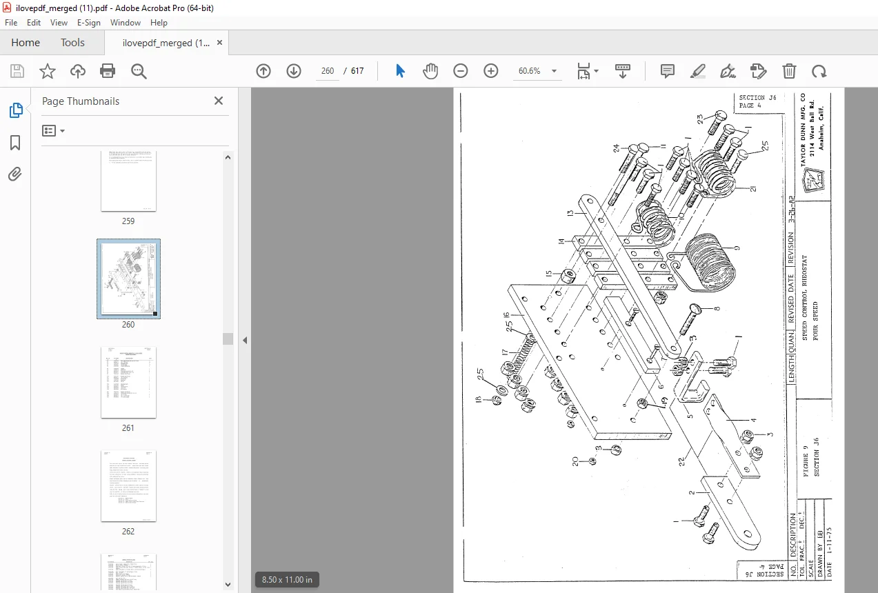
Section J6: Rheostat Speed Control – Maintenance Procedures257
Section J7: Body and Trim – Maintenance Procedure262
Section J8: Important Facts on Battery Chargers264
Section J9: Body and Trim – Maintenance Procedure282
PWR-TRON – Table of Contents285
PWR-TRON – Introduction286
Notice of Change314
Section 20: Body and Trim – Maintenance Procedures407
Section 19: Parts Ordering Procedure406
Section 18: Suggested Spare Parts List404
Section 17: General Electrical System – Maintenance Procedures403
Section 16: Rheostat Speed Control – Maintenance Procedures399
Section 15: PWR-TRON II – Introduction382
Section 14: Forward/Reverse Switch – Maintenance Procedures378
Section 13: Mechanical Control Linkage – Maintenance Procedures375
Section 12: Electric Motors – Maintenance, Service and Adjustment371
Section 11: “Power Traction” Rear Axle, Motor and Brakes – Maintenance Procedures359
Section 10: Front Axle, Fork, Steering and Tires – Maintenance Procedures353
Section 9: Charger – Maintenance, Service and Adjustment340
Section 8: Important Facts on Batteries and Chargers334
Section 7: Wiring Diagram333
Section 6: Trouble Shooting Procedures331
Section 5: Lubrication Diagram330
Section 4: Maintenance Guide Checklist328
Section 3: Operating Instructions322
Section 2: Taylor-Dunn Limited 90 Warranty321
Section 1: Inspection, Safety and Introduction318
Table of Contents317
Important Information316
MA-159-03 Operation and Maintenance Manual with Part List315
MA-159-04 Operation and Maintenance Manual with Part List410
Important Information411
Table of Contents412
Section 1: Inspection, Safety and Introduction413
Section 2: Taylor-Dunn Limited 90 Warranty416
Section 3: Operating Instructions417
Section 4: Maintenance Guide Checklist423
Section 5: Lubrication Diagram425
Section 6: Trouble Shooting Procedures426
Section 7: Wiring Diagram428
Section 8: Important Facts on Batteries and Chargers429
Section 9: Charger – Maintenance, Service and Adjustment435
Section 10: Front Axle, Fork, Steering and Tires – Maintenance Procedures445
Section 11: “Power Traction” Rear Axle, Motor and Brakes – Maintenance Procedures451
Section 12: Electric Motors – Maintenance, Service and Adjustment463
Section 13: Mechanical Control Linkage – Maintenance Procedures467
Section 14: Forward/Reverse Switch – Maintenance Procedures470
Section 15: PWR-TRON II – Introduction474
Section 16: Rheostat Speed Control – Maintenance Procedures491
Section 17: General Electrical System – Maintenance Procedures495
Section 18: Suggested Spare Parts List496
Section 19: Parts Ordering Procedure498
Section 20: Body and Trim – Maintenance Procedures499
MA-159-05 Operation and Maintenance Manual with Part List502
Table of Contents504
Section 1: Introduction506
Section 2: Operating Guidelines514
Section 3: Scheduled Maintenance and Service Procedures520
Section 4: Illustrated Parts List 566
Manual Revisions616
Notes617
DESCRIPTION:
Taylor-Dunn SC 1-59,AN 1-70 AN 1-71 Operation & Maintenance Parts Manual S.NO.22800-78166 – PDF DOWNLOAD
- The controls on your Taylor-Dunn vehicle have been designed and located for convenience of operation and efficient performance. Before driving your vehicle for the first time, familiarize yourself with each of the controls. Read the following instructions and with power .QIT., operate each control.
- The steering wheel and steering system are similar to automotive types. Turn the steering wheel to the right (or clockwise) for a right turn and left (or counterclockwise) for a left turn.
- To turn right, move the tiller to the right, and to tμrn left, move the tiller to the left. KEY LOCK Your vehicle is equipped with a keyed lock located on the corner of forward reverse switch. It is designed to lock. the switch in the neutral position only. The key will remove from the lock in the locked position (Neutral) only.
- The foot treadle is a combination brake and accelerator control. It is pivoted near the center so that application of heel pressure to the rear of the treadle applies braking action, while application of toe pressure to the front of the treadle releases the brakes and controls the amount of power delivered to the motor.
- Full power is achieved when the front of the treadle is depressed as far as it is allowed to travel, and minimum power is achieved when the front of the treadle is partially depressed. Intermediate speeds occur between those two P.OSitions. Spring pressure holds the treadle in the braked position when no foot pressure is applied. ‘lllis provides automatic braking when the vehicle is parked and left unattended.
- The forward-reverse switch is located on the console, to the right of the driver. To travel forward, move the o~erating handle to the position marked “FORWARD”. To travel rearward, move the operating handle to the position marked “
- forward-reverse switch serves the same purpose as the transmission in your automobile. Treat it with the same respect and care. 00 NOT SHIFT from forward to reverse or viceversa while the vehicle is in motion. Shifting while in motion, especially near top speed, causes great strain to your entire vehicle and will eventually cause severe damage
G.B 25/01/25