Taylor-Dunn SS5-34 Operation & Maintenance Parts Manual S.No.31000 to 77776 PDF
$33.95
Taylor-Dunn SS5-34 Operation & Maintenance Parts Manual S.No.31000 to 77776 – PDF DOWNLOAD
Description
Taylor-Dunn SS5-34 Operation & Maintenance Parts Manual S.No.31000 to 77776 – PDF DOWNLOAD
FILE DETAILS:
Taylor-Dunn SS5-34 Operation & Maintenance Parts Manual S.No.31000 to 77776 – PDF DOWNLOAD
Language : English
Pages : 853
Downloadable : Yes
File Type : PDF
IMAGES PREVIEW OF THE MANUAL:
TABLE OF CONTENTS:
Taylor-Dunn SS5-34 Operation & Maintenance Parts Manual S.No.31000 to 77776 – PDF DOWNLOAD
MS-534-01 Operation and Maintenance Manual with Parts List 1
Important Information 3
Table of Contents 4
Section A: Inspection, Safety, and Introduction 5
Section B: Operating Instructions 8
Section D: Maintenance Guide Checklist 15
Section E: Lubrication Diagram 16
Section F: Trouble Shooting Procedures 17
Section G: Wiring Diagram 19
Section H: Parts Ordering Procedure 21
Section I: Suggested Spare Parts List 22
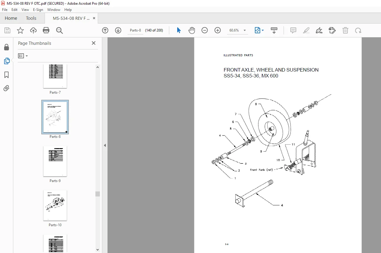
Section J1: Front Axle, Fork, Steering and Tires – Maintenance Procedures 24
Section J2: Belt Drive Rear Axle, Motor and Brakes 33
Section J2B: Brakes – Service and Adjustment 36
Section J2D: Drive Belts, Pulleys & Motor Mounts – Maintenance, Service and Adjustment 39
Section J2H: Rear Axle and Housing – Maintenance, Service and Adjustment 44
Section J2M: Electric Motors – Maintenance, Service and Adjustment 47
Section J2R: Differential Assembly – Service and Adjustment 54
Section J4: Mechanical Control Linkage – Maintenance Procedures 60
Section J5: Forward/Reverse Control Switch – Maintenance Procedures 63
Section J6: Master Control Switch – Maintenance, Service and Parts 65
Section J7: General Electrical System – Maintenance Procedures 73
Section J8: Batteries – Maintenance Procedures 75
Section J9: Body and Trim – Maintenance Procedures 87
Notice of Change 91
MS-534-02 Operation and Maintenance Manual with Part List 92
Important Information 93
Table of Contents 94
Section A: Inspection, Safety, and Introduction 95
Section B: Operating Instructions 99
Section D: Maintenance Guide Checklist107
Section E: Lubrication Diagram109
Section F: Trouble Shooting Procedures110
Section G: Wiring Diagram112
Section H: Parts Ordering Procedure114
Section I: Suggested Spare Parts List115
Section J1: Front Axle, Fork, Steering and Tires – Maintenance Procedures117
Section J2: Belt Drive Rear Axle, Motor and Brakes – Maintenance Procedures126
Section J2B: Mechanical Disk Brake System – Maintenance Procedures127
Section J2D: Drive Belts, Pulleys & Motor Mounts – Service and Adjustments131
Section J2H:Rear Axle and Housing – Maintenance, Service and Adjustments137
Section J2M: Electric Motors – Maintenance, Service and Adjustment140
Section J2R: Differential Assembly – Service and Adjustment149
Section J4: Mechanical Control Linkage – Maintenance Procedures155
Section J6: Master Control Switch – Maintenance Procedures158
Section J7: General Electrical System – Maintenance Procedures165
Section J8: Batteries – Maintenance Procedures168
Section J9: Body and Trim – Maintenance Procedure182
PWR-TRON II – Table of Contents186
PWR-TRON II – Introduction187
Notice of Change212
MS-534-03 Operation and Maintenance Manual with Part List213
Important Information214
Table of Contents215
Section 1: Inspection, Safety and Introduction216
Section 2: Taylor-Dunn Limited 90 Warranty219
Section 3: Operating Instructions220
Section 4: Maintenance Guide Checklist226
Section 5: Lubrication Diagram228
Section 6: Trouble Shooting Procedures229
Section 7: Batteries – Maintenance Procedures231
Section 8: Charger – Maintenance, Service and Adjustment236
Section 9: Wiring Diagram245
Section 10: Front Axle, Fork, Steering and Tires – Maintenance Procedures246
Section 11: Belt Drive Rear Axle, Motor and Brakes – Maintenance Procedures255
Section 12: Mechanical Control Linkage – Maintenance Procedures273
Section 13: Electric Motors – Maintenance, Service and Adjustment275
Section 14: Master Control Switch – Maintenance Procedures284
Section 15: PWR-TRON 240290
Section 16: Electrical System Components – Maintenance Procedures305
Section 17: Suggested Spare Parts List307
Section 18: Parts Ordering Procedure309
Section 19: Body and Trim – Maintenance Procedures310
Notice of Change314
MS-534-04 Operation and Maintenance Manual with Part List315
Important Information316
Table of Contents317
Section 1: Inspection, Safety, and Introduction318
Section 2: Taylor-Dunn Limited 90 Warranty321
Section 3: Operating Instructions322
Section 4: Maintenance Guide Checklist328
Section 5: Lubrication Diagram330
Section 6: Trouble Shooting Procedures331
Section 7: Battery – Maintenance Procedures333
Section 8: Charger – Maintenance, Service and Adjustment338
Section 9: Wiring Diagram347
Section 10: Front Axle, Fork, Steering and Tires – Maintenance Procedures348
Section 11: Belt Drive Rear Axle, Motor and Brakes – Maintenance Procedures357
Section 12: Mechanical Control Linkage – Maintenance Procedures375
Section 13: Electric Motors – Maintenance, Service and Adjustment379
Section 14: Master Control Switch – Maintenance Procedures388
Section 15: PWR-TRON II – Introduction395
Section 16: Electric System Components – Maintenance Procedures412
Section 17: Suggested Spare Parts List414
Section 18: Parts Ordering Procedure416
Section 19: Body and Trim – Maintenance Procedures417
Notice of Change421
MS-534-05 Operation and Maintenance Manual with Part List422
Section 1: Inspection, Safety and Introduction427
Section 2: Taylor-Dunn Limited 90 Warranty430
Section 4: Maintenance Guide Checklist437
Section 5: Lubrication Diagram439
Section 6: Trouble Shooting Procedures440
Section 7: Batteries – Maintenance Procedures442
Section 8: Charger – Maintenance, Service and Adjustment447
Section 9: Wiring Diagram457
Section 10: Front Axle, Fork, Steering and Tires – Maintenance Procedures458
Section 11: Belt Drive Rear Axle, Motor and Brakes – Maintenance Procedures467
Section 12: Mechanical Control Linkage – Maintenance Procedures485
Section 13: Electric Motors – Maintenance, Service and Adjustment489
Section 14: Master Control Switch – Maintenance Procedures492
Section 15: PWR-TRON Model SS – Introduction499
Section 16: Electrical System Components – Maintenance Procedures516
Section 17: Suggested Spare Parts List518
Section 18: Parts Ordering Procedure520
Section 19: Body and Trim – Maintenance Procedures521
Notice of Change525
MS-534-06 Operation and Maintenance Manual with Part List526
Table of Contents527
Section 1: Inspection, Safety and Introduction528
Section 3: Operating Instructions531
Section 4: Maintenance Guide Checklist537
Section 5: Lubrication Diagram539
Section 6: Trouble Shooting Procedures540
Section 7: Batteries – Maintenance Procedures542
Section 8: Charger – Maintenance, Service and Adjustment547
Section 9: Wiring Diagram557
Section 10: Front Axle, Fork, Steering and Tires – Maintenance Procedures558
Section 11: Belt Drive Rear Axle, Motor and Brakes – Maintenance Procedures567
Section 12: Mechanical Control Linkage – Maintenance Procedures585
Section 13: Electric Motors – Maintenance, Service and Adjustment589
Section 14: Master Control Switch – Maintenance Procedures591
Section 15: PWR-TRON Model SS – Introduction598
Section 16: Electrical System Components – Maintenance Procedures615
Section 17: Suggested Spare Parts List617
Section 18: Parts Ordering Procedure619
Section 19: Body and Trim – Maintenance Procedures620
Notice of Change624
MS-001-00 Assembly and Installation Supplement625
MS-534-08 Operation and Maintenance Manual with Parts List631
Operator and Maintenance Manual633
Table of Contents634
Section 1: Vehicle Description and Specifications644
Section 1:Safety Rules and Operational Information652
Section 2: Maintenance and Service Procedures662
Section 3: Electrical and Charger Troubleshooting
736
Section 4: Illustrated Part List790
Appendix848
DESCRIPTION:
Taylor-Dunn SS5-34 Operation & Maintenance Parts Manual S.No.31000 to 77776 – PDF DOWNLOAD
- The controls on your Taylor-Dunn vehicle have been designed and located for convenience of operation and efficient performance. Before driving your vehicle for the first time, familiarize yourself with each of the controls after carefully reading ~he instructions contained in this manual. _
- The Steering Tiller is designed for two hand control. It is directly connected to the– front wheel fork spindle. Move the tiller counterclockwise when making a left turn or clockwise when making a right turn.
- The Steering Wheel and Steering System is similar to automotive types. Turn the steering wheel to the right (or clockwise) for a right run and left (or counterclockwise) for a left turn.
- Your vehicle is equipped with a keyed lock located on the corner of forward/ reverse switch. It is designed to lock the switch in the Neutral position only. The key will remove from the lock in the locked position (Neutral) only.
- The brake pedal is designed and located for right foot operation. It is the pedal located to the left of accelerator pedal. It functions the same as the brake pedal in your automobile. Depressing the pedal applies the braking action. The greater the effort applied to the pedal with your foot, the greater the braking action to your vehicle. Removing your foot from the pedal allows immediate release of the braking action to your vehicle.
- The brake pedal pad swivels to engage a lock for parking vehicle. Applying pressure to the rear of the pedal with your heel will engage the lock and hold brake in the on position after foot is remove from pedal. To release brake from the locked position apply foot pressure to the forward part of the pedal. Lock will disengage and pedal will be free to travel.
- The forward/reverse switch handle is located to the right of the drivers seat. To place in forward position push handle downward. To place in reverse position pull the handle upward.
- The forward/reverse switch serves the same purpose as the transmission in your automobile. Treat it with the same respect and care. DO NOT SHIFT from forward to reverse or vice-versa while the vehicle is in motion. Shifting while in motion, especially near top speed, causes great strain to your entire vehicle and will eventually cause severe damage.
G.B 25/01/25