TCM Tractor Shovel STD10 Parts Manual 611A – PDF DOWNLOAD
Original price was: $67.00.$26.95Current price is: $26.95.
TCM Tractor Shovel STD10 Parts Manual 611A – PDF DOWNLOAD
Description
TCM Tractor Shovel STD10 Parts Manual 611A – PDF DOWNLOAD
FILE DETAILS:
TCM Tractor Shovel STD10 Parts Manual 611A – PDF DOWNLOAD
Language : English
Pages :220
Downloadable : Yes
File Type : PDF
Size:6.58 MB
DESCRIPTION
TCM Tractor Shovel STD10 Parts Manual 611A – PDF DOWNLOAD
How to Use this Part List
This part list covers all standard and optional replacement parts for the TCM Tractor Shovel Model Tor-STD10 (Diesel Engine).
- This part list is organized in 8 groups (see contents) according to the function of the vehicle.
- Instruction to the item numbers: Example: (I) A capital letter instead of item No. represents an assembled part (organized over two parts). (2) Using hyphens instead of item No. represents two types of parts coming after item No.3 such as parts. (3) Using a small letter with item No. in remarked column such as (item 8a) represents an assembled part or parts which included more than two parts.
- Descriptions in each part list represent names, proper places, and function of parts. Also, you will see (inc.1 thru 7) in remarked column, the rightest column which represents an assembly included item No. 1 thru 7. (Be sure to follow the above instructions when you order parts).
- Quantity always represents one vehicle unless there is a special note.
- Key to the symbols: ASSY – Assembly STD – Standard AR – As Required R.H – Right Hand L.H – Left Hand O – Not Illustrated NS – Not Sold Separately
- Using right hand and left hand in this part list, it is viewed from the operator’s seat facing forward.
- When ordering spare parts, please be sure to notice model no., chassis no., part no., part name, and quantity. Whenever replacing the TCM vehicle parts, be sure to use genuine TCM parts. Otherwise, it may cause trouble or serious accidents.
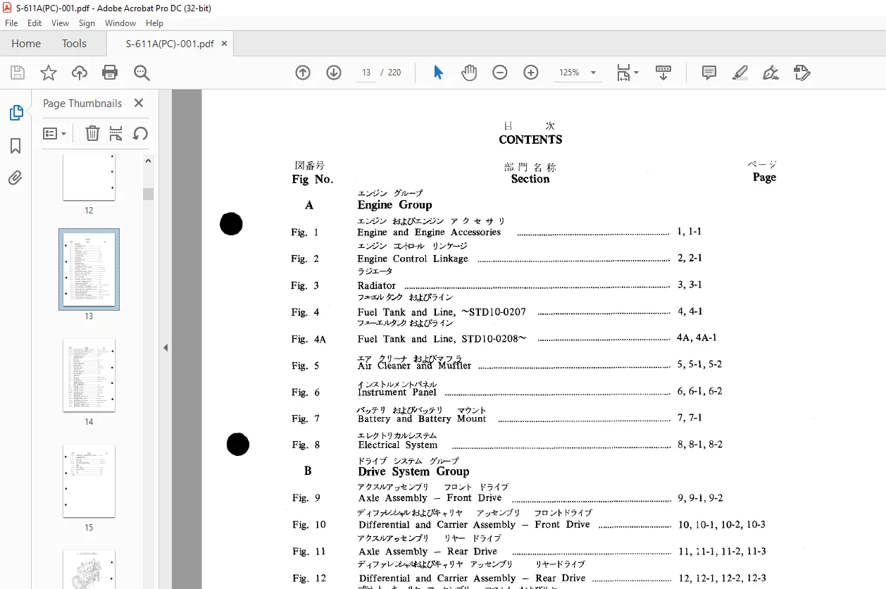
TABLE OF CONTENTS:
TCM Tractor Shovel STD10 Parts Manual 611A – PDF DOWNLOAD
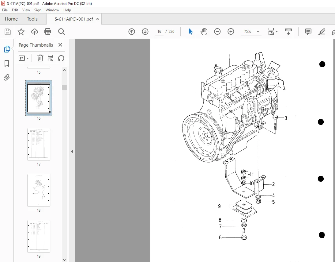
Engine and Engine Accessories
Fig.2 Engine Control Linkage
Fig.3 Radiator
Fig.4 Fuel Tank and Line, STD10-0207
Fig.4A Fuel Tank and Line, STD10-0208~
Fig.5 Demand Good Stewardship
Fig.6 Instrument Panel
Fig.7 Battery and Battery Mount
Fig.8 Electrical System
B Drive System Group
Fig.9 Axle Assembly – Front Drive 9, 9-1, 9-2, 10, 10-1, 10-2, 10-3, 11, 11-1, 11-2, 11-3, 12, 12-1, 12-2, 12-3
Fig.10 Differential and Carrier Assembly – Front Drive
Fig.11 Axle Assembly – Rear Drive
Fig.12 Differential and Carrier Assembly – Rear Drive
Fig.13 Planet Carrier Assembly – Front and Rear 13, 13-1
Fig.14 Brake Assembly – Front and Rear 14, 14-1, 14-2, 15, 15-1
Fig.15 Wheel – Front and Rear
Fig.16 Propeller Shaft – Transmission to Front Axle 16, 16-1
Fig.17 Propeller Shaft – Transmission to Rear Axle 17, 17-1
Fig.18 Transmission Mounting and Dipstick 18, 18-1, 19, 19-1, 19-2, 19-3, 19-4, 19-5
Fig.19 Drive Unit (Transmission Group) – STD10-0012
Fig.19-1 Drive Unit (Clutch Group – Forward and Low) – STD10-0012 19-1, 19-1-1
Fig.19-2 Drive Unit (Clutch Group – Reverse and High) – STD10-0012 19-2, 19-2-1
Fig.19-3 Drive Unit (Torque Converter Group)
Fig.19-4 Drive Unit (Parking Brake Group) 19-3, 19-3-1, 19-3-2, 19-3-3, 19-4, 19-4-1, 19A, 19A-1, 19A-2, 19A-3, 19A-4
Fig.19A-1 Drive Unit (Clutch Group – Forward and Low) – STD10-0013 19A-1, 19A-1-1
Fig.19A-2 Drive Unit (Clutch Group – Reverse and High) – STD10
Fig. 19A-3 Drive Unit (Control Valve-Transmission) STD10-0013~ 19A-3, 19A-3-1, 19A-3-2
Drive Unit (Torque Converter Group)
Fig. 19A-4 Drive Unit (Torque Converter Group) STDlO-0013~ 19A-4, 19A-4-1, 19A-4-2, 19A-4-3
Drive Unit (Parking Group)
Fig. 19A-5 Drive Unit (Parking Group) STDlO-0013~ 19A-5, 19A-5-1
Coupling and Torque Converter
Fig. 20 Coupling and Torque Converter
Control System Group
Fig. 21 Steering Handle
Fig. 22 Steering Cylinder
Fig. 23 Accelerator Pedal and Linkage
Fig. 24 Brake Pedal and Line
Fig. 24-1 Master Cylinder Assembly
Fig. 25 Brake Control Lever
Fig. 26 Transmission Control Linkage
Fig. 27 Valve Control Linkage
Chassis Group
Fig. 28 Frame 28, 28-1, 28-2, 28-3
29, 29-1, 29-2, 29-3, 29-4
30, 31, 30-2
Fig. 29 Hood and Grill
Fig. 30 Floorboard and Seat
Hydraulic
Fig. 31 Pump-Main and Steering
Control Valve, STD10-0162
Fig. 32 Control Valve, STD10-0162
Control Valve, STD10-0163~
Fig. 32A-1 Control Valve, STD10-0163~
Control Valve, STD10-0163~
Fig. 32A-2 Control Valve, STD10-0163~
Control Valve, STD10-0163~
Fig. 32A-3 Control Valve, STD10-0163~
Fig. 33 Hydraulic Oil Reservoir
Hydraulic System-Main, STD10-0162~
Fig. 34 Hydraulic System-Main, STD10-0162~ 34, 34-1, 34-2, 34-3
Flow Divider Assembly, STD10-0162~
Fig. 34-1 Flow Divider Assembly, STD10-0162~ 34-1, 34-1-1
Hydraulic System-Main, STD10-0163~
Fig. 34A Hydraulic System-Main, STD10-0163~
Flow Divider Assembly, STD10-0163~
Fig. 34A-1A Flow Divider Assembly, STD10-0163~
Hydraulic System-Steering, STD10-002
Fig. 35 Hydraulic System-Steering, STD10-002 35, 35-1, 35-2, 35-3\
Hydraulic System – Transmission and Torque Converter 36, 36Tl
Loading System Group
Page
Boom Cylinder
Bucket Cylinder
Boom, Bellcrank, Pushrod and Bucket
Others
Piping – Grease 40, 40-1
Name Plate and Decal
Tools
Others
IMAGES PREVIEW OF THE MANUAL:
Contact us: [email protected]
https://vimeo.com/822450903?share=copy
PLEASE NOTE:
- This is the same manual used by the DEALERSHIPS to SERVICE your vehicle.
- The manual can be all yours – Once payment is complete, you will be taken to the download page from where you can download the manual. All in 2-5 minutes time!!
- Need any other service / repair / parts manual, please feel free to contact us at heydownloadss @gmail.com . We may surprise you with a nice offer
S.M