Tektronix 434 Oscilloscope Service Manual Repair Guide Storage Scope PDF
Original price was: $95.00.$19.95Current price is: $19.95.
Complete Tektronix service manual for 434 analog storage oscilloscope. Comprehensive technical documentation covering theory of operation, circuit descriptions, maintenance procedures, calibration adjustments, troubleshooting guides, replacement procedures, and complete schematics. Features detailed block diagrams, waveform analysis, component-level repair procedures, performance verification tests, and parts lists. Essential reference for electronics technicians servicing vintage Tektronix test equipment and oscilloscopes.
Description
Tektronix 434 Oscilloscope Service Manual Repair Guide Storage Scope PDF DOWNLOAD
DESCRIPTION
Tektronix 434 Analog Storage Oscilloscope Complete Service Manual
This comprehensive factory service manual provides complete technical documentation for the Tektronix 434 Analog Storage Oscilloscope, a professional test instrument used in electronics laboratories, repair facilities, and engineering applications. Essential reference for electronics technicians, biomedical equipment technicians, and vintage test equipment collectors maintaining this classic Tektronix oscilloscope.
📋 FILE DETAILS
| Specification | Details |
|---|---|
| Manual Name | Tektronix 434 Oscilloscope Service Manual |
| Instrument Model | Tektronix 434 |
| Instrument Type | Analog Storage Oscilloscope |
| Scan Date | February-May 2002 |
| Pages | 199 pages |
| PDF Quality | Scanned at 300 DPI (image-based) |
| File Size | 23.4 MB |
| Manufacturer | Tektronix, Inc. |
🔬 TEKTRONIX 434 OSCILLOSCOPE SPECIFICATIONS
Display Characteristics:
- Type: Analog storage oscilloscope
- CRT: Storage cathode-ray tube technology
- Display Modes:
- Normal (non-storage) mode
- Store mode with variable persistence
- Bistable storage capability
- Graticule: Calibrated measurement grid
Vertical System:
- Dual-channel vertical amplifiers
- DC to high-frequency bandwidth
- Calibrated vertical sensitivity
- Variable volts/division settings
- Input impedance: 1 MΩ
- AC/DC/GND coupling options
- Vertical position controls
- Invert function
Horizontal System:
- Calibrated time base
- Variable time/division settings
- Triggered sweep operation
- X-Y mode capability
- Horizontal magnification
- Delayed sweep (if equipped)
Trigger System:
- Internal/external triggering
- Automatic/normal/single sweep modes
- Trigger level and slope controls
- TV sync capability (if equipped)
- Trigger coupling options
Storage Features:
- Variable persistence storage
- Erase function
- Storage brightness control
- Writing rate optimization
- Viewing mode selection
📖 COMPREHENSIVE SERVICE MANUAL CONTENTS
SECTION 1: GENERAL INFORMATION
Instrument Description:
- Tektronix 434 overview
- Key features and capabilities
- Model variations and options
- Serial number identification
- Specification summary
- Operating characteristics
Performance Specifications:
- Bandwidth specifications
- Vertical sensitivity ranges
- Timebase accuracy
- Trigger sensitivity
- Storage time specifications
- Environmental operating ranges
Safety and Compliance:
- Electrical safety warnings
- High voltage precautions
- CRT handling safety
- Operator safety guidelines
- Regulatory compliance information
SECTION 2: INSTALLATION AND OPERATING INSTRUCTIONS
Installation Procedures:
- Unpacking and inspection
- Power requirements verification
- Probe compensation
- Initial setup procedures
- Environmental considerations
Operating Instructions:
- Front panel controls description
- Basic operation procedures
- Storage mode operation
- Measurement techniques
- Probe usage guidelines
- Operating tips and best practices
SECTION 3: CIRCUIT DESCRIPTIONS
Detailed Circuit Theory:
Power Supply Section:
- AC input and line filter
- Transformer specifications
- Rectifier and regulator circuits
- Multiple voltage rails (+HV, -HV, +5V, ±15V, etc.)
- Protection circuits
- Thermal management
CRT and Display Circuits:
- Storage CRT operation principles
- CRT driver circuits
- Storage mesh control
- Flood gun circuits
- Writing gun circuits
- Z-axis (intensity) modulation
- Graticule illumination
Vertical Amplifier Section:
- Input attenuators
- Preamplifier stages
- Main vertical amplifier
- Delay line circuits
- Channel switching
- DC offset compensation
- Bandwidth limiting circuits
Horizontal Amplifier Section:
- Timebase generator
- Horizontal amplifier circuits
- Sweep speed control
- Position control circuits
- X-Y mode switching
Trigger Circuit Section:
- Trigger coupling circuits
- Trigger level comparator
- Slope selection
- Sweep generator control
- Holdoff circuits
- Automatic trigger circuits
Storage Control Circuits:
- Storage mode selection
- Erase function circuits
- Variable persistence control
- Storage target high voltage
- Flood gun intensity control
Calibrator Circuit:
- Precision voltage reference
- Square wave generator
- Calibration output buffer
- Frequency generation
SECTION 4: MAINTENANCE
Preventive Maintenance:
- Cleaning procedures
- CRT care and maintenance
- Cooling system inspection
- Electrical contact cleaning
- Periodic inspection schedule
- Environmental monitoring
Lubrication and Mechanical:
- Switch maintenance
- Potentiometer cleaning
- Connector care
- Mechanical adjustments
Component Replacement:
- Tube replacement procedures
- Semiconductor replacement
- Capacitor replacement guidelines
- Resistor replacement
- Connector replacement
SECTION 5: CALIBRATION AND ADJUSTMENTS
Calibration Equipment Required:
- Precision voltage sources
- Frequency counters
- Waveform generators
- Digital voltmeters
- Oscilloscope (reference)
Calibration Procedures:
Preliminary Adjustments:
- Power supply voltage verification
- CRT optimization
- Initial setup procedures
Vertical System Calibration:
- Vertical gain adjustment
- DC offset nulling
- Channel balance adjustment
- Bandwidth verification
- Position range calibration
Horizontal System Calibration:
- Timebase accuracy adjustment
- Sweep linearity correction
- Magnification calibration
- Position range adjustment
Trigger System Adjustment:
- Trigger level calibration
- Sensitivity adjustment
- Coupling verification
Storage System Calibration:
- Storage target voltage adjustment
- Erase function optimization
- Flood gun intensity setting
- Writing rate adjustment
- Storage uniformity
Overall Performance Verification:
- Rise time measurement
- Square wave response
- Gain accuracy verification
- Timebase accuracy confirmation
SECTION 6: TROUBLESHOOTING
Systematic Troubleshooting Approach:
- Symptom identification
- Circuit isolation techniques
- Signal tracing procedures
- Voltage measurement points
- Waveform analysis
Common Problems and Solutions:
Power Supply Issues:
- No power symptoms
- Incorrect voltage outputs
- Excessive ripple
- Overheating
- Fuse failures
Display Problems:
- No display trace
- Poor storage retention
- Uneven storage
- Trace positioning issues
- Intensity control problems
- CRT failures
Vertical System Faults:
- No vertical deflection
- Distorted waveforms
- Incorrect sensitivity
- DC offset problems
- Bandwidth degradation
Horizontal System Faults:
- Sweep speed errors
- Sweep linearity problems
- Position control failures
- X-Y mode issues
Trigger Problems:
- Unstable triggering
- No triggering
- Incorrect trigger level
- Slope selection issues
Storage System Faults:
- Storage not functioning
- Poor storage quality
- Erase function failure
- Storage degradation
- Flood gun issues
Component Testing:
- Tube testing procedures
- Transistor testing
- Diode verification
- Capacitor testing
- Resistor measurement
SECTION 7: REPLACEABLE PARTS
Parts Lists:
- Mechanical parts catalog
- Electrical components list
- Vacuum tubes and CRTs
- Semiconductors
- Resistors and capacitors
- Switches and potentiometers
- Connectors and hardware
Parts Identification:
- Tektronix part numbers
- Component reference designators
- Physical location on boards
- Specifications and ratings
- Manufacturer alternatives
SECTION 8: DIAGRAMS AND SCHEMATICS
Complete Schematic Diagrams:
- Overall system schematic
- Power supply schematic
- Vertical amplifier circuits
- Horizontal amplifier circuits
- Trigger circuits
- Storage control circuits
- CRT driver circuits
Block Diagrams:
- System-level block diagram
- Signal flow illustrations
- Interconnection diagrams
- Functional block relationships
Mechanical Drawings:
- Chassis layout
- Component locations
- Board mounting
- Assembly drawings
Wiring Diagrams:
- Internal wiring harnesses
- Cable routing
- Connector pinouts
- Grounding points
Component Location Diagrams:
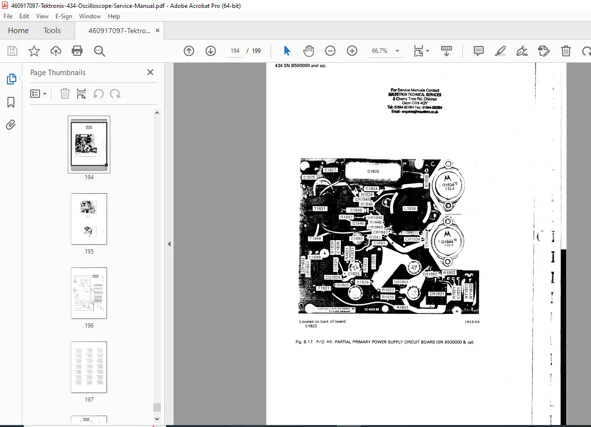
- PCB component layout
- Critical component identification
- Test point locations
- Adjustment locations
🔧 TEKTRONIX 434 KEY FEATURES
Storage Technology:
- Variable persistence storage
- Extended viewing time without continuous refresh
- Ideal for single-shot events
- Low-frequency waveform capture
- Transient analysis capability
Dual-Channel Operation:
- Simultaneous waveform viewing
- Channel A and B inputs
- Chopped or alternate display modes
- Independent vertical controls
- Add/subtract modes
Professional Grade:
- Laboratory-quality measurements
- Precision timebase
- Calibrated vertical deflection
- High reliability design
- Serviceable construction
💡 APPLICATIONS
Common Uses:
- Electronic circuit testing and debugging
- Signal analysis and measurement
- Educational laboratory equipment
- Transient waveform capture
- Low-frequency event recording
- Audio and video circuit testing
- Power supply ripple measurement
- Pulse and timing analysis
👥 ESSENTIAL FOR TECHNICIANS
This manual is critical for:
- Electronics Technicians repairing test equipment
- Biomedical Equipment Technicians servicing medical oscilloscopes
- Test Equipment Repair Facilities specializing in vintage instruments
- Engineering Technicians maintaining lab equipment
- Technical Schools teaching oscilloscope repair
- Vintage Equipment Collectors restoring classic Tektronix scopes
- Amateur Radio Operators maintaining test gear
- Electronics Hobbyists with component-level repair skills
🏭 TEKTRONIX QUALITY
Manufacturer Heritage:
- Tektronix: Industry leader in test equipment
- Known for durability and reliability
- Extensive service documentation
- Component-level serviceability
- Modular construction
- Professional-grade instrumentation
🛠️ SERVICE CAPABILITIES
Maintenance Support:
- Complete circuit documentation
- Adjustment procedures
- Calibration specifications
- Parts identification
- Troubleshooting flowcharts
Repair Procedures:
- Component-level repair guidance
- Signal tracing techniques
- Voltage measurement points
- Critical waveform analysis
- Performance verification tests
📐 TECHNICAL COMPLEXITY
Analog Circuit Technology:
- Vacuum tube circuits (CRT and possibly signal)
- Discrete transistor circuits
- Analog storage technology
- High-voltage power supplies
- Precision analog amplifiers
Service Requirements:
- Electronic test equipment needed
- Voltage measurement capability
- Waveform analysis tools
- Component testing equipment
- Safety equipment for high voltage work
⚙️ CIRCUIT SECTIONS COVERED
Major Subsystems:
- Low voltage power supplies (+5V, ±15V)
- High voltage supplies (CRT voltages)
- Vertical preamplifiers and attenuators
- Main vertical amplifiers
- Horizontal deflection system
- Timebase and sweep generators
- Trigger circuits and comparators
- Storage target control
- CRT drive circuits
- Calibration oscillator
🔍 DIAGNOSTIC FEATURES
Troubleshooting Aids:
- Symptom-based diagnostic charts
- Voltage tables and test points
- Expected waveforms at key points
- Component failure modes
- Performance verification procedures
Test Equipment Required:
- Digital multimeter
- Function/waveform generator
- Frequency counter
- Reference oscilloscope
- High-voltage probe
- Isolation transformer (recommended)
📊 VINTAGE INSTRUMENT RESTORATION
Collector Information:
- Classic Tektronix instrument
- Analog storage technology
- Historically significant design
- Restorable with proper documentation
- Parts availability considerations
- Vintage test equipment community support
⚠️ SAFETY CONSIDERATIONS
High Voltage Warnings:
- CRT operation involves kilovolts
- Discharge procedures required
- Capacitor stored energy hazards
- X-ray radiation precautions
- Proper grounding essential
Service Precautions:
- Qualified technician required
- Safety equipment necessary
- High voltage training recommended
- Follow all safety procedures
- CRT implosion hazard
🔬 ANALOG STORAGE TECHNOLOGY
Storage CRT Operation:
- Bistable storage phosphor
- Variable persistence capability
- Flood gun maintains display
- Writing gun creates stored image
- Erase function clears storage mesh
- Unique viewing capabilities for era
📖 MANUAL FORMAT
Scanned Documentation:
- High-resolution 300 DPI scans
- Complete factory manual reproduction
- All diagrams and schematics included
- Searchable PDF format
- Printable for workshop use
💼 PROFESSIONAL DOCUMENTATION
Factory Service Manual:
- Official Tektronix publication
- Complete technical information
- Professional troubleshooting procedures
- Calibration to factory specifications
- Authorized service reference
⚡ INSTANT DOWNLOAD – SERVICE VINTAGE TEKTRONIX OSCILLOSCOPES TODAY! This comprehensive 199-page Tektronix factory service manual provides complete technical documentation for the 434 analog storage oscilloscope. From theory of operation through component-level troubleshooting and complete schematics, everything needed for professional service and restoration is included. Download immediately and gain expert-level knowledge for Tektronix 434 oscilloscope repair and calibration!
Pricing Rationale:
- 199 pages of technical documentation
- Vintage/classic test equipment
- Complete schematics and diagrams included
- Analog storage oscilloscope technology
- Factory official service manual
- Component-level repair information
- Calibration procedures included
- Specialized test equipment documentation
- Niche collector/restoration market
- Essential for vintage Tektronix maintenance
- Scanned archival quality
- Professional service reference