Tektronix TAS 455 TAS 465 Analog Oscilloscope Service Manual PDF
Original price was: $95.00.$30.95Current price is: $30.95.
Complete Tektronix TAS 455 and TAS 465 analog oscilloscope instruction and service manual covering 100MHz dual-channel oscilloscopes. This comprehensive 260-page technical guide includes detailed operation procedures, performance verification, calibration adjustments, troubleshooting diagnostics, circuit theory, block diagrams, and complete specifications. Essential reference for electronics technicians, test equipment service engineers, and oscilloscope repair specialists.
Description
Tektronix TAS 455 TAS 465 Analog Oscilloscope Service Manual PDF DOWNLOAD
DESCRIPTION:
Official Tektronix TAS 455 & TAS 465 Service Manual – Complete Technical Documentation for Analog Oscilloscopes
This is the official Tektronix TAS 455 and TAS 465 Analog Oscilloscope Instruction Manual (Part Number 070-8523-05, 1992 edition, 260 pages) published by Tektronix, Inc., providing comprehensive technical documentation for these professional 100MHz dual-channel analog oscilloscopes. This essential service manual combines operator instructions with complete service procedures for qualified technicians maintaining and repairing Tektronix TAS series oscilloscopes.
⚠️ IMPORTANT SERVICE WARNING: The servicing instructions are for use by qualified personnel only. To avoid personal injury, do not perform any servicing unless you are qualified to do so. Refer to the Safety Summary prior to performing service.
WARRANTY: Tektronix provides a 3-year warranty covering defects in materials and workmanship from date of shipment, demonstrating the quality and reliability of these professional test instruments.
📋 COMPREHENSIVE MANUAL COVERAGE – COMPLETE SECTION BREAKDOWN:
PREFACE (Pages i to viii)
- Warranty Information:
- 3-year comprehensive warranty coverage
- Warranty conditions and exclusions
- Repair and replacement policy
- Customer responsibilities for service
- Related Manuals:
- User interface documentation
- Application notes references
- Probe selection guides
- Calibration procedure supplements
- Safety Summary:
- High voltage safety warnings
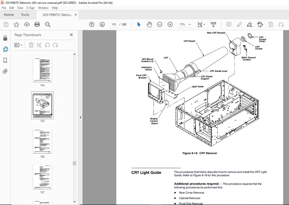
- CRT implosion hazards
- Electrical shock prevention
- Servicing safety precautions
- Grounding requirements
- Symbols and Terms:
- Safety symbol definitions
- Technical terminology
- Abbreviation reference
SECTION 1: PRODUCT DESCRIPTION (Pages 1-1 to 1-9)
- Equipment Description:
- TAS 455 and TAS 465 analog oscilloscope overview
- 100MHz bandwidth dual-channel design
- AUTOSET automatic setup feature
- Delayed sweep with delayed triggering capability
- Single sequence acquisition mode
- Waveform math functions (add, subtract, multiply)
- Video trigger capability
- Intended Use:
- General purpose electronic measurement
- Design verification and debugging
- Production testing
- Field service and repair
- Educational and training applications
- Product Description:
- Compact benchtop design
- Advanced trigger system features
- Digital readout display
- Menu-driven operation
- Front panel setup memory
- Special Precautions:
- Maximum input voltage limits
- CRT care and handling
- Environmental operating conditions
- Storage and transportation requirements
SECTION 2: USER INTERFACE (Pages 2-1 to 2-9)
- Function Overview:
- Menu-driven operation system
- Quick-access button layout
- Front panel organization
- Entry Formats Using Input Dials:
- Rotary encoder operation
- Numeric entry procedures
- Range selection methods
- Input of AUTOSET MESSAGE:
- Automatic signal detection
- Auto-configuration algorithms
- Override and manual adjustment
- Key Layout and Functions:
- Power and display controls
- Vertical system controls
- Horizontal system controls
- Trigger system controls
- Vertical System:
- Channel 1 and Channel 2 controls
- Volts/division settings
- Vertical position adjustment
- Input coupling (AC, DC, GND)
- Bandwidth limiting
- Channel inversion
- Add, subtract, multiply math functions
- Horizontal System:
- Timebase settings (seconds/division)
- Horizontal position control
- Magnification (zoom) function
- X-Y mode operation
- Delayed sweep configuration
- Trigger System:
- Trigger source selection (CH1, CH2, EXT, LINE)
- Trigger level adjustment
- Trigger mode (AUTO, NORMAL, SINGLE SEQ, TV)
- Trigger coupling (AC, DC, HF REJ, LF REJ)
- Trigger slope selection
- Video trigger standards (NTSC, PAL, SECAM)
- Delayed trigger capability
- Measurement Cursors:
- Time measurement cursors
- Voltage measurement cursors
- Delta readouts
- Cursor positioning controls
- Options:
- Front panel cover and pouch accessories
- 10X/1X switchable voltage probes (100MHz)
- Additional probes and accessories
- Rack mount kits
SECTION 3: OPERATION (Pages 3-1 to 3-30)
- Getting Started:
- Quick Start: Power-up and basic signal display
- Installation: Benchtop placement and rack mounting
- Select and Deselect Input Channels: Channel activation
- Using the Menus: Menu navigation and selection
- Connection of a Signal: Proper probe connection techniques
- At a Glance:
- Front panel overview diagram
- Power and Display Controls
- Menu Select Buttons
- Signal Inputs and Outputs (CH1, CH2, EXT TRIG, CH1 OUTPUT)
- Vertical Controls
- Horizontal Controls
- Trigger Controls
- Miscellaneous Controls
- Menu Map (complete menu structure)
- Readout Display interpretation
- Using Basic Features:
- Displaying Repetitive Signals: Stable waveform acquisition
- Magnifying Your Signal: Horizontal expansion techniques
- Displaying Video Signals: TV waveform triggering and viewing
- Using Single Sequence: Single-shot capture mode
- Performing Waveform Math: Mathematical operations on channels
- Using Delayed Sweep with Delayed Triggering:
- Main sweep and delayed sweep operation
- Intensified zone indication
- Delayed trigger setup
- Storing Help: On-screen help system
- Saving and Recalling Front Panel Setups:
- Storing setup configurations
- Recalling saved setups
- Erasing setup memories
- Taking Measurements:
- Taking Time Related Measurements:
- Period measurement techniques
- Frequency calculation
- Pulse width measurement
- Rise/fall time measurement
- Delay measurements between signals
- Measuring Frequency and Period: Cursor-based measurements
- Measuring Pulse Width: Positive and negative pulse measurements
- Taking Rise/Fall Time Measurements: 10%-90% measurement techniques
- Taking Voltage Related Measurements:
- Peak-to-peak voltage
- RMS voltage estimation
- DC voltage levels
- Absolute Voltage Measurement: Single cursor measurements
- Delta Voltage Measurement: Differential measurements using dual cursors
- Taking Time Related Measurements:
SECTION 4: PERFORMANCE (Pages 4-1 to 4-12)
- General Specifications:
- Bandwidth: DC to 100 MHz (-3 dB)
- Rise time: ≤3.5 ns
- Vertical deflection: 2 channels
- Sensitivity: 2 mV/div to 5 V/div (1-2-5 sequence)
- Vertical accuracy: ±3% (±2°C from calibration temperature)
- DC gain accuracy: ±3%
- Input impedance: 1 MΩ ±2%, 20 pF typical
- Maximum input voltage: 400V (DC + peak AC)
- Input coupling: AC, DC, GND
- Bandwidth limit: 20 MHz ±3 MHz
- Channel isolation: ≥40 dB at 100 MHz
- Characteristics:
- DC Coupled Bandwidth: Frequency response curves
- Timebase Specifications:
- Sweep speed: 5 s/div to 5 ns/div
- Sweep accuracy: ±3%
- Delayed sweep: 50 ns/div to 5 s/div
- Delay time accuracy: ±3%
- X-Y phase shift: ≤3° at 100 kHz
- Trigger System Specifications:
- Internal trigger sensitivity: 0.5 div to 100 MHz
- External trigger sensitivity: 200 mV DC to 100 MHz
- Trigger level range: Internal ±5 divisions
- Trigger modes: Auto, Normal, Single, TV
- TV standards: NTSC, PAL, SECAM
- Display Specifications:
- CRT: 8 × 10 cm (rectangular)
- Graticule: 8 divisions horizontal × 10 divisions vertical
- Writing speed: Typically 1000 div/μs
- Maximum acceleration voltage: 14 kV
- Trace rotation: Front panel adjustment
- Environmental Specifications:
- Operating temperature: 0°C to +50°C
- Non-operating temperature: -40°C to +75°C
- Operating humidity: 5% to 90% RH (non-condensing)
- Operating altitude: Up to 3,000 meters (9,900 feet)
- Physical Specifications:
- Dimensions: Approximately 323 mm W × 152 mm H × 447 mm D
- Weight: Approximately 7.7 kg (17 lbs)
- Power Requirements:
- Line voltage: 90-132 VAC or 180-250 VAC (auto-ranging)
- Line frequency: 48-440 Hz
- Power consumption: Maximum 70 Watts
SECTION 5: THEORY OF OPERATION (Pages 5-1 to 5-12)
- Service Strategy:
- Troubleshooting methodology
- Block diagram analysis
- Signal tracing techniques
- Block Level Descriptions:
- Overall system architecture
- 1. Acquisition Signal Path:
- Input attenuators and amplifiers
- Vertical processing
- CRT drive circuitry
- 2. Acquisition Control:
- Microprocessor control system
- AUTOSET algorithm implementation
- 3. Timebase:
- Horizontal sweep generation
- Delay line operation
- 4. Trigger Signal:
- Trigger detection circuits
- Trigger comparators
- Holdoff circuitry
- 5. Power Supply:
- Multiple voltage generation
- CRT high voltage supply
- Power supply regulation
- 6. Menu:
- User interface processor
- Display generation
- 7. Digital Storage (if applicable):
- Waveform digitization
- Memory architecture
- Schema:
- System block diagrams
- Simplified signal flow
- Major subsystem interconnections
SECTION 6: MAINTENANCE (Pages 6-1 to 6-12)
- General Precautions:
- Electrostatic discharge (ESD) protection
- Component handling precautions
- Tool requirements
- Brief Performance Check Procedures:
- Quick functional verification tests
- Go/no-go testing
- Using the Performance Tests Procedures:
- Detailed test setups
- Equipment required for testing
- Test point locations
- Conventions:
- Nomenclature used in procedures
- Measurement techniques
- Adjustment methods
SECTION 7: PERFORMANCE (Pages 7-1 to 7-8)
- Introduction:
- Purpose of performance verification
- When to perform tests
- Required test equipment list
- Using the Brief Performance Check and the Performance Tests:
- Performance verification flowchart
- Pass/fail criteria
- Troubleshooting decision trees
- General Instructions:
- Test setup configurations
- Environmental conditions
- Warm-up requirements (typically 20 minutes)
- Calibration reference standards
- Conventions:
- Test point naming conventions
- Measurement tolerance interpretation
- Adjustment procedure format
SECTION 8: ADJUSTMENTS (Pages 8-1 to 8-8)
- Introduction:
- Purpose of adjustment procedures
- When adjustments are required
- Proper adjustment sequence
- General Instructions:
- Required test equipment for adjustments
- Precision signal generators
- Digital voltmeters
- Frequency counters
- 1. Processor Circuit:
- Microprocessor clock adjustments
- Reset circuit verification
- 2. Alignment Circuit:
- Trace alignment procedures
- Geometry correction
- 3. Delay Signal:
- Delay line optimization
- Trigger positioning accuracy
- 4. DAC:
- Digital-to-analog converter calibration
- Linearity adjustments
- 5. Vertical:
- Vertical amplifier calibration
- DC offset nulling
- AC coupling compensation
- Bandwidth optimization
- 6. Horizontal:
- Sweep linearity calibration
- Timebase accuracy adjustment
- 7. Trigger:
- Trigger level accuracy
- Trigger sensitivity optimization
- 8. Power Supply:
- Voltage regulation adjustments
- Ripple minimization
- 9. CRT:
- Focus adjustment
- Intensity calibration
- Astigmatism correction
- Trace rotation (mechanical)
SECTION 9: POWER LINE (Pages 9-1)
- Installation:
- Power cord selection
- Grounding requirements
- Line voltage configuration
- Quick Start:
- Initial power-up procedures
- Smoke test (initial inspection)
- Select and Deselect Input Channels:
- Power-on defaults
- Channel activation sequence
SECTION 10: ACCESSORIES (Pages 10-1 to 10-4)
- Standard and Optional Accessories:
- Included Accessories:
- Two 10X passive probes (P6139A or equivalent, 100 MHz bandwidth)
- Probe compensation fixture
- Front panel cover and accessory pouch
- Power cord
- Instruction manual
- Certificate of calibration
- Optional Accessories:
- Current probes
- High voltage probes (up to 40 kV)
- Active probes (FET input, GHz bandwidth)
- Differential probes
- Logic probes
- Rackmount kits
- Transit case
- Camera systems for waveform photography
- Accessory Probes:
- Probe specifications and applications
- Probe compensation procedures
- Probe attenuation factors
- Bandwidth considerations
- Included Accessories:
APPENDICES AND REFERENCE SECTIONS:
- Diagrams and Schematics:
- Complete circuit schematics (foldout diagrams)
- Component location drawings
- PCB layout diagrams
- Wiring harness interconnections
- Connector pinout diagrams
- Parts Lists:
- Replaceable components with part numbers
- Cross-reference to schematics
- Recommended spare parts inventory
- Calibration Data:
- Factory calibration values
- Adjustment ranges
- Performance limits
📄 FILE DETAILS:
Manual Name: TAS 455 & TAS 465 Analog Oscilloscopes Instruction Manual
Part Number: 070-8523-05
Publication Date: 1992 (Copyright Tektronix, Inc.)
Models Covered:
- Tektronix TAS 455 – 100MHz Dual-Channel Analog Oscilloscope
- Tektronix TAS 465 – 100MHz Dual-Channel Analog Oscilloscope
Bandwidth: DC to 100 MHz (-3 dB)
Channels: 2 independent vertical channels
Key Features: - AUTOSET automatic setup function
- Delayed sweep with delayed triggering
- Single sequence (single-shot) acquisition
- Waveform math (add, subtract, multiply)
- Video trigger (NTSC, PAL, SECAM)
- Digital readout display
- Front panel setup memory
- Measurement cursors (time and voltage)
Applications: General purpose electronic testing, design verification, production testing, field service, education
Manual Type: Combined operator and service manual
Manual Quality: Professional PDF with detailed technical illustrations, block diagrams, circuit schematics, and adjustment procedures
Total Pages: 260 pages
File Size: Approximately 3.9 MB
Format: PDF (encrypted with print and copy allowed)
Publisher: Tektronix, Inc., Wilsonville, Oregon, USA
Copyright: © 1992 Tektronix, Inc.
Trademark: TEKTRONIX and TEK are registered trademarks of Tektronix, Inc.
🔧 WHO NEEDS THIS MANUAL:
This Tektronix TAS 455/465 manual is essential for:
- Electronics technicians and engineers
- Test equipment service specialists
- Oscilloscope repair technicians
- Calibration laboratory personnel
- Educational institutions (electronics labs and training)
- R&D engineers using Tektronix equipment
- Field service engineers
- Biomedical equipment technicians
- Industrial maintenance departments
- Vintage test equipment collectors and restorers
- Anyone owning or servicing Tektronix TAS 455 or TAS 465 oscilloscopes
⚡ KEY TECHNICAL INFORMATION INCLUDED:
✓ Complete operating instructions for all functions and features
✓ AUTOSET automatic setup algorithm explanation
✓ Delayed sweep and delayed triggering procedures
✓ Single sequence (single-shot) operation
✓ Waveform math operations (add, subtract, multiply)
✓ Video signal triggering for TV waveforms
✓ Measurement cursor usage for time and voltage
✓ Front panel setup save/recall procedures
✓ Complete performance specifications (bandwidth, sensitivity, accuracy)
✓ Theory of operation with block diagrams
✓ Performance verification test procedures
✓ Detailed adjustment and calibration procedures
✓ Troubleshooting methodology and fault isolation
✓ Complete circuit schematics with component values
✓ Parts lists with Tektronix part numbers
✓ Probe selection and compensation procedures
💎 SPECIAL FEATURES:
Dual-Model Coverage: Single manual covers both TAS 455 and TAS 465 oscilloscope models, providing comprehensive documentation for both instruments.
AUTOSET Feature: Detailed explanation of Tektronix’s innovative AUTOSET function that automatically configures the oscilloscope for stable waveform display.
100MHz Bandwidth: Professional-grade analog oscilloscope suitable for general electronics work, digital circuit debugging (up to ~20 MHz signals), and RF measurements.
Combined Operator/Service Manual: Unique combination of user operation instructions with complete service procedures, providing value for both operators and technicians.
Delayed Sweep Capability: Advanced feature for examining specific portions of waveforms with time expansion, essential for timing analysis and glitch detection.
Video Triggering: Specialized trigger modes for NTSC, PAL, and SECAM video signals, useful for television and video equipment servicing.
Waveform Math: Mathematical operations between channels enable differential measurements and signal comparison.
Digital Readout: On-screen display of measurement values, trigger settings, and operating parameters for enhanced usability.
3-Year Warranty: Exceptional warranty coverage demonstrating Tektronix’s confidence in product quality and reliability.
Classic Tektronix Design: Part of Tektronix’s legendary analog oscilloscope lineage, known for reliability, performance, and ease of service.
⚠️ IMPORTANT SAFETY AND SERVICE NOTES:
Qualified Personnel Only: This manual contains servicing instructions for use by qualified personnel only. Servicing should only be performed by those trained in oscilloscope repair.
High Voltage Hazard: CRT oscilloscopes contain high voltages (up to 14 kV for CRT acceleration). Lethal voltages present even after power off due to capacitor charge retention.
CRT Implosion Risk: Cathode ray tubes are evacuated glass envelopes under vacuum. Improper handling can result in implosion causing flying glass and injury.
ESD Precautions: Electrostatic discharge can damage sensitive semiconductor components. Proper ESD protection (wrist straps, conductive mats) required during service.
Maximum Input Voltage: Do not exceed 400V (DC + peak AC) on vertical inputs to prevent damage to input circuitry.
Probe Compensation Required: Probes must be properly compensated using the front panel calibrator for accurate measurements.
Warm-Up Time: Allow 20-minute warm-up for accurate measurements and before performing calibration adjustments.
Grounding Essential: Oscilloscope must be properly grounded through 3-wire power cord for safety and to prevent ground loop noise.
Service Warranty Impact: Servicing by non-Tektronix personnel or unauthorized modifications will void manufacturer warranty.
Proper Tools Required: Service procedures require specialized test equipment including precision signal generators, frequency counters, and calibrated DVMs.
⚡ INSTANT DOWNLOAD – ESSENTIAL FOR TEKTRONIX TAS 455/465 OWNERS! Get immediate access to this comprehensive Tektronix service manual and properly operate, maintain, and service your TAS 455 or TAS 465 analog oscilloscope. Download now and keep your test equipment running at peak performance with factory-authorized procedures used by Tektronix service engineers worldwide