Terex Crane AC40/2-AC40/2L EN 13000 2010 Maintenance & Operator’s Manual PDF
$34.95
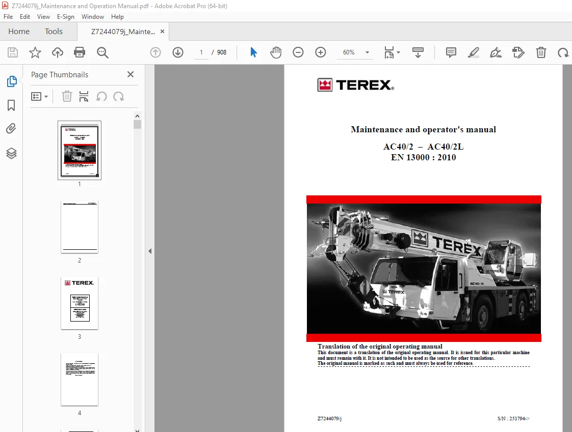
Terex Crane AC40/2-AC40/2L EN 13000 2010 Maintenance & Operator’s Manual – PDF DOWNLOAD
Description
Terex Crane AC40/2-AC40/2L EN 13000 2010 Maintenance & Operator’s Manual – PDF DOWNLOAD
FILE DETAILS:
Terex Crane AC40/2-AC40/2L EN 13000 2010 Maintenance & Operator’s Manual – PDF DOWNLOAD
Language : English
Pages : 908
Downloadable : Yes
File Type : PDF
IMAGES PREVIEW OF THE MANUAL:
TABLE OF CONTENTS:
Terex Crane AC40/2-AC40/2L EN 13000 2010 Maintenance & Operator’s Manual – PDF DOWNLOAD
AC40/2 – AC40/2L 1
Maintenance operation work sheet 5
Table of contents 7
Table of contents Chapter 01 8
Table of contents Chapter 02 9
Table of contents Chapter 03 11
Table of contents Chapter 04 13
Table of contents Chapter 05 22
Table of contents Chapter 06 26
Table of contents Chapter 07 27
Table of contents Chapter 08 28
Table of contents Chapter 09 29
Table of contents Chapter 10 30
Table of contents Chapter 11 31
Chapter 1 Information 33
Technical specification 35
Operator’s comfort 36
Constructors Identity Plate locations 37
How to read the TEREX CRANES vehicle code
number 38
Conversion Table in metric units 39
Data Commercial 40
AC40/2 41
AC40/2L 63
Chapter 2 General recommendations 87
Notes importantes 89
Bungee jumping from cranes is dangerous 90
Traveling cranes near airports 91
Assembling and disassembling an auxiliary winch 94
Recommendations for capacity chart reading 95
Particular recommendations when
lifting loads on free on wheels 96
Particular recommendations when lifting loads on
outriggers 97
Pad lifting 98
BRAKING SYSTEM 99
1 / Visual check 99
2 / Correct operation test 100
3 / Efficiency testing 100
Running in the brake linings 102
Specify and check the counterweight combination
depending on the load table selected before lifting 103
Lifting counterweight configuration 104
WEIGHING THE CRANE 111
Operation regulations for the machine on highways 112
Ageing control of the device 113
L M I override 113
Various information for users of the dual fuel
system 114
Explosive atmospheres 117
Warning for users of man baskets 118
Chapter 3 Safety rules 119
Safe operating practices for mobile crane users 120
Operator’s responsibility 121
Banksman ‘s responsibility 122
Standard crane signals 123
Responsibilities of all crew members 124
Management responsibility 124
Planning the job 125
Operator’s safety check 126
Setting the work safety perimeter 128
List of Adhesive Labels 137
Pictogram 140
Majorities on the safety 146
Access and cleanliness 147
Driving 148
Maintenance 151
Fire prevention in the engine compartment 152
Electricity 154
Hydraulics 156
Effects of hydraulic oil expansion 157
Safety instructions with the tires 161
EXAMINATION OF RIMS AND WHEELS 161
In-Service Inspection of Demountable rims 164
Inspection Procedure 164
Safety Precautions 165
Wind force 169
Determine wind speed on the worksite 170
Determine wind speed on the crane 170
Recommendations for washing the crane 170
Crane inspection 171
Inspection 172
Winch inspection 173
1 0/ Calculating the remaining theoretical length of use 173
1 1/ Wear rate based on the theoretical length of use of
the winches 174
1 2/ Determination of the conditions of use 175
1 3/ Determination of the actual hours of use 175
1 4/ Determination of the wear rate based on the
theoretical length of use of the winches 177
1 5/ Inspection 179
Rear-view and front-view mirrors 182
Emergency exit 182
Check on welds 183
Chapter 4 Controls and operation 199
Crane layout 201
Operator’s cab 202
Controls and operation – Carrier cab 203
1/ Steering wheel 204
2 / Accelerator pedal 204
3 / Service brake pedal 204
4 / Antitheft ignition switch 205
5 / Direction indicators – horn – lights 205
6 / Electric retarder control 207
7 / Windscreen wiper/washer control 208
8 / Gear selector pad 208
9 / Parking brake 211
10 / Emergency brake 211
11 / Steering column lock/release/adjustment control 211
12 / Cab heating and air conditioning controls 211
13 / 12- and 24-volt sockets 212
14 / Diagnostic socket 212
15 / Rear-view mirror control (2 main mirrors) 212
18 / Diesel – NRD (Non Road Diesel) selection
indicator (optional) 212
19 / Rear-wheel steer switch and indicator light 213
20 / Automatic suspension levelling switch and
indicator 213
21 / Suspension locking switch (Locked position) 214
22 / Front-axle dog clutching switch and indicator 215
23 / Hand throttle switch and indicator 215
24 / Suspension lift / lower switch 216
25 / Suspension lift / lower switch
Rear Left 216
27 / Inner-axle differential switch and indicator 216
28 / Suspension lift/lower switch
Front right 217
29 / Suspension lift/lower switch 217
31 / Diesel/NRD (Non Road Diesel) selection switch
and indicator (dual-fuel option) 218
32 / Hazard warning light switch and indicator 219
33 / Axle ABS disconnect switch 219
36 / Rear-wheel steer lock/release switch 220
37 / Upper cab/Carrier cab select switch and
indicator 220
38 / Outrigger select switch and indicator 221
39 / Rotating beacon switch and indicator 221
45 / Carrier cab seat adjustment 222
50 / Electronic speedometer 223
51 / Scrolling display 223
52 / Fuel gauge 224
52A / Low fuel warning light 224
53 / Tachometer 224
54 / Front-brake air pressure gauge 225
55 / Rear-brake air pressure gauge 225
60 / Gearbox fault warning light 226
61 / Gearbox oil temperature warning light (Red) 226
62 / Main power-steering system warning light
(Red) 227
63 / Backup power-steering system warning light
(Red) 227
66 / Engine pre-alarm warning light 228
67 / “Switch off engine” and “Engine fault”
warning lights (Red) 229
68 / Battery charge warning light (Red) 229
69 / Parking-brake air pressure warning light
(Red) 230
70 / Electric retarder indicator 230
72 / Locked front suspension indicator 231
73 / Locked rear suspension indicator 231
74 / Axle ABS fault warning light or ABS not
selected 232
75 / Trailer ABS fault warning light 232
76 / Front-axle dog clutching indicator 232
78 / Front fog lamp indicator
233
79/ Sidelights indicator (Green) 233
80 / Carrier direction indicator light (Green) 233
81 / Trailer direction indicator light (Green) 233
82 / Main (full) beam indicator (Blue) 234
83 / Rear fog lamp indicator (Amber) 234
84 / Front-brake air-pressure indicator (Red) 235
85 / Rear-brake air-pressure indicator (Red) 235
Left-hand outriggers control panel 237
90 / Outrigger pads or beams selector switch 237
91 / Speed control switch 237
92 / Front-right outrigger pad lift/lower selector
switch 237
93 / Rear-right outrigger pad lift/lower selector switch 237
94 / Front-left beam extension/retraction or front-left
pad lift/lower selector switch 237
95 / Rear-left beam extension/retraction or rear-left
pad lift/lower selector switch 237
96 – Electronic level indicator 238
97 / Emergency shutoff 238
98 / Precision threshold selector – 10° – 5° – 1° 238
99 / Precision threshold display 238
Right-hand outriggers control panel 239
100 – Outrigger pads or beams selector switch 239
101 / Speed control switch 239
102 / Rear-left outrigger pad lift/lower selector switch 239
103 / Front-left outrigger pad lift/lower selector
switch 239
104 / Rear-right beam extension/retraction or rearright
pad lift/lower selector switch 239
105 / Front-right beam extension/retraction or frontright
pad lift/lower selector switch 239
106 – Electronic level indicator 240
107 / Emergency shutoff 240
108 / Precision threshold selector – 10° – 5° – 1°
240
109 / Precision threshold display 240
Controls and operation –
Upper cab 241
200 / Steering wheel for front wheels 242
201 / Accelerator pedal 242
202 / Service brake pedal 242
203 / Free slewing pedal 242
204 / Armrest release handle 242
205 / Warning horn 243
206 / Seat safety device override switch 243
207 / Parking brake button 243
208 / Rear-wheel steering control 244
209 / Slewing/telescoping joystick 245
209 A / “Auxiliary winch with simultaneous dual-winch
operation” option Joystick: Slewing/Lifting 2 or
Telescoping 246
210 / Joystick: Lifting 1/Derricking 253
210 A / “Auxiliary winch without simultaneous dualwinch
operation” Joystick: Lifting 1 or Lifting
2/Derricking 254
211 / Level indicator
254
212 / Slewing micro-speed control 254
214 / Gear panel 255
215 / Cigarette lighter 256
216 / Ignition key switch 256
217 / Emergency engine shutoff 256
218 / AC40/2L Telescoping sequence switch 257
219 / AC40/2 Boom key 259
220 / Heater control dial 261
222 / General alarm warning light 262
223 / Clogged hydraulic filter warning light 262
225 / Locked front suspension indicator 263
226 / Locked rear suspension indicator 263
228 / Over-the-rear, in-line operation indicator 263
234 / Front-axle dog clutching indicator 264
240 / Shunt key 265
241 / Anti-two block shunt switch 267
242 / Derricking-up reactivation switch 267
243 / Setup button
268
250 / Front windscreen wiper switch 270
251 / Cab roof windscreen wiper switch 270
252 / Windscreen washer switch
270
253 / Work light switch 270
254 / Fan switch 270
257 / Auxiliary winch select switch 270
258 / Free slewing switch 271
260 / Counterweight cylinder lift/lower switch 273
261 / Counterweight lock/unlock switch 273
262 / Control for additional lights (Optional) 273
270 / Front-left outrigger pad and front-left beam
control switch 274
271 / Front-right pad and front-right beam control
switch 275
272 / Rear-left outrigger pad and rear-left beam
control switch 276
273 / Rear-right outrigger pad and rear-right beam
control switch 277
274 / Crane functions or outriggers selector switch 278
275 / Outrigger extension or outrigger pad selector
switch 278
276 / Front-suspension locking control 279
277 / Rear-suspension locking control 279
278 / Manual engine-speed control 280
286 / Front-axle dog clutching switch 280
287 / Rear-wheel steer lock release switch 280
288 / Hydraulic extension control (Optional) 280
Operating the machine 281
Introduction 281
Preliminary checks 282
Using the machine in cold conditions 284
Highway driving 286
On the worksite
288
Conditions for using the suspension locking system 290
Carrying a load 290
Hazards within the working area 291
Crane configuration 292
Configuration of the counterweights for use on road
or site 293
Using the counterweights when lifting 294
A1 / Setting down the chassis counterweights to give
a 2 x 12 t machine configuration 295
A1-1/ Removal on to the chassis of counterweight(s)
fixed to the upperstructure 296
A1-2/ Removing counterweight(s) from the chassis on
to the ground 299
B / Removing counterweights to obtain a 2 x 13 t
machine configuration 300
B-1/ Removal on to the chassis of counterweight(s)
fixed to the upperstructure
301
B-2/ Removing counterweight(s) from the chassis on
to the ground 303
C / Fitting pin-secured counterweight to the
upperstructure 304
D / Fitting all the counterweights to the
upperstructure 306
E/ Removing all the counterweights on to the
chassis 308
AC40/2 Couterweight arrangement 2,5t / 3,9t 312
AC40/2 Couterweight arrangement 2,5t 313
AC40/2 Couterweight arrangement 3,8t / 4,95t 314
AC40/2 Couterweight arrangement 2,5t / 3,9t 315
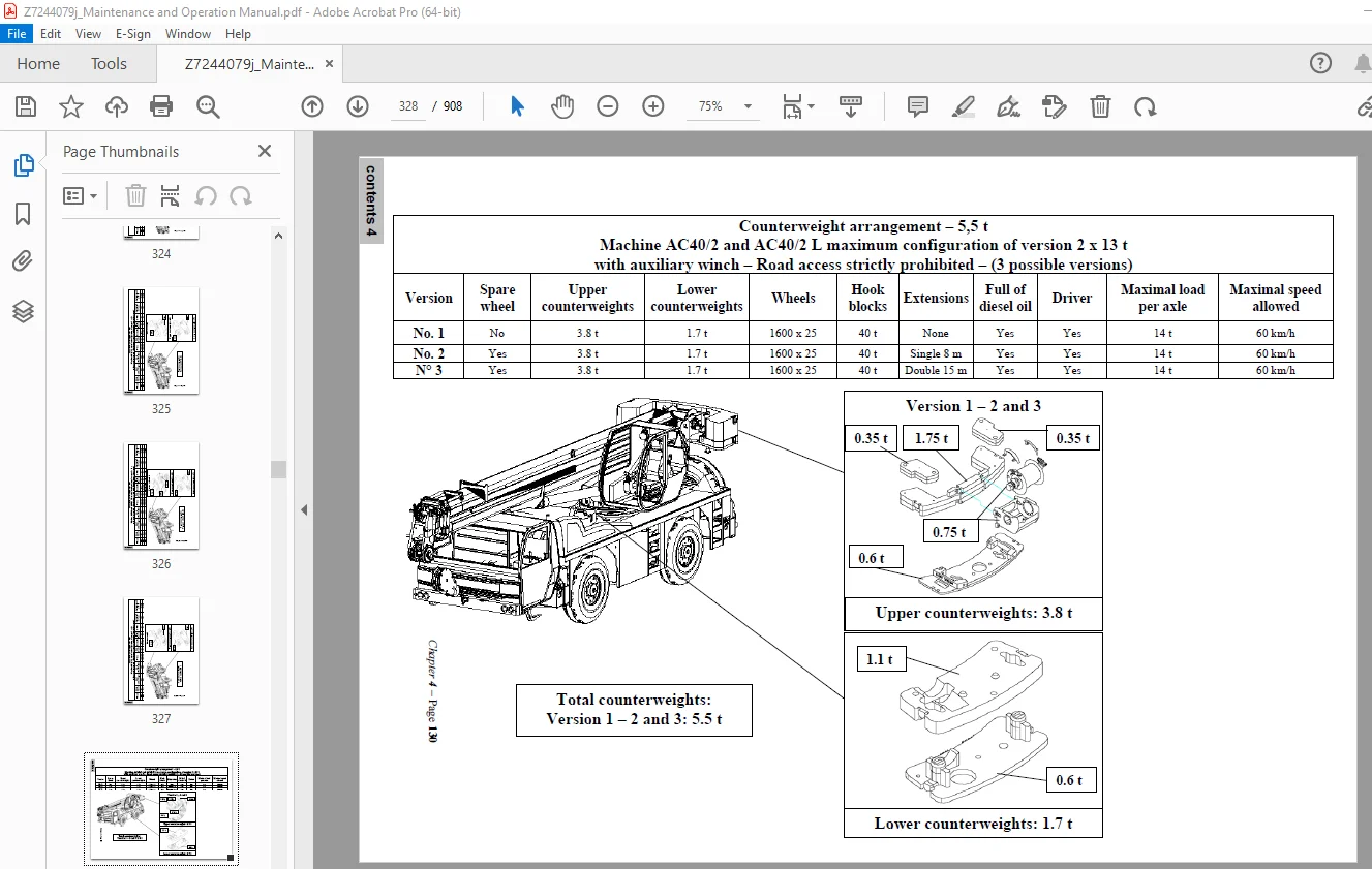
AC40/2 Couterweight arrangement 5,5t / 5,75t 316
AC40/2 Couterweight arrangement 5,5t 317
AC40/2L Couterweight arrangement 2,5t 318
AC40/2L Couterweight arrangement 2,5t 319
AC40/2L Couterweight arrangement 3,8t 320
AC40/2L Couterweight arrangement 3,8t 321
AC40/2L Couterweight arrangement 5,5t 322
AC40/2L Couterweight arrangement 5,5t 323
AC40/2L Couterweight arrangement 5,5t 324
AC40/2L Couterweight arrangement 5,5t 325
Assembling and disassembling an auxiliary winch 326
Ground stability 327
Setting up the machine on outriggers 329
Telescoping 330
Boom limits without load 331
Towing 331
Replacing a punctured or deflated tyre 332
Attaching the boom to its support and securing the
hook block 333
Jump starting 334
Replacing the batteries 335
Seat adjustment in the upper cab 336
Procedure for repriming and bleeding the diesel
system on a dual-fuel machine 337
Draining the fuel system 337
Reeving system 339
Reeving procedure 340
Reeving systems and hook blocks AC40/2 342
Reeving systems and hook blocks AC40/2 L 345
Replacing the hoist cable 348
Boom retaining sling 349
FOLDING AND DEPLOYING THE
EXTENSIONS 350
Machine with an 8 m extension 351
Deploying the 8m extension 351
Folding the 8 m extension 360
Machine with 15 m extension (8 m + 7 m) 365
Deploying the 8 m extension only 365
Folding the 8 m extension 374
Machine with 15m extension 379
Deploying the 8 m and 7 m extensions 379
Folding the 8 m and 7 m extensions 389
Method 1: Inclining the extensions using the lift
function 397
A – Inclining the 8 m extension 397
A1 – Inclining the 8 m extension to 20° 398
A2 – Inclining the 8 m extension to 40° 399
B – Inclining a 15 m extension 400
B1 – Inclining the 15 m extension to 20° 401
B2 – Inclining a 15 m extension to 40° 402
Method 2: Inclining the extensions using the
telescoping function 404
A – Inclining the 8 m extension 404
A1 – Inclining the 8 m extension to 20° 405
A2 – Inclining the 8 m extension to 40° 406
B – Inclining a 15 m extension 407
B1 – Inclining the 15 m extension to 20° 408
B2 – Inclining a 15 m extension to 40° 409
FOLDING AND DEPLOYING THE HYDRAULIC
EXTENSIONS (Optional) 411
Machine with an 8 m extension 412
Deploying the 8m extension 412
Folding the 8 m extension 423
Machine with 15 m extension 431
Deploying the 8 m and 7 m extensions 431
Folding the 8 m and 7 m extensions 437
ROOSTER SHEAVE 441
Reeving 443
Chapter 5 Maintenance 447
Maintenance 448
Levels of Maintenance 449
Maintenance general features 450
Tableau récapitulatif des entretiens 451
Regular service intervals 453
Preventive maintenance 455
Table: tightening torques for traditional steel screw
assemblies 457
Tightening torque for slotted nuts / spline nut 458
Slew ring attachment 459
Torque settings for slew rings screws and bolts 461
Checking slew ring wear 465
Measuring the tilting clearance 465
Details about the measurement 466
Acceptable wear limits 467
Engines 468
The engine’s data card is part of its identity papers 469
Transmission: convertor and powershift unit 470
Recommendations when carrying out maintenance work 471
Access to the chassis: 471
Overhead work 472
Personal protective equipment to be used for
maintenance procedures 474
List “A” – 10 h 475
Air filter Code A1 475
Winch cable Code A2 475
Hydraulic tank and fuel tank levels Code A3 476
Windscreen wiper liquid bottle Code A4 477
Engine Code A5 478
Engine radiator coolant level Code A6 479
Upper heating fuel tank Code A7 480
List “B” – 50 h 481
Slewing ring Code B1 481
Slewing ring toothing Code B2 481
Information sur la relubrification de la couronne (Intervalles et quantité) 482
Slewing sensor Code B3 483
Outrigger rams Code B4 483
Derricking cylinder Code B5 484
Counterweight lock cylinder Code B6 484
Boom and derricking system Code B7 485
Cleaning the machine Code B8 488
Transmission: convertor and powershift unit Code
B9 489
Drive shafts Code B10 490
Suspension rams Code B11 491
Tyre pressures Code B12 491
List “C” – 100h 492
Batteries Code C1 492
Wheel nut tightness Code C2 494
Slewing reducer gear motor Code C3 494
Combustion engine radiator Code C4 495
Ancillary component belt tensions and conditions
Code C5 495
Check the tightness of the axle torque arms Code
C6 496
Air filter Code C7 496
List “D” – 200 h 498
Air conditioning unit Code D1 498
Carrier cab Code D2 499
Check correct working order of parking brake and
service brakes Code D3 499
Winch reducer gear Code D4 500
Steering block D5 500
List “E” – 500 h 501
Telescoping chains E1 501
Telescoping cables Code E2 504
Hydraulic circuit filter Code E3 505
Steering Code E4 506
Slewing ring Code E5 506
Air dessicator Code E6 506
Axle gear reducer Code E7 507
Winch cable Code E8 507
“Three dead turns” limiter device Code E9 511
Brakes Code E10 512
Air bottles Code E11 512
Pipe Exhaust Code E12 513
Suspension filter Code E13 514
Greasing of front and rear axle connecting rods and
linkages E14 515
Axle differential unit Code E15 516
Dual-fuel option Code E16 516
Motor cowling cover Code E17 517
List “F” – 1000 h 518
Check all fasteners Code F1 518
Slewing reducer gear Code F2 518
Winch reducer gear Code F3 518
Boom section slide pads and pulleys Code F4 519
PLASTIC SHEAVES 520
Hydraulic circuit Code F5 521
Have the steering geometry checked by a TEREX
specialist Code F6 521
Air brake bottles Code F7 521
Electrical circuit Code F8 521
AEB Cycle Code F9 522
Flexibles, vérification Code F10 523
Hoses Code F10 524
Axle reducer gear Code F12 524
Have the suspension accumulators checked by a
TEREX specialist Code F13 525
List “G” -2000 h 526
Hydraulic tank Code G1 526
Counterweights Code G2 527
Brakes Code G3 527
Cooling circuits Code G4 527
Air conditioning unit Code G5 528
Upper heating fuel tank Code G6 528
Check on welds Code G7 529
Suspension filter Code G8 529
Air filter Code G9 529
Motor cowling cover Code G10² 530
List “H” – 5000 h 531
Pipe Exhaust Code H1 531
List “I” – 10000 h 532
Hoses Code I1 532
List “J” – 20000 h 532
Telescopic boom Code J1 532
Chapter 6 Fuel – Lubrifiants 533
Component capacities 534
Capacities 535
Filter elements 536
Oil chart 537
Chapter 7 Load moment indicator 539
ViewTech – Phase 3 541
Chapter 8 Schémas 0
CR108572E 0
CR108867A 0
CR107888D 0
CR107889 0
CR108671C 0
CR108679C 0
CR108011 0
CR108037A 0
CR108120A 0
CR108136A 0
CR108242A 0
Chapter 9 Maintenance booklet 0
Identification 0
Service intervals 0
Introduction 0
Maintenance liste “A” 0
Maintenance liste “B” 0
Maintenance liste “C” 0
Maintenance liste “D” 0
Maintenance liste “E” 0
Maintenance liste “F” 0
Maintenance liste “G” 0
Maintenance liste”H” 0
Maintenance liste “I” 0
Maintenance liste “J” 0
Chapter 10 Annexes 0
Dual fuel systems 0
Hoist blocks in service inspection 0
1 – INSPECTING THE HOOKS 0
2 – INSPECTING THE CROSS-MEMBERS 0
3 – INSPECTING THE SHEAVE PINS 0
4 – INSPECTING THE CARRIER PLATES 0
5 – INSPECTING THE SHEAVES 0
6 – WELDING / REPAIRS 0
7 – SAFETY INSTRUCTIONS (ILLUSTRATED SUMMARY) 0
Safety latch 0
SUITABILITY CHECK 0
Description of the fault codes 0
Chapter 11 Special products studies 0
Alizé 3 0
1 GENERAL PRESENTATION 0
2 SYSTEM FEATURES 0
3 USE 0
4 FITTING / WIRING 0
5 SERVICE / MAINTENANCE 0
6 PARAMETING THE SYSTEM – ACCESS CODE 0
Central lubrication PICO 0
SPS Severe Cold Option 0
SPS 02268 Emergency shutoff Option 0
schemas_gb pdf 0
schemas_gb 617
CR108572eGB 0
1 0
2 0
3 0
4 0
5 0
6 0
7 0
8 0
9 0
10 0
11 0
12 0
13 0
14 0
15 0
16 0
17 0
18 0
19 0
20 0
21 0
22 0
23 0
24 0
25 0
26 0
27 0
28 0
29 0
30 0
31 0
32 0
33 0
34 0
35 0
36 0
37 0
38 0
39 0
40 0
41 0
42 0
43 0
44 0
45 0
46 0
47 0
48 0
49 0
50 0
51 0
52 0
53 0
60 0
61 0
62 0
63 0
64 0
65 0
66 0
67 0
68 0
69 0
70 0
71 0
72 0
73 0
74 0
75 0
76 0
77 0
78 0
79 0
80 0
81 0
82 0
83 0
84 0
85 0
86 0
87 0
88 0
89 0
90 0
91 0
150 0
151 0
152 0
153 0
154 0
155 0
156 0
157 0
158 0
159 0
160 0
161 0
175 0
176 0
177 0
178 0
179 0
180 0
181 0
182 0
183 0
184 0
200 0
300 0
301 0
302 0
303 0
304 0
305 0
306 0
308 0
311 0
309 0
310 0
CR108867_GB 755
1 755
2 756
3 757
4 758
5 759
6 760
7 761
8 762
9 763
CR107888D 778
CR107889 A2 Couleur 779
CR108671C A1 couleur 780
CR108679C A1 couleur 781
CR108011 782
CR108037A 783
CR108120A 784
CR108136A A2 Couleur 785
CR108242A 786
CR109240 pdf 0
1 [B] PAGE DE GARDE 0
2 [A] HEATER CAB TURRET AIRTRONIC,TOURELLE 0
3 [A] TABLEAUX CARACTERISTIQUES FABRICATION FAISCEAUX,TOURELLE 0
4 [A] TABLEAUX CARACTERISTIQUES FABRICATION FAISCEAUX,TOURELLE 0
5 [B] ARAIGNEE FAISCEAU CHAUFFAGE CAB TOUR AIRTRONIC-U 90522-43- 0
CR109240 pdf 0
1 [B] PAGE DE GARDE 764
2 [A] HEATER CAB TURRET AIRTRONIC,TOURELLE 765
3 [A] TABLEAUX CARACTERISTIQUES FABRICATION FAISCEAUX,TOURELLE 766
4 [A] TABLEAUX CARACTERISTIQUES FABRICATION FAISCEAUX,TOURELLE 767
5 [B] ARAIGNEE FAISCEAU CHAUFFAGE CAB TOUR AIRTRONIC-U 90522-43- 768
CR109035aGB pdf 0
1 [A] COVER SHEET 769
2 [A] RIGHT OR LEFT HAND OUTRIGGERS BOX 770
3 [A] RIGHT OR LEFT HAND OUTRIGGERS BOX 771
4 [A] RIGHT OR LEFT HAND OUTRIGGERS BOX 772
5 [A] LOOMS FABRICATION MEAN FEATURES 773
6 [A] LOOMS FABRICATION MEAN FEATURES 774
7 [A] NEW BOX STAB LOOM LAYOUT 775
8 [A] 776
9 [A] 777
CR108572_EN13000_GB pdf 0
1 [G] COVER SHEET 618
2 [G] COVER SHEET 619
3 [G] COVER SHEET 620
4 [G] BATTERIES / ENGINE STARTING / ALTERNATOR CHARGE 621
5 [G] ENGINE SHUT-DOWN / STARTING / IGNITION SWITCH 622
6 [G] CARRIER CAB GROUND 623
7 [G] CARRIER CAB FUSES BEFORE IGNITION 624
8 [G] CARRIER CAB FUSES AFTER IGNITION 625
9 [G] BR2 / 16 RELAYS BOARD 626
10 [G] BR3 / 16 RELAYS BOARD 627
11 [G] ADM UNIT POWER / THROTTLE / EXHAUST BRAKE 628
12 [G] TACHOGRAPH / TACHOMETER / SPEEDOMETER / BRAKE GAUGE 629
13 [G] STEERING WARN LIGHTS / ENGINE-GEAR BOX-BRAKE-FUEL GAUGES 630
14 [G] ENGINE SHUT-DOWN / EMERGENCY SHUT-DOWN / CHOKE 631
15 [G] ZF ELECTRICAL LOOM POWER / TURRET AND CARRIER GEAR NEUTRAL 632
16 [G] 6WG 210 / ZF TRANSMISSION 633
17 [G] BLINKERS 634
18 [G] PARKING LIGHTS 635
19 [G] HORN / LOW BEAMS / HIGH BEAMS 636
20 [G] FRONT AND REAR FOG LIGHTS / REVERSE LIGHTS / STOP LIGHTS 637
21 [G] SUSPENSIONS LOCKING-RELEASING 638
22 [G] SUSPENSIONS LOCKING-RELEASING 639
23 [G] SUSPENSIONS LOCKING-RELEASING 640
24 [G] FRONT AXLE LOCKING-RELAESING 641
25 [G] FRONT AND REAR INTER-WHEELS DIFFERENTIALS 642
26 [G] A B S 643
27 [G] ABS TRAILOR AND / OR SCR SYSTEM 644
28 [G] REAR STEERING 645
29 [G] REAR STEERING INVERSION FROM TURRET CAB 646
30 [G] ELECTRIC RETARDER 647
31 [G] MANUAL THROTTLE / OUTRIGGERS PERMISSION 648
32 [G] RIGHT HAND OUTRIGGERS BOX 649
33 [G] LEFT HAND OUTRIGGERS BOX 650
34 [G] OUTRIGGERS PADS SELECTION 651
35 [G] OUTRIGGERS BEAMS SELECTION 652
36 [G] OUTRIGGERS BEAMS OR PADS RETRACTION / EXTENSION SELECTION 653
37 [G] CW / REAR STEERING / OUTRIGGERS / SUSPENSIONS FLOW 654
38 [G] WINDSCREEN WIPER / WASHER / CEILING LIGHT / RADIO 655
39 [G] ROTATING BEACON / PARKING LIGHTS / CIGAR LIGHTER 656
40 [G] CARRIER-TURRET SELECTION / TURRET STEERING AND AIR SUPPLY 657
41 [G] REMOVABLE COUNTERWEIGHT / TURRET ROTATION FLOW 658
42 [G] FUEL FILTER / AIR DRYER / RED FUEL OPTION 659
43 [G] DEFROST MIRRORS 660
44 [G] AUTOMATIC AND MANUAL LEVELLING 661
45 [G] AUTOMATIC LEVELLING SENSORS 662
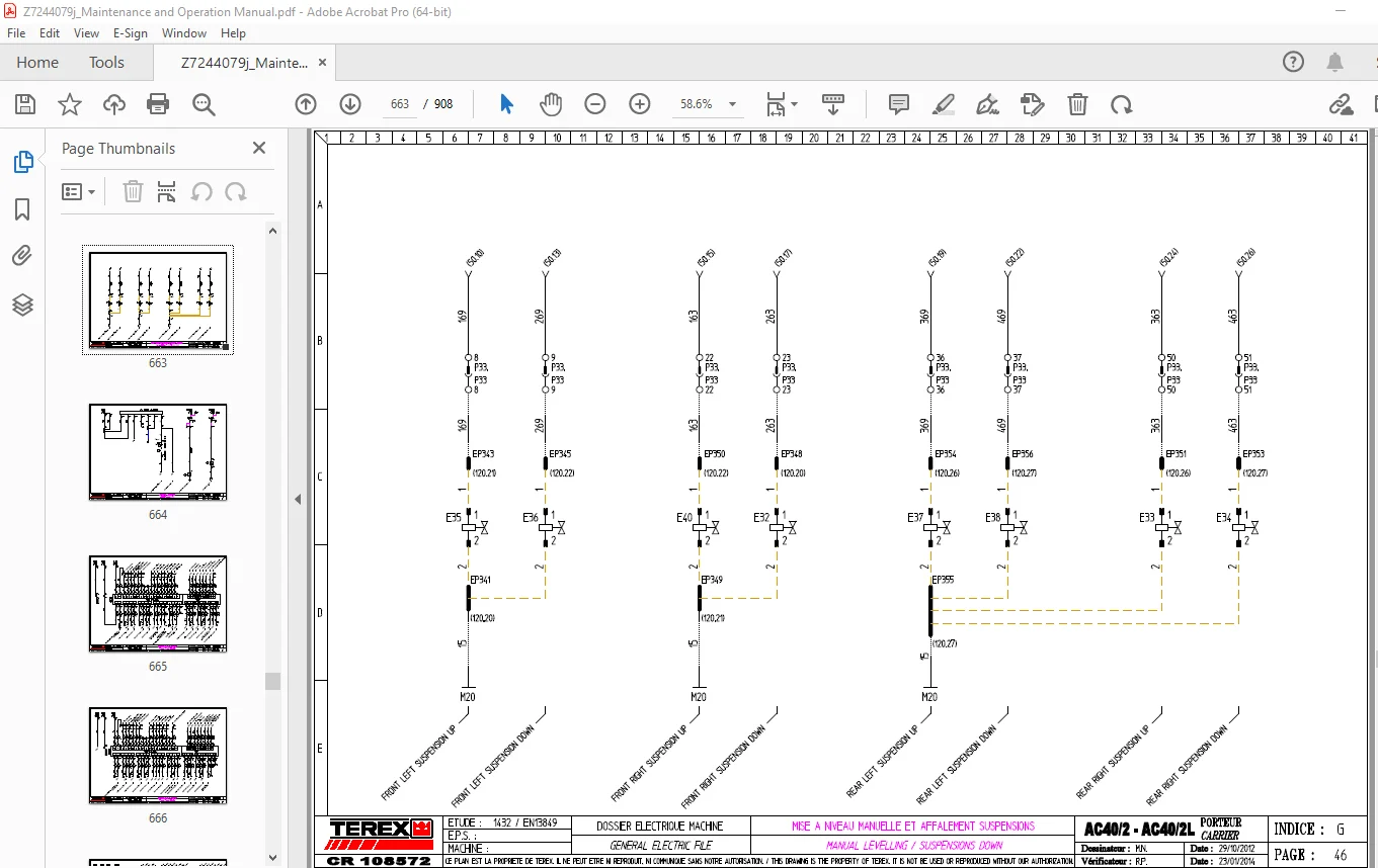
46 [G] MANUAL LEVELLING / SUSPENSIONS DOWN 663
47 [G] HEATER / AIR CONDITION 664
48 [G] Z10A AND Z10B CONTROLLERS 665
49 [G] Z11A AND Z11B CONTROLLERS 666
50 [G] Z12A AND Z12B CONTROLLERS 667
51 [G] Z13A LOGICAL RELAY 668
52 [G] CAN J1939 DISTRIBUTOR 669
53 [G] REAR LIGHTS 670
54 [G] Z10A AND Z10B LOGICAL RELAYS INPUTS / OUTPUTS 671
55 [G] Z11A AND Z11B LOGICAL RELAYS INPUTS / OUTPUTS 672
56 [G] Z11A AND Z11B LOGICAL RELAYS INPUTS / OUTPUTS 673
57 [G] Z12A AND Z12B LOGICAL RELAYS INPUTS / OUTPUTS 674
58 [G] Z13A LOGICAL RELAYS INPUTS / OUTPUTS 675
59 [G] SCR ELECTRONIC UNIT 676
60 [G] SCR CAN DISTRIBUTOR 677
61 [G] FUSES BEFORE IGNITION AND TURRET CAB GROUND 678
62 [G] TURRET CAB FUSES AFTER IGNITION 679
63 [G] 16 RELAYS BOARD 680
64 [G] MACHINES SELECTION CONNECTORS 681
65 [G] IGNITION / STARTING / ENGINE STOP 682
66 [G] GENERAL WARNING / HYDRAULIC OIL FILTER / GEARS / THROTTLE 683
67 [G] TRANSMISSION CONTROL / FRONT AXLE / REAR STEERING 684
68 [G] SUSPENSIONS/FRONT AXLE/INTER-WHEELS DIF /REAR STEERING 685
69 [G] OUTRIGGERS BEAMS AND PADS 686
70 [G] SLEWING LOCKING / COUNTERWEIGHT CONTROL 687
71 [G] AUXILIARY WINCH / ROTATION 688
72 [G] FLYGIB HOIST 689
73 [G] CRANE SAFETY FUNCTIONS 690
74 [G] FRONT WINDSCREEN WIPER / WORKING LIGHT 691
75 [G] WINDSCREEN WASHER / FAN / RADIO / CEILING LIGHT 692
76 [G] HORN / CIGAR LIGHTER / ROTATING BEACON / BOOM HEAD LIGHT 693
77 [G] HEATER 694
78 [G] HYDRAULIC OIL COOLER 695
79 [G] TELESCOP SELECTION / TELESCOP SENSORS 696
80 [G] SECURITIES OVERRIDE 697
81 [G] EXTERNAL OVERRIDE / LOCKED SUSPENSIONS 698
82 [G] CAN JOYSTICKS 699
83 [G] CRANE PROPORTIONNAL VALVES 700
84 [G] S L I / HEAD ELECTRONIC UNIT 701
85 [G] S L I / ARM ELECTRONIC UNIT 702
86 [G] BOOM CYLINDER PRESSURE SENSORS 703
87 [G] 4 AND 5 SECTIONS BOOM REEL DRUMS 704
88 [G] TELESCOPE OUT SAFETY SWITCH 705
89 [G] 4 AND 5 SECTIONS BOOM TELESCOP 706
90 [G] 3B6 BOOM ANEMOMETER / LIGHT / ANTI TWO BLOCK SENSORS 707
91 [G] Z1 LOGICAL RELAY 708
92 [G] Z1 LOGICAL RELAY INPUTS/OUTPUTS 709
100 [G] 710
101 [G] LOOMS FABRICATION MEAN FEATURES 711
102 [G] LOOMS FABRICATION MEAN FEATURES 712
103 [G] AC40 – AC60 TURRET CAB LOOM LAYOUT 713
104 [G] AC40 – AC60 TURRET CAB LOOM LAYOUT 714
105 [G] AC40 – AC60 TURRET CAB LOOM LAYOUT 715
106 [G] AC40 – AC60 TURRET CAB LOOM LAYOUT 716
107 [G] AC40 – AC60 TURRET CAB LOOM LAYOUT 717
108 [G] AC40 – AC60 TURRET CAB LOOM LAYOUT 718
109 [G] AC40 – AC60 TURRET CAB LOOM LAYOUT 719
110 [G] PROPORTIONAL VALVES LOOM LAYOUT 720
111 [G] AC/TC40 – 4 AND 5 SECTIONS BOOM LOOM LAYOUT 721
112 [G] AC/TC40 – 4 SECTIONS BOOM VALVES LOOM LAYOUT 722
113 [G] TURRET LOOM LAYOUT 723
114 [G] TURRET LOOM LAYOUT 724
115 [G] 3B6 S L I SENSORS LOOM LAYOUT 725
116 [G] SLEWING LOCKING SENSOR LOOM LAYOUT 726
117 [G] ENGINE LOOM LAYOUT 727
118 [G] ENGINE LOOM LAYOUT 728
119 [G] SLEWING SENSORS LOOM LAYOUT 729
120 [G] SUSPENSIONS LOOM LAYOUT 730
121 [G] CHASSIS LOOM LAYOUT 731
122 [G] CHASSIS LOOM LAYOUT 732
175 [G] CONNECTORS PART NUMBER OUT OF COMPONENTS 733
176 [G] CONNECTORS PART NUMBER OUT OF COMPONENTS 734
177 [G] CONNECTORS PART NUMBER OUT OF COMPONENTS 735
178 [G] CONNECTORS PART NUMBER OUT OF COMPONENTS 736
179 [G] CONNECTORS PART NUMBER OUT OF COMPONENTS 737
180 [G] CONNECTORS PART NUMBER OUT OF COMPONENTS 738
181 [G] CONNECTORS PART NUMBER OUT OF COMPONENTS 739
182 [G] CONNECTORS PART NUMBER OUT OF COMPONENTS 740
183 [G] CONNECTORS PART NUMBER OUT OF COMPONENTS 741
184 [G] CONNECTORS PART NUMBER OUT OF COMPONENTS 742
200 [G] BULBS PART NUMBER 743
300 [G] CARRIER CONNECTORS LOCATION 744
301 [G] CARRIER CONNECTORS LOCATION 745
302 [G] CARRIER CONNECTORS LOCATION 746
303 [G] CARRIER CONNECTORS LOCATION 747
304 [G] LIGHTING CONNECTORS LOCATION 748
305 [G] CARRIER CAB FUSES AND CONNECTORS LOCATION 749
306 [G] BR2 / 16 RELAYS BOARD 750
307 [G] BR3 / 16 RELAYS BOARD 751
308 [G] TURRET CONNECTORS LOCATION 752
309 [G] TURRET CAB FUSES LOCATION 753
310 [G] 16 RELAYS BOARD 754
S.V 08/24