Terex Crawler Crane HC 125 Parts Manual – PDF DOWNLOAD
$28.95
Terex Crawler Crane HC 125 Parts Manual – PDF DOWNLOAD
Description
Terex Crawler Crane HC 125 Parts Manual – PDF DOWNLOAD
FILE DETAILS:
Terex Crawler Crane HC 125 Parts Manual – PDF DOWNLOAD
Language : English
Pages : 337
Downloadable : Yes
File Type : PDF
IMAGES PREVIEW OF THE MANUAL:
TABLE OF CONTENTS:
Terex Crawler Crane HC 125 Parts Manual – PDF DOWNLOAD
DESCRIPTION
Main Hoist instaiiation – Front (1″ Rope)
Main Hoist AssemЫy – Front (1″ Rope)
Main Hoist AssemЫy – Rear (1″ Rope)
Clutch AssemЫy
Clutch Band AssemЫy
BrakeiPawi Assembly – Main Hoist
Rope Guard lnstallation, Front & Reai Diums
Fleeting Sheave lnstallation (3rd Drum)
А-2-В lnstallation – Offset Tip
(PL ONL У) А-2-В lnstallation, Wylie 150′ Мах. Jib
Load lndicator lnstl. – W1253L Single Line
Load lndicator lnstl. – W1253 Two Line
Wire Rope, Boom Line (3/4″ Rope)
Third Drum lnstallation
DESCRiPTiON
Single Swing lnstallation, lncluding Piping
Single Swing lnstallation, lncluding Piping (АС3966 & Later)
Swing Pinion Guard lnstl., (Single & DouЫe Swing)
Lube/Grease Piping – Single Swing
360 Deg. Swing Lock lnstallation
(PL ONL У) TurntaЫe Bearing lnstallation
TurntaЫe Bearing lnstallation Procedure
TurntaЫe Bearing lnstallation
DESCRIPT!ON
Carbody Transport Package AssemЫy
Vertical Jack AssemЫy
(PL ONL У) Shoe AssemЫy Service Кit – 38″ Shoe
(PL ONL У) Shoe AssemЫy Service Кit – 44″ Shoe
Crawler Shoe AssemЫy – (Stylized Drawing)
Crawler AssemЫy
Carbody AssemЫy
Sideframe AssemЫy, RH
Sideframe AssemЫy, LH
Drive TumЬier AssemЫy
Drive TumЫer AssemЫy
Gearbox & Motor AssemЫy Propel
ldler TumЫer AssemЫy
(PL ONL У) Tool Кit
(PL ONL У) Travel Package Handling List
Sideframe Counterweight lnstallation
Extended Axle AssemЫy, 59 НОТ
Boom Hoist Fixed Mast AssemЬiy (3/4;; Rope)
Boom Hoist Fixed Mast lnstallation (3/4″ Rope)
~hA;:ivA A.c:.c:Amhly
Gearbox & Motor AssemЫy, Boom Hoist
Floating Mast lnstallation (3/4″ Rope)
Floating ~Jlast AssemЫy (3/4 11 Rope)
Floating Mast Wear Pad lnstallation
Rope Wear Pad AssemЬ!y
Boom Outer AssemЫy, Offset Tip
Basic Pendant AssemЫy – Offset Boom Tip
Boom Deflector Sheave Support for 3 Lines
Boom Stop lnstallation
Boom Stop AssemЫy – 59″ Boom
Counterweight Handling Sheaves (1″ Rope)
Counterweight Sideframe Handling Sheaves for 3rd Drum (3/4″ Rope)
Ass’y .. & lnstl, 59Н Single Sheave Ext. (P/N 1186831-1.000″ Dia. Rope)
(P/N 1186848-1.125″ Dia. Rope)
Ass’y. & lnstl, 59Н Single Sheave Ext. (P/N 1186831-1.000″ Dia. Rope)
(P/N 1186848-1.125″ Dia. Rope)
59″ Boom Center Section
Pendant AssemЫy, 1 О Ft. 1.375 Dia. Pendant Set – Monolay
Pendant AssemЫy, 20 Ft. 1.375 Dia. Pendant Set – Monolay
Pendant AssemЫy, 40 Ft. 1.375 Dia. Pendant Set – Monolay
Mid Boom lnstallation
59Н Boom lnner AssemЫy
Jib Center, 1 О’ 7HL and 9HL
(PL ONL У) Jib 9HL, 40 Ft.
9HL and 15 Топ Jib AssemЫy (Stylized Drawing)
(PL ONL У) Jib Center, 20 Ft. 9HL with Pendant
Jib Center, 20 Ft. 9HL with Pendant
(PL ONL У) Pendant AssemЫy, 18′-10.5″ .875 Dia.
Pendant AssemЫy, Stylized Drawing
(PL ONL У) Jib Center, 1 О Ft. 9HL with Pendant
(PL ONLY) Pendant Link, Non-LMI lnstallation
Jib Backstay Pendant
Jib А-2-В lnstallation
Jib Backstay Pendant
Roller AssemЫy, lnstallation
DESCRIPTION
Power Train Ass’y. & lnstallation – Cummins МТ А-11-С245
Engine AssemЫy – Cummins МТ А-11-С245
Power Train Ass’y. & !nsta!!ation – Cummins МТА-11-С315
Engine AssemЫy – Cummins МТА-11-С315
Radiator/Fan Drive instaiiation (Cummins N-14)
Throttle AssemЫy
Quad Pump Drive
Radiator & Fan Drive lnstallation
Radiator Piping AssemЫy
Fuel Tank lnstallation
Fuei Tank AssemЬiy
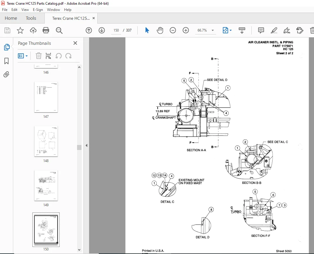
Air Cleaner lnstallation & Piping
(PL ONL У) Battery instaiiation & v·v,ring
(PL ONL У) Неаtег Piping instaliation
(PL ONL У) Fuei Piping instaiiation
lnstr. Sending Unit & Switch lnstallation
Power Train AssemЫy & lnstl. Cummins 6СТА 8.3-С240
Throttle AssemЫy
Engine Control AssemЫy
Charge Manifoid AssemЫy
lnstrument Sending Units & S\,.i1itches installation
Fuel Shutoff Wiring lnstallation
(PL ONL У) Radiator Piping AssemЫy
Air Cleaner lnstallation & Piping
Fuel Piping lnstallation for Cummins 6СТА 8.3-С240
Heater Piping for Cummins 6СТА 8.3-С240
Mag Pick-up lnstallation
Power Relay lnstallation
Fan Belt Guard lnstallation
Durst Gear Вох Remote Grease Piping AssemЫy
Radiator Fan Control Piping
Centerbase Weldment
Misc. Machine Deck Component lnstallation
(PL ONL У) Accident Prevention Sign lnstallation
Autolube Component lnstallation
ВuЬЫе Level lnstallation
51000 Lb. (WORKHORSE) Counterweight lnstallation
Upper Counterweight Weldment
Lower Counterweight WORKHORSE) AssemЫy
Counterweight Support AssemЫy & lnstallation
Counterweight Support Beam for 3′ Cylinder
Operator’s СаЬ Access Platform lnstallation
Operator’s СаЬ Access Platform
Right Hand Access P!atform !nstallation
Right Hand Access Platform Center
Right Hand Access Platform Rear
Left Hand Access Piatform instaiiation
Left Hand Access Platform Front
Code Plate lnstallation
Decal lnstallation
Lever Stand AssemЫy & lnstallation
Lever Stand AssemЫy
Left Hand Console AssemЫy
Right Hand Console AssemЬ!y
Hoist Brake Stand AssemЫy
Gauge Stand Weldment
LMI Base Weldment
Gauge Panel AssemЫy
Machineiy СаЬ LH lnstallation
Machiner; СаЬ, LH
LH Back Wall lnstallation
Machinery СаЬ RH lnstallation
Machinery СаЬ, RH
1 11 1 uavn. vv а11 111.:)LQIIQLIVI 1
LH Console lnstrument AssemЫy
RH Console lnstrument AssemЫy
LMi & DTi Stand AssemЫy
LMI & DTI AssemЫy (РАТ)
Lever Stand AssemЫy & lnstallation (РАТ)
Lever Stand AssemЫy (РАТ)
Air Conditioning for Operator’s СаЬ
Air Conditioning for Operator’s СаЬ for 6 СТ 8.3 Cummins Engine
DESCRIPTION
Electrical Schematic, Sheets 1-1 О
Electrical Schematic, (W/0 Workhorse) Sheets 1-8
Machinery Base Electrical
Counterweight Control Panel AssemЫy
Operator СаЬ lnstrument lnstallation – Electrical
Electrica! Control Panel AssemЫy
Wiring Harness, RH Machine Base
Lower Hydraulic Control
Limit Switch lnstallation, Mast
Operator СаЬ lnstrumentation lnstallation – Electrical (РАТ)
Electrical Clamshell Schematic
DESCR!PT!ON
Hydraulic Piping, Operator Platform
Auto Lube Piping – Upper
Hydraulic Piping – Single Swing
Hydraulic Piping – Single Swing (АС3966 & Later)
Lube/Grease Piping – Single Swing (АС3966 & Later)
Hydraulic Tank AssemЫy
Hydraulic Tank SubassemЫy
Operator’s СаЬ lnstrumentation lnstl., Hydraulic
Hydraulic Piping, RH Side
Hydraulic Piping, LH Side
Hydraulic Piping (WORKHORSE) Counterweight
Hydraulic Piping, 3rd Drum LH
Hydraulic Piping lnstallation, 3rd Drum
Hydraulic Piping, Transport Carbody
Transport Piping, Center Base
Hydraulic Piping, Engine Area
Hydraulic Piping, Center Deck
Hydraulic Schematics (Sheets 1-8)
Hydraulic Cooler AssemЫy
Hydraulic Pump Control AssemЫy
Hydraulic Clamshell Schematic
S.V 07/24