Terex Demag Crane CC 2500-1 Operator’s Manual – PDF DOWNLOAD
$31.95
Terex Demag Crane CC 2500-1 Operator’s Manual – PDF DOWNLOAD
Description
Terex Demag Crane CC 2500-1 Operator’s Manual – PDF DOWNLOAD
FILE DETAILS:
Terex Demag Crane CC 2500-1 Operator’s Manual – PDF DOWNLOAD
Language : English
Pages : 634
Downloadable : Yes
File Type : PDF
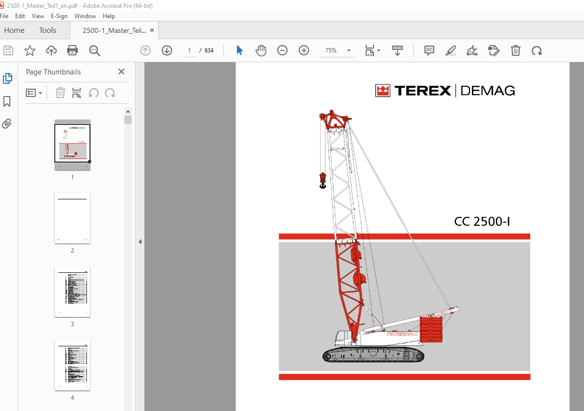
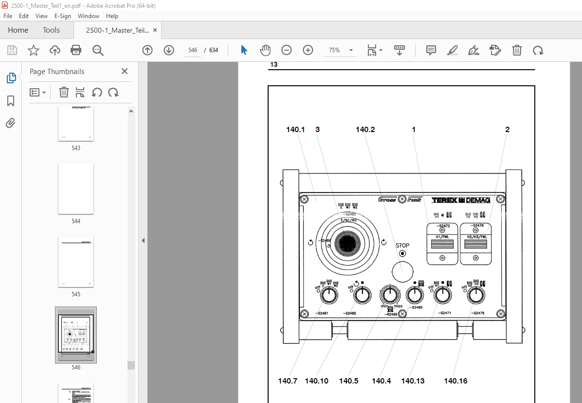
IMAGES PREVIEW OF THE MANUAL:
TABLE OF CONTENTS:
Terex Demag Crane CC 2500-1 Operator’s Manual – PDF DOWNLOAD
Foreword 1
1 Safety Instructions 3
1 1 General 3
1 2 Intended Use 5
1 3 Operating Conditions and Computed Design of the Crane 9
1 3 1 General 9
1 3 2 Classification of the Crane 9
1 3 3 Classification of the Engines 11
1 3 4 Workplace Ergonomics 13
1 3 5 Load and Utilisation of the Crane 15
1 3 6 Required Ambient Conditions 17
1 3 7 Service Life 19
1 3 8 Standards and Calculation Regulations 21
1 3 9 Dangers to Air Traffic 23
1 4 Safety Regulations 25
1 4 1 Organisational Measures 27
1 4 2 Personnel Selection and Qualifications 29
1 4 3 Particular Hazards 31
1 4 3 1 Electrical Energy 31
1 4 3 2 Gas, Dust, Steam, Smoke 39
1 4 3 3 Crushing / Collision 39
1 4 3 4 Snagging / Dragging 39
1 4 3 5 Crushing / Shearing 41
1 4 3 6 Danger Due to Slipping, Tripping, Falling 41
1 4 4 Combination of Hazards with Combined Operation of Two or More Cranes
43
1 4 4 1 Operating Areas of Several Cranes Overlap 43
1 4 4 2 Several Cranes Raising a Load Together 45
1 4 5 Before Crane Operation 47
1 4 6 During Operation of the Crane 51
1 4 7 Following Crane Operation 61
1 4 8 When Assembling and Dismantling Crane Components 63
1 5 Hand Signals 67
1 5 1 General Hand Signals 69
1 5 2 Hand Signals for Working Movements 71
1 5 3 Hand Signals for Driving Movements 73
1 6 Power Supply Failure 75
Index
059–1000 2
2 Structure of the Crawler–mounted Crane 3
2 1 Overview 3
2 2 Superstructure 5
2 3 Undercarriage 7
2 4 Counterweight Vehicle 250 t (551 2 kip) 9
2 5 Boom Variants 11
2 6 Technical Description 15
2 6 1 Chassis 15
2 6 2 Superstructure 15
2 6 3 Additional Equipment (Options) 17
2 6 4 Hook Block 17
2 6 5 Technical Data 19
2 6 6 Hydraulic Pumps 23
2 7 Safety–Relevant Components 25
2 7 1 Ladders and Catwalks 25
2 7 2 Headlights 27
2 7 3 Emergency Exit 27
2 8 Signs and Symbols 29
2 8 1 Signs in the Crane Operator’s Cab 29
2 8 2 Signs and Symbols on the Superstructure 35
2 8 3 CE Safety Signs 39
2 8 4 Safety Signs (USA Only) 45
3 —
4 Crane Operator’s Cab 3
4 1 Operating Elements in the Crane Cab 3
4 2 Control Lever 5
4 3 Add–on Console 13
4 3 1 General Arrangement of Assembly Consoles 13
4 3 2 Display and Operating Elements on the Add–on Consoles 15
4 3 3 Display and Control Console LLD System 19
4 3 4 Display and Operating Console for Monitoring of Engine 21
4 4 Side Panel 33
4 5 Side Panel, Seat Bracket 35
4 6 Radio Remote Control 37
4 7 Mobile Control Panel for Emergency Control 39
4 8 Warning Light (Required Version in the European Union) 43
4 9 Warning Light (Required Version in Several Countries
Outside of the European Union) 45
4 10 Entering / Leaving the Cab 47
4 11 Warning Light (National Regulations or Optional) 47
4 12 Tilting the Cab 49
4 13 Adjustment of the Crane Operator’s Seat 51
4 14 Charging the Batteries 53
Index
059–1000 3
5 Engine and Drive 3
5 1 Engine Control 5
5 2 Starting 7
5 2 1 Before Starting 7
5 2 2 Starting Procedure 9
5 2 3 Starting Aid 11
5 2 3 1 External Start with jumper cables 11
5 2 3 2 External Starting With the Integrated Socket 13
5 2 4 To be Observed Following Starting 15
5 2 5 Warming up the Hydraulic System 17
5 2 6 Warming–up Procedure 17
5 2 7 Checks With the Diesel Engine Running 19
5 2 8 Instructions for Operation 21
5 2 9 Switching Off 21
5 2 10 Shutting Down With Quick Stop Fitting (Optional) 23
5 3 Automotive Driving 25
5 4 Load Limit Sensing Control 25
6 Driving the Crawler–mounted Crane 3
6 1 General Instructions 3
6 1 1 Main Driving Direction 3
6 1 2 Requirements for Road Surface Conditions 5
6 1 3 Regulations for Driving Operation 5
6 2 Controlling the Undercarriage 9
6 2 1 Control Movements 9
6 2 2 Control Movements for Tailing Operation 9
6 2 3 Options for Controlling the Driving Speed 11
6 3 Driving without Load on the Horizontal and Angled Road
Surface 15
6 3 1 General Instructions 15
6 3 2 Driving without Load 17
6 4 Driving with Load on a Horizontal and Graded Road Surface 19
6 4 1 General Instructions 19
6 4 2 Driving With Load on Horizontal, Even Terrain
(± 0 3° Slope) 21
6 4 3 Driving With Load on Inclined, Even Territory
(> 0 3° Incline) 25
7 Slewing and Braking the Superstructure 3
7 1 Speed Control 3
7 2 Slewing 5
7 3 Braking the Superstructure 7
7 4 Mechanical Locking of the Holding Brake in Opened Position 9
Index
059–1000 4
8 Operating the Safety Equipment 3
8 1 IC–1 Crane Control 3
8 1 1 Load Limit Device (LLD) 5
8 1 1 1 Function 5
8 1 1 2 Bridging the Load Limit Device 13
8 1 1 3 LLD Error Code Table 17
8 1 2 Description of the monitor screens and function keys 37
8 1 2 1 Opening Screen 37
8 1 2 2 Symbols “Main Menu of the Display and Operating Console of
the LLD system” (LLD Screen) 37
8 1 2 3 Symbol “Main Menu of the Display and Operating Console of
the Engine and Crane Operating System” (MOT Screen) 39
8 1 2 4 “System Settings” Screen 43
8 1 2 5 “Set Crane Type” Screen 43
8 1 2 6 “Set Display” Screen 45
8 1 2 7 “LLD” Screen 47
8 1 2 8 “MOT” Screen 57
8 1 3 Operating the LLD System 59
8 1 3 1 Switching on 59
8 1 3 2 Entering the Operating Mode 61
8 1 3 3 Setting the Configuration Programs for Crane Assembly 69
8 1 3 4 Configuration Operation 75
8 1 4 “View Table” Screen 77
8 1 5 “Operating Range Limit” Screen 81
8 1 5 1 Switching on 81
8 1 5 2 Setting up the Various Limits 83
8 1 6 Display of the Ground Pressure 89
8 1 7 Logger (optional) 91
8 1 7 1 Calling up the Screens 91
8 1 8 “Data Logger” Screen (Data Recorder) 93
8 1 9 “Wind Logger” Screen 99
8 1 9 1 Read Out Log Files 103
8 1 10 “Parameters” Screen 107
8 1 11 Load Monitoring Assembly 121
8 1 12 Gradient and Slewing Angle Display 123
8 1 13 Troubleshooting 125
8 1 13 1 “Error Messages” Screen 127
8 1 14 “CAN” Screen 131
8 1 15 “I/O” Screen 133
8 1 16 “Function Diagnostics” Screen 135
8 1 17 Malfunction Procedure 137
8 1 17 1 Error–Free Operation / Malfunction 137
8 1 17 2 Failure of the Crane Control (CAN Stop) 137
8 1 17 3 Failure of a Monitor 137
8 2 Limit Switches 139
8 2 1 Hoist Limit Switch 139
8 2 2 Lower Limit Switch 143
8 3 Dead Man’s Handle Activation 145
Index
059–1000 5
9 Working With the Crane Equipment 3
9 1 Preparations 3
9 1 1 Positioning the Crane 3
9 1 2 Working Instructions 9
9 1 3 Wind Speeds — Dynamic Pressure 9
9 1 3 1 Permitted Wind Speeds with Crane Operation 11
9 2 Selection of the Functions for Crane Operation 17
9 2 1 Allocation of the Control Levers 17
9 2 2 Selection of Functions 19
9 3 Configuring the Crane Equipment 21
9 3 1 Simultaneous Operation of Derricking Gear (E) and
Luffing Gear 1 (W1) 21
9 3 2 Simultaneous Operation of Derricking Gear (E) and
Luffing Gear (W2) 21
9 3 3 Simultaneous Operation of Luffing Gear 1 (W1) and
Luffing Gear 2 (W2) 23
9 4 Operating the Reeving Winch 25
9 4 1 General Instructions 25
9 4 2 Operation 25
9 5 Crane Operation 27
9 5 1 Winch Selection for Crane Operation 27
9 5 1 1 Operating the Derricking Gear (E) 27
9 5 1 2 Simultaneous Operation of Derricking Gear (E) and
Hoist 1 (H1) 27
9 5 1 3 Operating Range of the Main Boom 27
9 5 2 Luffing Gear 1 (W1) Operation 29
9 5 2 1 Simultaneous Operation of Luffing Gear 1 (W1) and
Hoist 2 (H2) 29
9 5 2 2 Operating Range of the Fly Jib 29
9 5 2 3 Luffing Gear 1 as Hoist 3 (Optional) 29
9 5 3 Operation of the Luffing Gear 2 (W2) 31
9 5 3 1 Simultaneous Operation of Luffing Gear 2 (W2) and
Hoist Gear 1 (H1) 31
9 5 3 2 Operating Range of the Main Boom 31
9 5 4 Crane Operation with Double Hook Block, Hoist 1 and
Hoist 2 in Combined Operation 33
9 5 4 1 Preparing for Operation 33
9 5 4 2 Operation at Normal Speed 37
9 5 4 3 Operation at High Speed 37
9 5 5 Operation with 2 Reeved Hook Blocks 41
Index
059–1000 6
10 Working With the Superlift 3
10 1 Description of the Superlift 3
10 2 Modus Operandi 5
10 3 Safety Instructions for Working with the Superlift 7
10 4 Crane Work Without Superlift Counterweight (SL CWT) 11
10 5 Operating the Crane with the Superlift Counterweight 13
10 5 1 With Standard Superlift Equipment 13
10 5 2 With Vario SL Equipment 23
10 5 3 With Telescoping Superlift Equipment 43
11 Operating the Heating and Ventilation 3
11 1 Operating the Heating 3
11 1 1 Controls 5
11 2 Heating Operation 7
11 2 1 Setting the Timer 7
11 2 2 Heating Operation Without Preselection With Ignition “OFF” 9
11 2 3 Heating Operation Without Preselection With Ignition “ON” 11
11 2 4 Heating Operation With Preselection 13
11 2 5 Safety Equipment 17
11 3 Operating the Air Conditioning System 19
11 3 1 Controls 19
12 Parking the Crane 3
12 1 Wind Speeds 3
12 2 Lowering the Boom System 7
13 Emergency Operation 3
13 1 Emergency Control System with the Mobile Control Panel 3
Index
059–1000 7
14 Radio Remote Control 3
14 1 General 3
14 2 Preparations for Assembly Using the Radio Remote Control 3
14 3 Tabular Collation of the Assembly Procedures 7
14 3 1 Assembly Procedures on the Superstructure 7
14 3 2 Assembly Procedures on the Chassis 7
14 3 3 Assembly Procedures on the Counterweight Dolly 9
14 4 Assembly Procedures in Case of Radio Remote Control Failure 11
14 4 1 Virtual Radio Remote Control 11
14 4 2 Manual Control of Assembly Procedures 13
14 5 Tabular Collation of the Assembly Procedures in Case of Radio Remote
Control Failure 15
14 5 1 Assembly Procedures on the Superstructure 15
14 5 2 Assembly Procedures on the Chassis (UW) 15
14 5 3 Assembly Procedures on the Counterweight Dolly (GW) 17
15 —
16 Driving With the Counterweight Dolly 3
16 1 General 3
16 2 Radio Remote Control 9
16 3 Description of Mechanics 11
16 3 1 Basic Position and Angle Functions 11
16 3 2 Reversing (Definition) 11
16 4 Description of Software 13
16 4 1 Counterweight Dolly Menu 13
16 5 Setting the Operating Modes 15
16 5 1 Selection “Operation With Counterweight Dolly” (CWT Dolly) 15
16 5 2 Selection of the “Counterweight Dolly” (CWT Dolly) Menu 17
16 5 3 Procedure when Changing Operating Mode 19
16 5 4 Shutoff criteria 19
16 5 5 Operating Mode “Rear Travel” 21
16 5 6 Operating Mode “Circular Travel” 27
16 5 7 Operating Mode “Parallel Travel” 29
16 5 8 Changing the Swivelling Bolster Positions 33
16 5 9 Leaving the Operating Mode “Counterweight Dolly” 35
16 5 10 Parking the Counterweight Vehicle 35
059–1000 8
20 Working With the Superlift 3
20 1 General 3
20 2 Modus Operandi 5
20 3 Safety Instructions for Working With Superlift Equipment With
Counterweight Dolly 7
20 4 Requirement Regarding the Ground Conditions at the Operating
Site 11
20 5 Operating the Crane Without the Superlift CounterWeight 13
20 6 Operating the Crane With the Superlift Counterweight 15
20 6 1 With Variable Superlift Equipment 15
20 6 1 1 Preparations for Raising a Load 15
20 6 1 2 Adjusting the Superlift Counterweight Radius (SCR) 17
20 6 1 3 Entering the Operating Mode 21
20 6 1 4 Raising the Load 23
20 6 1 5 Setting the Load Down 27
S.V 07/24