The motor vehicle Manual by Tk GarretThe motor vehicle Manual by Tk Garret
DESCRIPTION:
The motor vehicle Manual by Tk Garret – PDF DOWNLOAD
Because of the continuing phenomenally rapid rate of progress in automotive technology, the revision for this the thirteenth edition of The Motor Vehicle has been on a major scale.
No fewer than seven new chapters have been created. Of these, three are entirely new, while the remaining four comprise mainly new material that could not have been accommodated in existing chapters without making them too long and cumbersome.
Of the entirely new chapters, one is on electric propulsion which, owing to pressure of legislation is now beginning to be taken seriously by the industry. It covers all the alternatives, from conventional lead-acid, and other, battery-powered vehicles to fuel cells and hybrid power units.
A second covers both static and dynamic safety which, again because of pressure of legislation, is a field in which enormous progress has been made. This progress, which embraces almost all aspects of automotive design, has become possible largely because of the development of computer aided control. The third of these entirely new chapters deals with wheels and tyres.
Over the past few decades, wheels and especially tyres have moved on, from being simply components that the designer chose largely on the basis of dimensional and commercial considerations, to becoming an integral part of the tuned suspension system. In the twelfth edition, only one chapter was devoted to the compression ignition engine.
Now, owing to a major extent to the widespread application of diesel power to cars and light commercial vehicles, so much new equipment has been developed that it has now been expanded into three chapters.
One of these comprises mainly the original subject matter, while the other two contain a considerable amount of new information on aspects such as common rail injection, recently developed distributor type pumps, and electronic control of injection. Two chapters now cover automatic, semi-automatic and continuously variable transmissions.
These contain some of the original material but also information on the Porsche Tiptronic and Alfa Romeo Selespeed semi-automatic transmissions, the latter being basically the Magneti Marelli system. Chapter 39 has been added to contain much of the original material on anti-lock brakes together with new information on some of the latest developments for improving stability by means of computer aided control over both braking and traction.
In the next chapter, a significant amount of space is devoted to both the basic considerations and the practice of electrically actuated powerassisted steering, which now looks set ultimately to render hydraulic power assistance systems redundant.
TABLE OF CONTENTS:
The motor vehicle Manual by Tk Garret – PDF DOWNLOAD
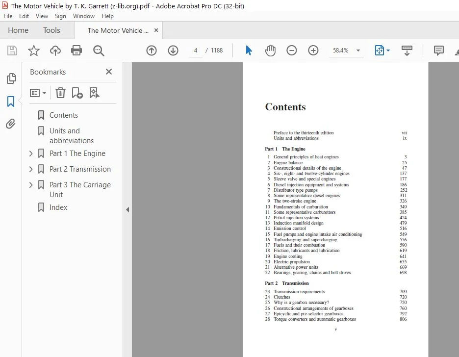
Contents...............................................................................   4
Units and abbreviations................................................................   8
Part 1 The Engine......................................................................  10
	1 General principles of heat engines...............................................  12
		1.1 Heat and work..............................................................  12
		1.2 Work.......................................................................  13
		1.3 Joule's equivalent.........................................................  13
		1.4 Thermal efficiency.........................................................  13
		1.5 Calorific value............................................................  13
		1.6 Power......................................................................  14
		1.7 General method of conversion of heat to work...............................  14
		1.8 Practical form of working vessel...........................................  15
		1.9 Rotary and reciprocating engines...........................................  15
		1.10 Cylinder, piston, connecting rod and crankshaft...........................  16
		1.11 Method of working.........................................................  17
		1.12 The four-stroke cycle.....................................................  17
		1.13 Heat balance..............................................................  19
		1.14 Factors governing the mean effective pressure.............................  21
		1.15 Work per minute, power and horsepower.....................................  22
		1.16 Piston speed and the RAC rating...........................................  23
		1.17 Indicated and brake power.................................................  23
		1.18 Mechanical efficiency.....................................................  24
		1.19 Limiting factors..........................................................  24
		1.20 Characteristic speed power curves.........................................  25
		1.21 Torque curve..............................................................  27
		1.22 Effect of supercharging on bmep and power.................................  28
		1.23 Brake specific fuel consumption...........................................  30
		1.24 Commercial rating.........................................................  32
		1.25 Number and diameter of cylinders..........................................  32
		1.26 Power per litre...........................................................  32
		1.27 Considerations of balance and uniformity of torque........................  33
	2 Engine balance...................................................................  34
		2.1 Practical balancing........................................................  35
		2.2 Balance of reciprocating parts.............................................  36
		2.3 Other V twin engines.......................................................  38
		2.4 Horizontally-opposed twin..................................................  38
		2.5 Side-by-side twin with cranks at 180.......................................  38
		2.6 Four-cylinder in-line engine...............................................  39
		2.7 General method of balancing................................................  39
		2.8 Couples due to revolving masses............................................  40
		2.9 Balanced throws............................................................  40
		2.10 Torsional vibration.......................................................  40
		2.11 Secondary forces and couples..............................................  40
		2.12 Effect of short connecting rod............................................  41
		2.13 Firing intervals..........................................................  43
		2.14 Compactness of engine.....................................................  43
		2.15 Harmonic balancer.........................................................  43
		2.16 Torsional disturbances....................................................  44
		2.17 In-line engines with three cylinders......................................  45
		2.18 Engines with five cylinders...............................................  46
		2.19 Flexible mountings........................................................  46
		2.20 Modes of vibration, natural frequency, forcing frequency and resonance....  47
		2.21 Principal axes of inertia.................................................  48
		2.22 Importance in the design of engine mountings..............................  48
		2.23 Hydraulically damped engine mountings.....................................  51
		2.24 The Avon Hydramount.......................................................  54
	3 Constructional details of the engine.............................................  56
		3.1 General engine parts.......................................................  56
		3.2 The piston.................................................................  56
		3.3 Thermal considerations.....................................................  57
		3.4 Design details.............................................................  57
		3.5 Slipper and articulated pistons............................................  61
		3.6 AEconoglide piston.........................................................  61
		3.7 Combustion chamber in piston...............................................  62
		3.8 Piston rings...............................................................  64
		3.9 Ring sections..............................................................  64
		3.10 Oil control rings.........................................................  65
		3.11 Ring belt design..........................................................  67
		3.12 Cylinder bore wear and corrosion..........................................  68
		3.13 Gudgeon pin...............................................................  69
		3.14 Connecting rods...........................................................  69
		3.15 Typical connecting rods...................................................  70
		3.16 Bearing bushes............................................................  72
		3.17 Bearing materials.........................................................  72
		3.18 Thin-wall bearings........................................................  72
		3.19 Stronger materials........................................................  74
		3.20 Corrosion of bearings.....................................................  74
		3.21 Aluminium-tin bearing alloys..............................................  74
		3.22 Aluminium-silicon and aluminium-tin-silicon alloys........................  75
		3.23 The crankshaft............................................................  75
		3.24 Crankshaft materials......................................................  76
		3.25 Built-up crankshafts......................................................  79
		3.26 Surface-hardening of shafts...............................................  80
		3.27 Chill casting.............................................................  81
		3.28 High-frequency induction hardening: flame hardening.......................  81
		3.29 The poppet valve..........................................................  82
		3.30 The valve in practice.....................................................  83
		3.31 Coated valves.............................................................  84
		3.32 Corrosion and wear........................................................  84
		3.33 Valve rotation............................................................  85
		3.34 Seat inserts in cylinder heads............................................  85
		3.35 Layout of valves and form of combustion chamber...........................  86
		3.36 Variable valve timing (VVT)...............................................  89
		3.37 Advantages of VVT.........................................................  90
		3.38 Early inlet valve closure (EIVC)..........................................  90
		3.39 Problems associated with EIVC.............................................  91
		3.40 Late inlet valve closure (LIVC)...........................................  91
		3.41 Variable valve timing and the Atkinson cycle..............................  92
		3.42 Some simple VVT mechanisms................................................  92
		3.43 VPC, VLTC, VPLC and VET systems...........................................  92
		3.44 The MechadyneÒMitchell system.............................................  95
		3.45 Control of the Mechadyne–Mitchell system..................................  98
		3.46 Multi-valve heads.........................................................  99
		3.47 Cylinder head Ò some overall design considerations........................ 101
		3.48 An interesting cylinder head design....................................... 103
		3.49 Cylinder block and crankcase arrangement.................................. 106
		3.50 The aluminium crankcase................................................... 107
		3.51 Camshaft drive............................................................ 110
	4 Six-, eight- and twelve- cylinder engines........................................ 114
		4.1 Six cylinders.............................................................. 114
		4.2 Dynamic balance............................................................ 115
		4.3 Firing order............................................................... 115
		4.4 Eight cylinders............................................................ 115
		4.5 Firing order............................................................... 116
		4.6 Balanced webs and torsional oscillation.................................... 117
		4.7 Difficulties met in design................................................. 118
		4.8 Humber Super Snipe engine.................................................. 118
		4.9 Jaguar AJ6 engine.......................................................... 122
		4.10 Rover 2.3/2.6-litre E series engines...................................... 126
		4.11 Ford V-six range.......................................................... 129
		4.12 Mercedes M112 V6 engines.................................................. 130
		4.13 The main castings of the Mercedes engine.................................. 133
		4.14 Valves and combustion system.............................................. 135
		4.15 Meeting future emissions regulations...................................... 136
		4.16 Dual ignition and low fuel consumption.................................... 139
		4.17 Inlet and exhaust manifolds............................................... 141
		4.18 The ASSYST maintenance system............................................. 142
		4.19 The V-eight............................................................... 142
		4.20 Balance and firing intervals of V-eight................................... 143
		4.21 Secondary balance with two-plane shaft.................................... 144
		4.22 Construction of V-eight................................................... 144
		4.23 A British V-eight engine.................................................. 145
		4.24 Jaguar 5.3-litre V-twelve................................................. 148
		4.25 Jaguar with May Fireball combustion chamber............................... 151
	5 Sleeve- valve and special engines................................................ 154
		5.1 Burt single-sleeve valve................................................... 154
		5.2 Arrangement of ports....................................................... 155
		5.3 Advantages and disadvantages of sleeve valves.............................. 156
		5.4 Rotary valve............................................................... 156
		5.5 Cross rotary-valve engine.................................................. 157
		5.6 Aspin engine............................................................... 158
		5.7 NSU Wankel rotary engine................................................... 158
	6 Diesel injection equipment and systems........................................... 163
		6.1 Ignition by the temperature of compression................................. 163
		6.2 Air blast injection........................................................ 164
		6.3 Mechanical injection....................................................... 165
		6.4 Power : weight ratio....................................................... 166
		6.5 Injection and combustion processes......................................... 166
		6.6 Three phases of combustion................................................. 166
		6.7 Delay period............................................................... 167
		6.8 Second phase............................................................... 167
		6.9 Final phase of combustion.................................................. 168
		6.10 Types of combustion chamber............................................... 168
		6.11 Direct injection.......................................................... 168
		6.12 Pre-combustion chamber.................................................... 169
		6.13 Controlled air swirl...................................................... 170
		6.14 Comet swirl chamber....................................................... 170
		6.15 Suarer dual-turbulence system............................................. 170
		6.16 Evolution of the Perkins range of diesel engines.......................... 171
		6.17 The Phaser combustion chamber............................................. 171
		6.18 Injection equipment....................................................... 175
		6.19 Pintle type nozzle........................................................ 177
		6.20 Pintaux nozzle............................................................ 178
		6.21 Hole type nozzles......................................................... 178
		6.22 Injector assemblies....................................................... 180
		6.23 Injectors for small diesel engines and two-stage injection................ 180
		6.24 Stanadyne Pencil injector................................................. 182
		6.25 Injection control......................................................... 184
		6.26 Bosch snubber valve....................................................... 185
		6.27 Types of injection pump................................................... 185
		6.28 The Lucas CAV injection pumps............................................. 186
		6.29 Details of the Minimec pump............................................... 186
		6.30 Minimec pumping elements.................................................. 189
		6.31 Starting from cold........................................................ 190
		6.32 Governors................................................................. 192
		6.33 Injection advance......................................................... 194
		6.34 General principles of engine speed control................................ 194
		6.35 Types of governor......................................................... 195
		6.36 Types of governor mechanism............................................... 195
		6.37 Torque control............................................................ 196
		6.38 The mechanical governor fitted to the Minimec pump........................ 197
		6.39 Bosch mechanically governed in-line pump.................................. 201
		6.40 Bosch electronic controls for injection pumps............................. 202
		6.41 Unit injection............................................................ 204
		6.42 Lucas electronic unit injection (EUI) system.............................. 206
		6.43 Penske/Detroit Diesel electronic unit injection........................... 209
		6.44 The Cummins PT system..................................................... 210
		6.45 The GM unit injection system.............................................. 216
		6.46 Common rail injection systems............................................. 218
		6.47 The Bosch system.......................................................... 219
		6.48 Components of the Bosch system............................................ 220
		6.49 Injectors................................................................. 221
		6.50 Diesel fuel filtration in general......................................... 225
		6.51 Filtration and system layouts............................................. 226
	7 Distributor type pumps........................................................... 229
		7.1 Lucas DP series distributor type pumps..................................... 229
		7.2 Lucas DPA type pump........................................................ 229
		7.3 DPA pump governor.......................................................... 233
		7.4 Lucas DPS pump............................................................. 234
		7.5 DPS fuel supply and distribution system.................................... 236
		7.6 Engine starting............................................................ 238
		7.7 Control of maximum fuel delivery........................................... 239
		7.8 The two speed governor..................................................... 241
		7.9 Scroll plates.............................................................. 242
		7.10 Boost control............................................................. 243
		7.11 Automatic advance and retard unit......................................... 243
		7.12 Lucas DPC pump............................................................ 245
		7.13 Excess fuel............................................................... 248
		7.14 Injection timing advance and retard....................................... 248
		7.15 Low load advance, external control........................................ 252
		7.16 DPC boost controller...................................................... 255
		7.17 Electronic control of distributor pumps................................... 257
		7.18 The Lucas EPIC electronically controlled pump............................. 258
		7.19 The electronic control system............................................. 259
		7.20 The Bosch systems......................................................... 261
		7.21 Governing the VE pump..................................................... 265
		7.22 Torque control for the VE type pump....................................... 267
		7.23 Boost pressure and altitude compensation modules.......................... 269
		7.24 Load dependent injection timing........................................... 270
		7.25 Cold start advance and stopping the engine................................ 271
		7.26 Bosch VP44 radial plunger type pump....................................... 273
		7.27 The incremental pressure stages........................................... 275
		7.28 Control over injection quantity per shot.................................. 276
		7.29 Fuel delivery and distribution............................................ 277
		7.30 Control over injection quantity and timing................................ 278
		7.31 The angular encoder....................................................... 279
		7.32 Stanadyne rotary distributor pumps........................................ 281
		7.33 Stanadyne DS electronically controlled pump............................... 285
	8 Some representative diesel engines............................................... 288
		8.1 Perkins P3 diesel engine................................................... 288
		8.2 Perkins Prima DI engine.................................................... 290
		8.3 Gardner LW................................................................. 293
		8.4 Cummins 10-litre diesel.................................................... 296
		8.5 Relative merits of spark ignition and ci engines........................... 300
	9 The two- stroke engine........................................................... 303
		9.1 Three-port two-stroke engine............................................... 304
		9.2 Reverse-flow scavenge DKW engine........................................... 306
		9.3 Special constructions of two-stroke engine................................. 307
		9.4 Separate phased pump....................................................... 307
		9.5 Trojan engine.............................................................. 308
		9.6 Kadenacy system............................................................ 310
		9.7 Loop scavenge, Schnuerle system............................................ 312
		9.8 Exhaust pulse charging..................................................... 312
		9.9 Uniflow scavenging: opposed-piston engines................................. 312
		9.10 Compression-ignition two-stroke engine.................................... 312
		9.11 GM diesel with rotary blower and poppet exhaust valves.................... 313
		9.12 Foden six-cylinder two-stroke ci engine................................... 313
		9.13 Blower and scavenging..................................................... 317
		9.14 Crankshaft balance and firing order....................................... 317
		9.15 GM two-stroke diesel...................................................... 318
		9.16 Opposed-piston engine..................................................... 320
		9.17 Comparison of advantages.................................................. 323
	10 Fundamentals of carburation..................................................... 326
		10.1 The basic requirements.................................................... 327
		10.2 Requirements for metering and mixing...................................... 327
		10.3 Mixture quality........................................................... 328
		10.4 Induction of the mixture.................................................. 329
		10.5 Volumetric efficiency..................................................... 330
		10.6 Throttling................................................................ 331
		10.7 Fuel and air metering..................................................... 333
		10.8 Volume and mass flow...................................................... 334
		10.9 Fixed- and variable-choke carburettors.................................... 335
		10.10 The fixed-choke type..................................................... 335
		10.11 Fuel : air ratio compensation for fixed-choke carburettors............... 337
		10.12 Compensation by compound and submerged jets.............................. 338
		10.13 Air bleed compensation................................................... 340
		10.14 Multiple venturis intensify air bleed compensation....................... 342
		10.15 The Zenith V-type emulsion block......................................... 343
		10.16 Secondary suction effects................................................ 343
		10.17 Mixture requirements in more detail...................................... 343
		10.18 Principle of the intermediate chamber.................................... 345
		10.19 Starting and idling enrichment devices................................... 346
		10.20 Separate starting and warm-up enrichment devices......................... 347
		10.21 Zenith VE starter carburettor............................................ 348
		10.22 Thermostatic control for starting and warm-up............................ 349
		10.23 Solex progressive starter................................................ 350
		10.24 Idling systems and progression jets...................................... 352
		10.25 Requirements for acceleration............................................ 353
		10.26 Provision for acceleration............................................... 353
		10.27 Mechanically actuated acceleration pumps................................. 354
		10.28 Depression actuated acceleration pumps................................... 355
		10.29 Enrichment for maximum power............................................. 356
		10.30 Static power enrichment.................................................. 357
		10.31 Economiser devices....................................................... 361
	11 Some representative carburettors................................................ 362
		11.1 Venturi diameter.......................................................... 362
		11.2 Zenith W type carburettors................................................ 363
		11.3 Zenith IZ Carburettors.................................................... 365
		11.4 Zenith IV carburettors.................................................... 367
		11.5 Adaptation for emission control........................................... 368
		11.6 Multi-barrel carburettors................................................. 370
		11.7 A three-stage throttle mechanism.......................................... 372
		11.8 Solex MIMAT carburettor................................................... 373
		11.9 An electronically controlled four-barrel carburettor...................... 380
		11.10 Constant-depression carburettors......................................... 389
		11.11 SU constant-depression carburettor....................................... 391
		11.12 SU carburettor type HIF.................................................. 392
		11.13 Zenith-Stromberg CD and CDS carburettors................................. 394
		11.14 Zenith-Stromberg CDSE emission carburettor............................... 395
		11.15 Zenith-Stromberg CD4 and CD5 carburettors................................ 396
		11.16 Mixture ratio curves..................................................... 398
		11.17 Automatic governor....................................................... 399
	12 Petrol injection systems........................................................ 401
		12.1 Basic considerations...................................................... 402
		12.2 Injection system types and layouts........................................ 403
		12.3 Injection strategies...................................................... 404
		12.4 Injector design........................................................... 405
		12.5 Some other injectors...................................................... 408
		12.6 Start valves.............................................................. 410
		12.7 Air-flow metering......................................................... 410
		12.8 Suspended-plate-type flow sensor.......................................... 411
		12.9 Swinging-gate-type air flow sensor........................................ 413
		12.10 Mass-flow sensors........................................................ 414
		12.11 Lambda sensor............................................................ 415
		12.12 Bosch K-Jetronic system.................................................. 418
		12.13 The fuel distributor..................................................... 420
		12.14 Bosch KE-Jetronic system................................................. 421
		12.15 Bosch L-Jetronic system.................................................. 423
		12.16 Bosch LH-Jetronic system................................................. 426
		12.17 Bosch Motronic system.................................................... 427
		12.18 The electronic ignition control.......................................... 427
		12.19 Fuel supply.............................................................. 429
		12.20 Overall principle of operation........................................... 430
		12.21 Other variables.......................................................... 431
		12.22 The Weber electronic control system...................................... 435
		12.23 Bosch Mono-Jetronic system............................................... 435
		12.24 The GM Multec single-point system........................................ 437
		12.25 The Multec multi-point system............................................ 439
		12.26 Rover throttle body injection and ignition control....................... 440
		12.27 Ignition control......................................................... 443
		12.28 The air-intake system.................................................... 444
		12.29 Throttle body assembly................................................... 446
		12.30 Stepper motor operation.................................................. 446
		12.31 Fuel metering............................................................ 447
		12.32 The Mechadyne Pijet 90 system............................................ 448
		12.33 Principle of operation................................................... 449
		12.34 Idling and the electronic control unit................................... 452
		12.35 Comment.................................................................. 453
	13 Induction manifold design....................................................... 456
		13.1 Mixture distribution and manifold pressure................................ 457
		13.2 Mixture transport problems................................................ 459
		13.3 Manifold heating.......................................................... 460
		13.4 Materials................................................................. 463
		13.5 Manifold tuning........................................................... 464
		13.6 Valve timing and inter-cylinder charge robbery............................ 464
		13.7 Crankshaft and cylinder layout in relation to valve timing................ 465
		13.8 Three-cylinder engines.................................................... 466
		13.9 Four-cylinder in-line engines............................................. 466
		13.10 Six and eight cylinders in-line.......................................... 469
		13.11 V-layouts................................................................ 470
		13.12 Pipe tuning - the inertia wave........................................... 473
		13.13 Tuning the pipe to optimise the inertia wave effect...................... 474
		13.14 Resonant, or standing, waves............................................. 475
		13.15 Pipe end-effects......................................................... 478
		13.16 Frequencies, wavelengths and lengths of pipes............................ 478
		13.17 Tuning the pipe to optimise standing-wave effects........................ 481
		13.18 Harmonics of standing waves.............................................. 481
		13.19 Some practical applications of pipe tuning............................... 482
		13.20 The Helmholtz resonator.................................................. 485
		13.21 Helmholtz resonators in automotive practice.............................. 488
		13.22 Alternative Helmholtz arrangements....................................... 489
		13.23 Examples of the application of the Helmholtz principle................... 489
		13.24 Application to Vengines.................................................. 490
		13.25 The Helmholtz resonator in combination with tuned pipes.................. 492
	14 Emission control................................................................ 493
		14.1 Early measures for controlling emissions.................................. 494
		14.2 Evolution of the US Federal test procedures............................... 495
		14.3 Catalytic conversion...................................................... 497
		14.4 Two-way catalytic conversion.............................................. 497
		14.5 The converter............................................................. 498
		14.6 Catalyst support.......................................................... 498
		14.7 Metallic monoliths for catalytic converters............................... 499
		14.8 Ford EGI system for preheating catalysts.................................. 501
		14.9 Three-way conversion...................................................... 502
		14.10 The electronic control system............................................ 503
		14.11 Warm-air intake systems.................................................. 503
		14.12 Evaporative emissions.................................................... 504
		14.13 Crankcase emission control............................................... 505
		14.14 Air injection and gulp valve............................................. 506
		14.15 Air management valves.................................................... 507
		14.16 Some more complex valve arrangements..................................... 508
		14.17 Vapour collection and canister purge systems............................. 510
		14.18 Diesel engine emissions.................................................. 515
		14.19 Reduction of emissions: conflicting requirements......................... 515
		14.20 Oxides of nitrogen, NOx.................................................. 516
		14.21 Unburnt hydrocarbons..................................................... 519
		14.22 Carbon monoxide.......................................................... 520
		14.23 Particulates............................................................. 520
		14.24 Particle traps........................................................... 522
		14.25 Influence of fuel quality on diesel exhaust emissions.................... 524
		14.26 Black smoke.............................................................. 524
		14.27 White smoke.............................................................. 525
	15 Fuel pumps and engine intake air conditioning................................... 526
		15.1 Roller-cell positive displacement type pump............................... 526
		15.2 Mechanical diaphragm type pump............................................ 527
		15.3 SU pump................................................................... 529
		15.4 Rotary electric fuel pumps................................................ 530
		15.5 Air filters and silencers................................................. 531
	16 Turbocharging and supercharging................................................. 533
		16.1 Pressure charging the spark ignition engine............................... 533
		16.2 Carburetted engines....................................................... 534
		16.3 The diesel engine......................................................... 535
		16.4 The two-stroke engine..................................................... 535
		16.5 Turbocharging in general.................................................. 536
		16.6 Automotive turbocharger construction...................................... 536
		16.7 Operating range and characteristics....................................... 537
		16.8 Compressor surge and stall................................................ 540
		16.9 Axial or radial flow?..................................................... 541
		16.10 The two methods of turbocharging......................................... 541
		16.11 Constant-pressure turbocharging.......................................... 541
		16.12 Pulse turbocharging...................................................... 542
		16.13 Exhaust manifold layouts for turbocharging............................... 542
		16.14 Pulse converters......................................................... 545
		16.15 Matching the turbocharger to the engine.................................. 546
		16.16 Extending turbocharger speed range....................................... 548
		16.17 Variable geometry........................................................ 549
		16.18 By-passing the gas flow.................................................. 552
		16.19 Cooling the charge....................................................... 553
		16.20 The heat exchanger....................................................... 554
		16.21 Supercharging............................................................ 555
		16.22 Two main categories of supercharger...................................... 558
		16.23 Vane type with tip clearance............................................. 560
		16.24 Advantages of blowing.................................................... 560
		16.25 Screw-type compressors................................................... 561
		16.26 Other methods of supercharging........................................... 563
		16.27 The pressure-wave supercharger........................................... 565
	17 Fuels and their combustion...................................................... 567
		17.1 Distillation and blending................................................. 569
		17.2 The principal refining processes.......................................... 571
		17.3 Properties required for petrol............................................ 572
		17.4 Fuel-performance requirements............................................. 573
		17.5 Octane number and anti-knock index........................................ 574
		17.6 Boiling point, vapour lock and ice formation in induction systems......... 574
		17.7 Composition of fuel for spark ignition engines............................ 575
		17.8 Additives................................................................. 576
		17.9 Lead compounds............................................................ 577
		17.10 Lead-free fuels.......................................................... 577
		17.11 Detergent additives...................................................... 578
		17.12 Corrosion inhibitors..................................................... 578
		17.13 Spark-aider additives.................................................... 579
		17.14 Diesel fuels............................................................. 579
		17.15 Properties required for diesel fuel...................................... 580
		17.16 Cetane number, cetane index and diesel index............................. 581
		17.17 Tendency to deposit wax.................................................. 583
		17.18 Density.................................................................. 583
		17.19 Volatility............................................................... 584
		17.20 Viscosity................................................................ 584
		17.21 Smoke.................................................................... 584
		17.22 Particulates............................................................. 586
		17.23 Additives................................................................ 586
		17.24 The effects of additives on combustion and performance................... 587
		17.25 Cetane number and cetane improvers....................................... 588
		17.26 Cold weather problems.................................................... 589
		17.27 Cold weather additives................................................... 589
		17.28 Dispersants and corrosion inhibitors..................................... 590
		17.29 Detergents and anti-corrosion additives.................................. 590
		17.30 Anti-foamants and re-odorants............................................ 592
		17.31 Diesel combustion........................................................ 593
		17.32 Ignition delay........................................................... 593
	18 Friction, lubricants and lubrication............................................ 596
		18.1 Dry friction.............................................................. 596
		18.2 Boundary friction......................................................... 596
		18.3 Viscous friction.......................................................... 597
		18.4 Measurement of viscosity.................................................. 598
		18.5 Change of viscosity with temperature - viscosity index.................... 598
		18.6 Types of oil.............................................................. 600
		18.7 Synthetic lubricants...................................................... 600
		18.8 Semi-synthetic lubricants................................................. 602
		18.9 The wear process and lubrication.......................................... 602
		18.10 Corrosive wear........................................................... 603
		18.11 The lubricant as a coolant............................................... 604
		18.12 Oil additives............................................................ 604
		18.13 Lubrication systems...................................................... 608
		18.14 Pressure lubrication..................................................... 609
		18.15 Dry sump lubrication..................................................... 611
		18.16 Lubrication of bearings carrying shafts.................................. 611
		18.17 Hydrodynamic lubrication................................................. 611
		18.18 Gear-type oil pump....................................................... 612
		18.19 Eccentric-rotor pump..................................................... 613
		18.20 Oil filters.............................................................. 614
		18.21 Oil circulation and pressure indicators.................................. 615
		18.22 Oil level indication..................................................... 617
	19 Engine cooling.................................................................. 618
		19.1 Temperature control....................................................... 621
		19.2 Wax-element thermostats................................................... 622
		19.3 Pressurised cooling system................................................ 623
		19.4 Twin thermostats.......................................................... 624
		19.5 Renault R4-L sealed coolant system........................................ 625
		19.6 Directed cooling.......................................................... 625
		19.7 Radiator construction..................................................... 626
		19.8 Horizontal disposition of copper tubes.................................... 629
		19.9 Fan drives................................................................ 629
	20 Electric propulsion............................................................. 632
		20.1 Batteries................................................................. 632
		20.2 The battery electric vehicles............................................. 633
		20.3 Fuel cells................................................................ 634
		20.4 The fuel cell: basic principles........................................... 635
		20.5 Low pressure hydrogen storage on the vehicle.............................. 636
		20.6 Fuel cells in buses, US and Canada........................................ 637
		20.7 Zevco fuel cell for cars, Europe.......................................... 639
		20.8 Cryogenic storage of hydrogen, Renault.................................... 640
		20.9 Hydrogen from methanol or DME............................................. 640
		20.10 Hybrid power............................................................. 642
		20.11 Toyota Prius hybrid car.................................................. 644
	21 Alternative power units......................................................... 646
		21.1 The gas turbine........................................................... 646
		21.2 Essential processes in ic power units..................................... 648
		21.3 Essential components in turbine unit...................................... 648
		21.4 Gas turbines for road transport........................................... 649
		21.5 Essential characteristics of turbine prime movers......................... 649
		21.6 Automotive power unit..................................................... 650
		21.7 Fuel consumption.......................................................... 651
		21.8 Heat exchangers........................................................... 651
		21.9 Turbine developments...................................................... 652
		21.10 Ford power unit.......................................................... 653
		21.11 Chrysler turbine car..................................................... 654
		21.12 Leyland gas turbine...................................................... 656
		21.13 Gas turbine prospects.................................................... 657
		21.14 Stratified-charge engines................................................ 657
		21.15 Single-chamber versions.................................................. 658
		21.16 Dual-chamber versions.................................................... 660
		21.17 The Merritt engine....................................................... 663
		21.18 How NOx emission is avoided.............................................. 663
		21.19 Results obtained on the test bed......................................... 665
		21.20 The fully developed ignition system...................................... 666
		21.21 The outlook.............................................................. 667
		21.22 Stirling engine.......................................................... 668
	22 Bearings, gearing, chain and belt drives........................................ 675
		22.1 Types of toothed gearing.................................................. 677
		22.2 Gear ratio of toothed gearing............................................. 681
		22.3 Chain drive............................................................... 681
		22.4 Belt drives............................................................... 682
Part 2 Transmission.................................................................... 684
	23 Transmission requirements....................................................... 685
		23.1 Clutch, gearbox and live axle transmission - general arrangement.......... 687
		23.2 Layout of rear-engine vehicles with live axles............................ 689
		23.3 Dead-axle and axleless transmission arrangements.......................... 690
		23.4 Four-wheel-drive transmission............................................. 694
	24 Clutches........................................................................ 696
		24.1 Basic principle of the friction-type clutch............................... 696
		24.2 Torque transmitted........................................................ 697
		24.3 Cone clutch............................................................... 698
		24.4 Torque capacity of a cone clutch.......................................... 699
		24.5 Clutch linings............................................................ 700
		24.6 Friction materials........................................................ 700
		24.7 Bonding agents for fibres................................................. 701
		24.8 Single-plate clutch....................................................... 702
		24.9 Torque transmitted........................................................ 703
		24.10 Multi-spring single-plate clutch......................................... 704
		24.11 The diaphragm-spring clutch.............................................. 706
		24.12 Pull-type diaphragm-spring clutch........................................ 710
		24.13 Belleville direct-release clutch......................................... 710
		24.14 Driven plate............................................................. 712
		24.15 Multiple-plate clutch.................................................... 713
		24.16 Dry multiple-plate clutch................................................ 714
		24.17 Clutch release gear...................................................... 714
		24.18 Clutch brakes or stops................................................... 715
		24.19 Automatic clutch action.................................................. 715
		24.20 Centrifugal clutches..................................................... 715
		24.21 Eddy current couplings................................................... 717
		24.22 The Ferlec electro-magnetic clutch....................................... 718
		24.23 Fluid flywheel........................................................... 719
		24.24 Prevention of leakage.................................................... 721
		24.25 Characteristic of the fluid flywheel..................................... 721
		24.26 ÎOpen circuitÌ fluid coupling............................................ 722
		24.27 Fluid-friction clutch.................................................... 723
		24.28 Connection between the clutch and gearbox................................ 724
	25 Why is a gearbox necessary?..................................................... 726
		25.1 Aerodynamic forces........................................................ 726
		25.2 Gradient resistance....................................................... 727
		25.3 Rolling resistance........................................................ 727
		25.4 Total resistance.......................................................... 728
		25.5 Tractive effort........................................................... 728
		25.6 Variation of the tractive effort with speed............................... 730
		25.7 Performance curves........................................................ 731
		25.8 Clutch action............................................................. 732
		25.9 Constant power TE speed curve............................................. 733
		25.10 Performance curves on a horsepower basis................................. 733
	26 Constructional arrangements of gearboxes........................................ 736
		26.1 Sliding-mesh gearbox...................................................... 736
		26.2 First or low gear......................................................... 738
		26.3 Second gear............................................................... 739
		26.4 Third gear................................................................ 739
		26.5 Fourth or top gear........................................................ 739
		26.6 Reverse gear.............................................................. 739
		26.7 Control mechanism......................................................... 741
		26.8 Sliding-type selector mechanism........................................... 741
		26.9 Ball-type selector mechanism.............................................. 741
		26.10 Steering column gear shift control....................................... 744
		26.11 Constant-mesh gearbox.................................................... 745
		26.12 A five-speed gearbox..................................................... 746
		26.13 Another example of a constant-mesh gearbox............................... 748
		26.14 BL cars overdrive, five-ratio gearbox.................................... 749
		26.15 Synchromesh devices...................................................... 751
		26.16 Baulk type of synchromesh................................................ 753
		26.17 Baulk-ring synchromesh................................................... 754
		26.18 Multi- and double-cone synchronisers..................................... 755
		26.19 Porsche synchromesh...................................................... 756
		26.20 Lubrication of the gearbox............................................... 757
		26.21 Freewheel devices........................................................ 758
		26.22 Auxiliary gearboxes and overdrives....................................... 759
		26.23 A Leyland ten-ratio gearbox.............................................. 760
		26.24 The Fuller twin-countershaft gearbox..................................... 761
		26.25 An all-indirect gearbox.................................................. 763
		26.26 Multi-speed splitter gearbox............................................. 763
		26.27 Operation................................................................ 764
		26.28 Clutchless changes....................................................... 764
		26.29 An upshift brake......................................................... 766
		26.30 Additional features...................................................... 767
	27 Epicyclic and pre- selector gearboxes........................................... 768
		27.1 A simple epicyclic gear train............................................. 769
		27.2 An alternative epicyclic gear train....................................... 770
		27.3 Epicyclic gear ratios..................................................... 771
		27.4 Simple planetary epicyclic gearing........................................ 772
		27.5 Simple planet epicyclic gearing in general................................ 773
		27.6 Compound planet epicyclic gearing......................................... 773
		27.7 Numbers of teeth.......................................................... 774
		27.8 Another way of applying epicyclic gearing................................. 775
		27.9 Epicyclic gearboxes....................................................... 775
		27.10 Basic principle of the Wilson gearbox.................................... 776
		27.11 The auxiliary trains in the Wilson gearbox............................... 778
		27.12 The clutches and brakes in the Wilson gearbox............................ 779
		27.13 Automatic compensation for wear.......................................... 780
	28 Torque converters and automatic gearboxes....................................... 782
		28.1 Torque converter with direct drive........................................ 785
		28.2 Turbo-Transmitters converter.............................................. 786
		28.3 Other arrangements of torque converters................................... 787
		28.4 Chevrolet Turboglide transmission......................................... 789
		28.5 Torque converter performance.............................................. 790
		28.6 Automatic transmission in general......................................... 792
		28.7 Borg-Warner Models 35, 65 and 66 transmissions............................ 793
		28.8 Alfa Romeo Q-System....................................................... 794
		28.9 Porsche automatic transmission for sports cars............................ 795
		28.10 Porsche Tiptronic electronic control system.............................. 796
		28.11 Borg-Warner Models 45 and 55 transmissions............................... 799
		28.12 Hydramatic transmissions................................................. 802
		28.13 Hydramatic Strato-flight gearbox controls................................ 806
		28.14 Automatic transmissions for commercial vehicles.......................... 812
		28.15 Voith Diwamatic transmission............................................. 813
		28.16 ZF HP500 fully automatic transmission.................................... 814
	29 Semi- automatic gearboxes and continuously variable transmissions............... 817
		29.1 AP semi-automatic gearbox................................................. 817
		29.2 AP hot-shift automatic gearbox............................................ 820
		29.3 Ricardo ALT automatic transmission........................................ 822
		29.4 Alfa Romeo Selespeed transmission......................................... 824
		29.5 Van Doorne Variomatic and Transmatic transmissions........................ 827
		29.6 Van Doorne Transmissive BV steel CVT...................................... 831
		29.7 The Maxwell automatic transmission........................................ 832
		29.8 Leyland continuously variable transmission................................ 833
	30 Universal joints and driving steered wheels..................................... 840
		30.1 Constructional forms of universal joints.................................. 840
		30.2 Flexible-ring joints...................................................... 842
		30.3 Rubber-bushed flexible joints............................................. 843
		30.4 Constant-velocity joints.................................................. 844
		30.5 Driving and braking of steered wheels..................................... 847
	31 The differential................................................................ 852
		31.1 Another arrangement of the bevel final drive.............................. 854
		31.2 Spur, or planetary type, differential..................................... 854
		31.3 Traction control differentials............................................ 855
		31.4 Vehicle design implications of traction control........................... 857
		31.5 Multi-plate clutch-type traction control device........................... 858
		31.6 Some other clutch types................................................... 859
		31.7 Gear type traction control devices........................................ 860
		31.8 ZF limited slip differential.............................................. 862
		31.9 Multi-plate clutch type................................................... 863
		31.10 The traction control by viscous coupling................................. 865
	32 The back axle................................................................... 868
		32.1 Live back axles........................................................... 868
		32.2 The final drive........................................................... 868
		32.3 Single-reduction live axles............................................... 869
		32.4 Torque reaction........................................................... 870
		32.5 Driving thrust............................................................ 870
		32.6 Torque and thrust member arrangements..................................... 870
		32.7 Springs serving also as torque and thrust members......................... 871
		32.8 Hotchkiss drive with torque reaction member............................... 872
		32.9 Single combined torque-thrust reaction member, with....................... 873
		springs taking only vertical and lateral loads................................. 873
		32.10 Transverse radius rods................................................... 874
		32.11 Three radius rods........................................................ 874
	33 Axle constructions.............................................................. 876
		33.1 Effects of wheel-bearing layout on axle loading........................... 878
		33.2 Some actual bearing arrangements.......................................... 879
		33.3 Axle casing constructions................................................. 881
	34 The double- reduction axle...................................................... 883
		34.1 Both steps at the centre of the axle...................................... 883
		34.2 Kirkstall double-reduction axle........................................... 885
		34.3 One step at centre of axle, the other at road wheels...................... 887
		34.4 A bevel-gear hub reduction................................................ 888
Part 3 The Carriage Unit............................................................... 889
	35 The basic structure............................................................. 890
		35.1 The frame................................................................. 890
		35.2 Sub-frames................................................................ 895
		35.3 Integral and chassisless construction..................................... 897
	36 Vehicle safety.................................................................. 899
		36.1 Crash testing............................................................. 900
		36.2 Protection of occupants................................................... 906
		36.3 Testing for occupant safety............................................... 907
		36.4 Protection of pedestrians from serious injury............................. 909
		36.5 Active safety............................................................. 910
		36.6 Structural safety and air bags............................................ 912
		36.7 Passenger compartment integrity........................................... 914
		36.8 The problem of the small car.............................................. 916
		36.9 Side impacts.............................................................. 918
		36.10 Smart air bags........................................................... 918
		36.11 Seat belts............................................................... 919
		36.12 Improvement of active safety............................................. 921
		36.13 Tyres, suspension and steering........................................... 922
		36.14 Electronic control systems in general.................................... 923
		36.15 Electric power assisted steering......................................... 923
		36.16 Brakes................................................................... 924
		36.17 Automatic braking and traction control................................... 924
		36.18 Recently introduced advanced systems..................................... 925
		36.19 Suspension control....................................................... 925
		36.20 Ergonomic considerations and safety...................................... 926
		36.21 Seating.................................................................. 927
		36.22 The pedal controls....................................................... 929
	37 Brakes.......................................................................... 931
		37.1 Two functions of brakes................................................... 933
		37.2 Braking systems........................................................... 933
		37.3 Methods of actuating the brakes........................................... 934
		37.4 Types of brake............................................................ 934
		37.5 Elementary theory of the shoe brake....................................... 937
		37.6 Brake shoe adjustments.................................................... 939
		37.7 A modern rear-wheel brake................................................. 940
		37.8 Disc brakes............................................................... 944
		37.9 Self-energising disc brakes............................................... 948
		37.10 Brake linkages........................................................... 949
		37.11 Leverage and adjustment of the brake linkage............................. 951
		37.12 Hydraulic systems........................................................ 952
		37.13 Operating cylinders...................................................... 953
		37.14 Divided and dual brake systems........................................... 954
	38 Servo- and power- operated, and regenerative braking systems.................... 958
		38.1 Vacuum brake operation.................................................... 959
		38.2 Clayton Dewandre master servo unit........................................ 959
		38.3 Reservoirs................................................................ 961
		38.4 Bendix Hydrovac........................................................... 962
		38.5 Direct-acting vacuum servos............................................... 962
		38.6 Power-operated brakes..................................................... 963
		38.7 A dual power brake system................................................. 965
		38.8 Compressed air systems.................................................... 967
		38.9 Actuating cylinders for air brakes........................................ 970
		38.10 Spring brake units and locks............................................. 970
		38.11 Brake limiting device and anti-slide systems............................. 972
		38.12 The load-conscious valve................................................. 974
		38.13 Apportioning valves for front-wheel sensed anti-lock systems............. 975
		38.14 Apportioning valves for heavy commercial vehicles........................ 978
		38.15 Mercedes-Benz 4MATIC traction control for 4-wheel drive.................. 980
		38.16 Mercedes-Benz Brake Assist (BA).......................................... 983
		38.17 Stability when steering and braking or accelerating (ESP)................ 985
		38.18 Regenerative braking systems............................................. 986
	39 Anti- lock brakes and traction control.......................................... 990
		39.1 Dunlop-Maxaret system..................................................... 991
		39.2 Lucas-Girling WSP system.................................................. 992
		39.3 Ford Escort and Orion anti-lock systems................................... 993
		39.4 Ford Granada, Sierra and Scorpio anti-lock systems........................ 995
		39.5 Traction control.......................................................... 998
		39.6 Teves Mk IV ABS and traction control......................................1000
		39.7 Advanced anti-lock braking systems........................................1002
		39.8 Braking force coefficient and slip factor.................................1003
		39.9 Bosch anti-lock (ABS) systems.............................................1004
		39.10 How the system functions.................................................1006
		39.11 The reference speeds.....................................................1007
		39.12 Wheels on one side on ice and on the other on tarmac.....................1009
		39.13 ABS for cars with 4-wheel drive..........................................1010
		39.14 Traction control in general..............................................1011
		39.15 Bosch ASR2-DKB traction control system...................................1012
		39.16 Bosch ASR2-DKZ/MSR system................................................1013
		39.17 Lucas-Girling Skidchek GX................................................1014
	40 Front axle and steering mechanism...............................................1018
		40.1 Ackerman linkage..........................................................1019
		40.2 Multi-wheel vehicles......................................................1020
		40.3 Steering linkages for independent suspension..............................1021
		40.4 Centre-point steering.....................................................1022
		40.5 Castoring or trailing action..............................................1024
		40.6 Cornering power...........................................................1025
		40.7 Limiting grip on road while braking and steering..........................1025
		40.8 Self-righting torque......................................................1026
		40.9 Steering characteristics - oversteer and understeer.......................1026
		40.10 Rear wheel steering......................................................1027
		40.11 The underlying principles................................................1028
		40.12 The Nissan Super HICAS system............................................1030
		40.13 Components of the HICAS system...........................................1033
		40.14 Axle beam................................................................1035
		40.15 Stub-axle construction...................................................1036
		40.16 Wheel bearings...........................................................1037
		40.17 Steering column..........................................................1040
		40.18 Reversible and irreversible steering.....................................1040
		40.19 Rack-and-pinion steering mechanism.......................................1041
		40.20 Screw-and-nut mechanism..................................................1041
		40.21 Cam steering mechanisms..................................................1043
		40.22 Screw-and-lever mechanism................................................1043
		40.23 Steering connections.....................................................1044
		40.24 Alignment of the front wheels............................................1045
		40.25 Effect of toe-in on steering.............................................1045
		40.26 Power assisted steering, basic principles................................1046
		40.27 Vickers system...........................................................1047
		40.28 Ross system..............................................................1048
		40.29 Marles-Bendix Varamatic system...........................................1050
		40.30 Electrically powered systems.............................................1052
		40.31 TRW systems..............................................................1052
		40.32 TRW rack drive system....................................................1053
		40.33 The column and pinion drive variants.....................................1054
		40.34 ZF Servolectric system...................................................1056
		40.35 Honda EPS and VGR systems................................................1058
	41 Wheels and tyres................................................................1060
		41.1 Wheel and tyre assemblies.................................................1063
		41.2 Wheels....................................................................1063
		41.3 Rims......................................................................1065
		41.4 Wheel fixing..............................................................1070
		41.5 Light alloy wheels........................................................1071
		41.6 Tyres.....................................................................1071
		41.7 Tyre construction.........................................................1073
		41.8 Tread design..............................................................1075
		41.9 Off-road vehicle tyres....................................................1076
		41.10 Noise....................................................................1076
		41.11 Aspect ratio and tyre markings...........................................1076
		41.12 Tyre design considerations...............................................1078
		41.13 Run-flat tyres...........................................................1079
		41.14 Materials................................................................1080
		41.15 Manufacture..............................................................1081
		41.16 Retreading worn tyres....................................................1082
	42 Suspension principles...........................................................1084
		42.1 Road irregularities and human susceptibility..............................1084
		42.2 Suspension system.........................................................1085
		42.3 Damping...................................................................1087
		42.4 Dampers in practice.......................................................1088
		42.5 Double-tube damper........................................................1089
		42.6 Single-tube damper........................................................1090
		42.7 Lever-arm-type damper.....................................................1091
		42.8 Springs...................................................................1091
		42.9 Types of leaf spring......................................................1092
		42.10 Laminated spring details.................................................1093
		42.11 Taper-leaf springs.......................................................1096
		42.12 Steering effects of leaf springs.........................................1098
		42.13 Coil and torsion springs.................................................1100
		42.14 Variable-rate springs....................................................1100
		42.15 Composite leaf springs...................................................1101
		42.16 Rubber springs...........................................................1102
		42.17 Air springs..............................................................1106
		42.18 Adjustable and self-adjusting suspensions................................1107
		42.19 Interconnected suspension systems........................................1110
		42.20 Interconnected air and liquid suspensions................................1111
		42.21 BL Hydrolastic suspenion systems.........................................1112
		42.22 Moulton Hydragas suspension..............................................1113
		42.23 Austin Mini Metro Suspension.............................................1115
		42.24 Chassis lubrication......................................................1116
		42.25 Some autolubrication systems.............................................1117
	43 Suspension systems..............................................................1119
		43.1 Camber angle..............................................................1120
		43.2 Roll centre...............................................................1120
		43.3 Double transverse-link suspension.........................................1123
		43.4 MacPherson strut type.....................................................1127
		43.5 Single transverse link....................................................1128
		43.6 Single leading or trailing link...........................................1129
		43.7 Double leading or trailing link...........................................1130
		43.8 Broulhiet suspension......................................................1131
		43.9 Girling suspension........................................................1131
		43.10 Dubonnet suspension......................................................1132
		43.11 Slider, or pillar, type..................................................1133
		43.12 Rover 2000 front suspension..............................................1134
		43.13 Driven-wheel suspension..................................................1135
		43.14 Rear suspension - live axle..............................................1135
		43.15 Torque reaction and axle guidance........................................1136
		43.16 WattÌs linkage...........................................................1137
		43.17 Rear suspension - dead axles.............................................1137
		43.18 Rear suspension - independent............................................1139
		43.19 Single link with angled pivot axis.......................................1140
		43.20 Influence of angle of pivot axis on camber and toe-in....................1143
		43.21 Vehicle handling considerations..........................................1143
		43.22 MacPherson strut rear suspension.........................................1144
		43.23 Active suspension........................................................1145
		43.24 Suspension control systems...............................................1147
	44 Six- wheel vehicles.............................................................1152
		44.1 The rigid six-wheeler.....................................................1153
		44.2 Suspensions for rigid six-wheelers........................................1153
		44.3 Transmissions of six-wheelers.............................................1155
		44.4 A Scammell design.........................................................1157
		44.5 Torque reaction in rigid six-wheelers.....................................1158
		44.6 Spring stresses in rigid six-wheelers.....................................1161
		44.7 Scammell articulated trailer..............................................1162
		44.8 Scammell Routeman.........................................................1163
Index..................................................................................1165
PLEASE NOTE:
This is the SAME MANUAL used by the dealerships to diagnose your vehicle
No waiting for couriers / posts as this is a PDF manual and you can download it within 2 minutes time once you make the payment.
Your payment is all safe and the delivery of the manual is INSTANT – You will be taken to the DOWNLOAD PAGE.
So have no hesitations whatsoever and write to us about any queries you may have : heydownloadss @gmail.com
SK
✹
What Our Customers Say
★★★★★Live reviews from customers
Loading customer reviews...
🌟 Related Products
Discover more professional manuals for your equipment