Tigercat 630 SKIDDER Service Manual – PDF DOWNLOAD
Original price was: $76.95.$26.95Current price is: $26.95.
Tigercat 630 SKIDDER Service Manual – PDF DOWNLOAD
Description
Tigercat 630 SKIDDER Service Manual – PDF DOWNLOAD
DESCRIPTION:
Tigercat 630 SKIDDER Service Manual – PDF DOWNLOAD
INTRODUCTION :
- An Operator’s manual, Service manual and a Parts catalog are provided by Tigercat to assist the dealer,
customer and operator in becoming familiar with the features of the 630 Skidder. - The operator’s manual will assist the operator with the techniques of proper and safe operation of the
Skidder. The service manual contains safety guidelines, a preventive maintenance schedule and
servicing procedures to ensure optimum machine performance. - Section 1 in both the operator’s manual and the service manual contains safety information that must be
followed. As well, throughout the rest of the manuals WARNING and CAUTION notices are displayed
where necessary, drawing attention to possible hazards when performing certain procedures. - Only trained personnel should be allowed to operate or work on the machine.
- The information contained in this manual is current at time of printing. Improvements to the machine are
on-going and may not be covered, therefore in these cases contact your Tigercat dealer for the
appropriate information.
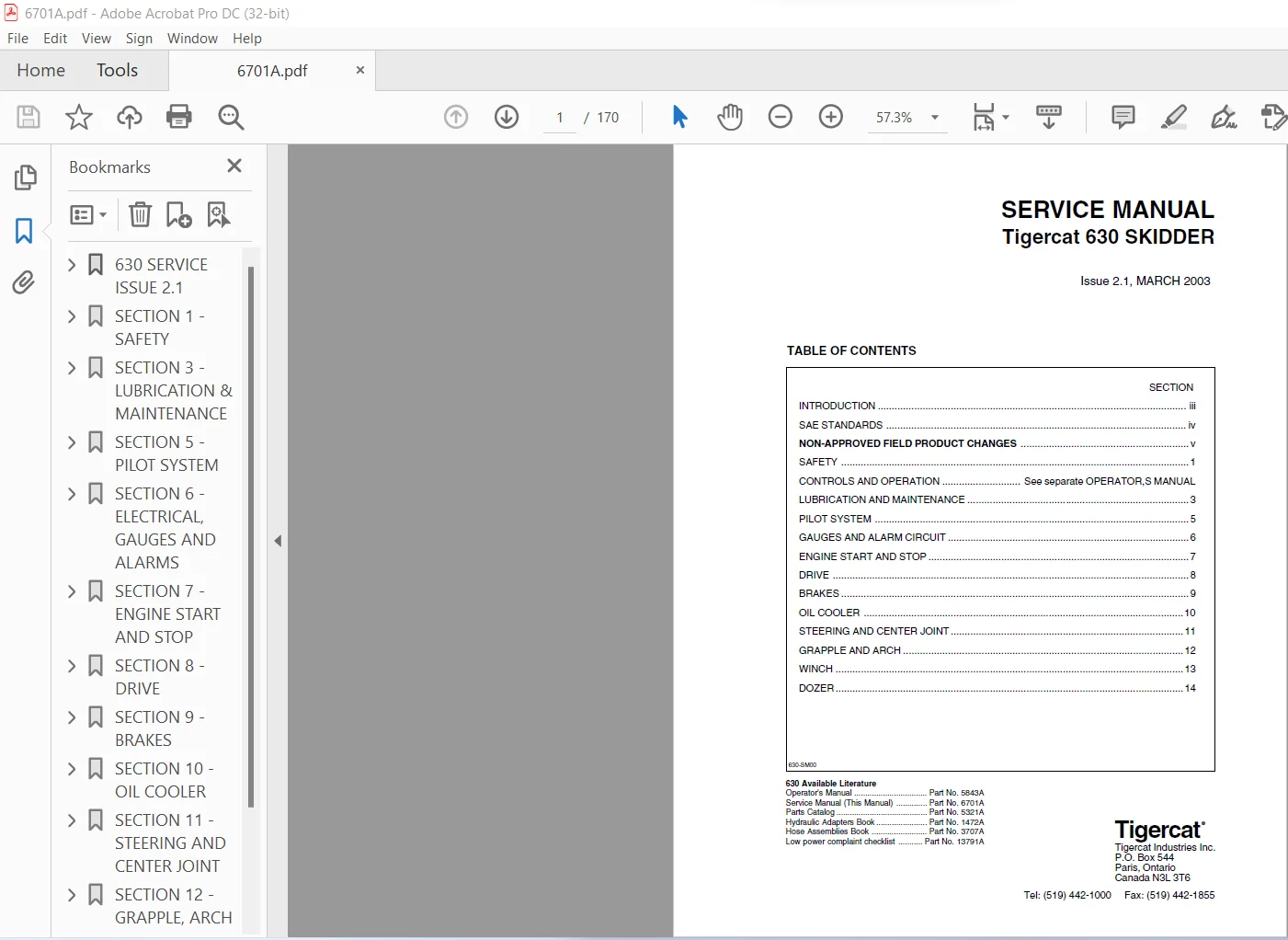
TABLE OF CONTENTS:
Tigercat 630 SKIDDER Service Manual – PDF DOWNLOAD
630 SERVICE ISSUE 21 1
INTRODUCTION 3
SAE STANDARDS 4
NON-APPROVED FIELD PRODUCT CHANGES 5
SECTION 1 – SAFETY 7
battery disconnect switch 12
cooling system 14
exhaust fumes 16
FIRE PREVENTION 7
FIRE PREVENTION GUIDELINES 17
WHAT ELSE TO DO BEFORE YOU EXPERIENCE A FIRE 18
WHAT TO DO AFTER A FIRE 19
WHAT TO DO IN CASE OF A MACHINE FIRE 18
first aid 10
Fluid leaks 14
Hydraulic Pressure hazard 14
loose clothing hazard 15
protective clothing 9
SAFETY PRECAUTIONS, GENERAL 10
SAFETY PRECAUTIONS, OPERATING 11
SAFETY PRECAUTIONS, SERVICING 14
SAFETY SYMBOLS 8
Signal Words 8
SECTION 3 – LUBRICATION & MAINTENANCE 21
center joint 37
lubrication 37
maintenance 37
FILTER AND LUBRICATION SCHEDULE 29
FILTERS – REMOVE AND REPLACE 30
FUEL FILTER/WATER SEPARATOR 30
FUEL TANK STRAINER 30
HYDRAULIC OIL RETURN FILTERS 31
HYDROSTATIC CHARGE PUMPPRESSURE FILTER 32
FUEL TANK STRAINER 30
GENERAL MAINTENANCE 23
GRAPPLE SNUBBER MAINTENANCE 36
HOUR METER ~ MAINTENANCE 22
NEW MACHINE MAINTENANCE 21
FIRST 25 HOURS 22
FIRST 250 HOURS 22
Oil lost from leakage 22
PRESSURE SETTINGS 38
SCHEDULED MAINTENANCE 24
1000 HOURS 26
125 HOURS 25
250 HOURS 25
500 HOURS 25
8 HOURS 24
FREQUENTLY 24
SEASONAL 26
SERVICING AIR CONDITIONING SYSTEM 34
STARTUP PROCEDURE AFTER MAJOR MAINTENANCE 32
TIGHTENING POINTS 22
TORQUE CHART 39
TORQUE CHART, GENERAL 40
WHEELS, INSTALLING 22
WINCH LUBRICATION 23
SECTION 5 – PILOT SYSTEM 41
CHARGE PRESSURE FILTER 42
charge pump 42
CIRCUIT DIAGRAM SERIAL NUMBER 6300101 TO 6300400 44
CIRCUIT DIAGRAM SERIAL NUMBER 6300401 TO 6300610 45
CIRCUIT DIAGRAM SERIAL NUMBER 6300611 TO 6300999 46
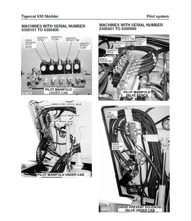
pilot manifold 43
PILOT OIL CIRCUIT 42
SET PILOT PRESSURE 42
SECTION 6 – ELECTRICAL, GAUGES AND ALARMS 47
fuse and relay panel (6300481 TO 6300999) 54
GAUGES AND ALARMS 55
SCHEMATIC DIAGRAM (6300101 to 6300400) 48
SCHEMATIC DIAGRAM (6300401 to 6300480) 50
SCHEMATIC DIAGRAM (6300481 TO 6300999) 52
SENSOR DETAILS 55
switch and sensor locations (6300101 to 6300400) 56
switch and sensor locations (6300420 to 6300500) 57
switch and sensor locations (6300501 TO 6300999) 58
troubleshooting and testing 55
wire colour code chart 54
SECTION 7 – ENGINE START AND STOP 59
CIRCUIT DESCRIPTION 60
CIRCUIT DIAGRAM 63
SERIAL NUMBERS 6300101 TO 6300400 63
SERIAL NUMBERS 6300401 TO 6300480 63
SERIAL NUMBERS 6300481 TO 6300999 64
DRIVE SYSTEM RELAYS 59
DRIVE ENABLE RELAY 60
START RELAY 60
engine Start circuit 60
fuel control valve 62
main pump unloading valve 62
parking brake switch 60
start motor and solenoid 60
start solenoid relay 61
TACHOMETER SET-UP 65
SECTION 8 – DRIVE 67
AXLES 101
capacities 103
DIFFERENTIAL AND DIFFERENTIAL LOCKS 102
DRAINING THE AXLES 103
filling the axles 103
Lubrication 103
OIL capacities 103
PLANETARY FINAL DRIVE 101
Service brakes (front axle only) 67
BRAKE BLEEDING 102
BRAKE LINING INSPECTION 102
SERVICING BRAKES 102
DRIVE SYSTEM 67
DRIVE CIRCUIT (6300101 to 6300400) 76
DRIVE CIRCUIT (6300401 to 6300999) 88
DRIVE FOOT CONTROL VALVE 73
DRIVE MOTOR DESCRIPTION 72
DRIVE MOTOR SCREW ADJUSTMENTS (6300101 to 6300400) 82
DRIVE MOTOR SCREW ADJUSTMENTS (6300401 to 6300999) 94
DRIVE PREVENT VALVE (6300101 to 6300400) 73
DRIVE PREVENT VALVE (6300401 to 6300999 74
DRIVE PUMP DESCRIPTION 70
DRIVE PUMP PRESSURE SETTINGS (6300101 to 6300400) 80
DRIVE PUMP PRESSURE SETTINGS (6300401 to 6300999) 92
DRIVE SYSTEM description 68
hydraulic set-up procedure (6300101 to 6300400) 67
Drive Motor pressure Adjustment 81
drive Pump Pressure Adjustment 79
Motor Begin of displacement control Pressure 83
Motor Minimum displacement Adjustment 82
Motor pressure override adjustment (POR) 85
hydraulic set-up procedure (6300401 to 6300999) 67
Drive Motor pressure Adjustment 94
drive Pump Pressure Adjustment 91
Motor Begin of displacement control Pressure 95
Motor Minimum displacement Adjustment 94
Motor pressure override adjustment (POR) 97
HYDRAULIC OIL HEATING PROCEDURE 75
TEST DRIVE (6300101 to 6300400) 67
Begin of Displacement Control Pressure 77
DIFFERENTIAL LOCKS 78
horsepower 78
Motor Pressure Override (POR) 77
Steering Operation 78
TEST DRIVE (6300401 to 6300999) 67
Begin of Displacement Control Pressure 89
DIFFERENTIAL LOCKS 90
horsepower 90
Motor Pressure Override (POR) 89
Steering Operation 90
TRANSMISSION 100
WHEEL INSTALLATION 103
TAPERED ASSEMBLY STUD 103
SECTION 9 – BRAKES105
ACCUMULATOR105
accumulator 106
CHARGING AND TESTING DEVICE 107
CHARGING THE ACCUMULATOR 107
CHECKING GAS PRESSURE 107
BRAKES105
ACCUMULATOR and SERVICE BRAKES 110
BRAKE PILOT VALVE 106
Parking brake 114
CHARGING VALVE, ACCUMULATOR 107
CIRCUIT DIAGRAM (6300101 TO 6300400) 111
CIRCUIT DIAGRAM (6300401 TO 6300610) 112
CIRCUIT DIAGRAM (6300611 TO 6300999) 113
DIFFERENTIAL LOCKS105
ADJUSTING DIFFERENTIAL LOCK VALVES: 109
CIRCUIT DESCRIPTION 109
Multifunction Valve105
ADJUSTING HIGH PRESS RELIEF AND MAIN PUMP 109
DESCRIPTION 108
HIGH PRESSURE RELIEF 109
Parking brake 114
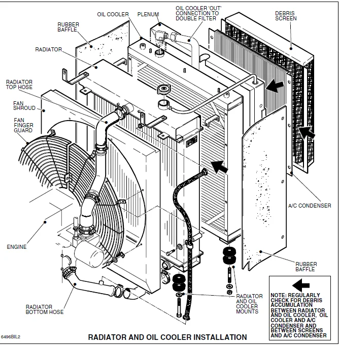
SECTION 10 – OIL COOLER115
CIRCUIT DESCRIPTION AND Operation117
serial numbers 6300101 to 6300400 117
serial numbers 6300401 TO 6300999 117
CIRCUIT DIAGRAM118
serial numbers 6300101 to 6300400 118
serial numbers 6300401 TO 6300999 119
OIL COOLER DESCRIPTION 116
SECTION 11 – STEERING AND CENTER JOINT121
center joint128
adjustment 128
checking 128
diagram 129
grease seals 129
lubrication 128
maintenance 128
CIRCUIT DIAGRAM (6300101 to 6300400) 126
CIRCUIT DIAGRAM (6300401 to 6300999) 127
PRIORITY VALVE 124
STEER CONTROL VALVE 122
testing the Steering Operation 125
SECTION 12 – GRAPPLE, ARCH AND BOOM131
CIRCUIT DESCRIPTION131
ARCH 135
ARCH/BOOM 141
grapple open/close 149
grapple rotate (6300101 to 6300400, esco grapple) 148
grapple rotate (6300401 to 6300999, tc grapple) 148
CIRCUIT DIAGRAMS131
ARCH/boom 6300101 TO 6300400 142
ARCH/boom 6300401 TO 6300999 143
GRAPPLE 6300101 TO 6300400 150
GRAPPLE 6300401 TO 6300999 151
SINGLE ARCH 6300101 TO 6300400 136
SINGLE ARCH 6300401 TO 6300999 137
GRAPPLE CONTROL VALVE131
dual FUNCTION ARCH SECTION 140
grapple rotate and open/close SECTIONs 146
SINGLE FUNCTION ARCH SECTION 134
grapple snubber maintenance 153
JOYSTICK CONTROL VALVE, arch and grapple 133
PORT RELIEF VALVE DESCRIPTION (GRAPPLE VALVE) 154
ADJUSTING PROCEDURE 153
PRESSURE SETTINGS131
DUAL ARCH/BOOM 145
GRAPPLE rotate 152
GRAPPLE OPEN/CLOSE 152
SINGLE ARCH 135
SECTION 13 – WINCH155
CIRCUIT DESCRIPTION 158
winch 159
CIRCUIT DIAGRAMS155
WINCH 6300101 TO 6300400 160
WINCH 6300401 TO 6300999 161
CONTROL LEVER valve 156
GRAPPLE CONTROL VALVE155
WINCH SECTION 157
PRESSURE SETTINGS155
winch NONE ADJUSTABLE 159
SECTION 14 – DOZER BLADE163
CIRCUIT DESCRIPTION 166
circuit diagrams163
DOZER 6300101 TO 6300400 168
DOZER 6300401 TO 6300999 169
CONTROL LEVER PILOT VALVE 164
dozer CONTROL VALVE 164
pressure settings 166
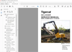
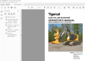
IMAGES PREVIEW OF THE MANUAL:
TIGERCAT 630 SKIDDER SERVICE MANUAL – PDF DOWNLOAD:
PLEASE NOTE:
- This is the same manual used by the dealers to diagnose and troubleshoot your vehicle
- You will be directed to the download page as soon as the purchase is completed. The whole payment and downloading process will take anywhere between 2-5 minutes
- Need any other service / repair / parts manual, please feel free to contact [email protected] . We still have 50,000 manuals unlisted
S.V
![Tigercat ВАЛОЧНО-ПАКЕТИРУЮЩАЯ МАШИНА 860C 870C L870C РУКОВОДСТВО ПО ОБСЛУЖИВАНИЮ - [Russian]](https://heydownloads.com/wp-content/uploads/2022/01/Tigercat-ВАЛОЧНО-ПАКЕТИРУЮЩАЯ-МАШИНА-860C-870C-L870C-РУКОВОДСТВО-ПО-ОБСЛУЖИВАНИЮ-1-300x215.webp)