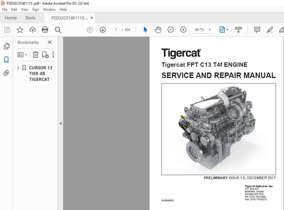
Tigercat FPT C13 T4f ENGINE SERVICE & REPAIR MANUAL – PDF DOWNLOAD
Original price was: $79.95.$29.95Current price is: $29.95.
Tigercat FPT C13 T4f ENGINE SERVICE & REPAIR MANUAL – PDF DOWNLOAD
Description
Tigercat FPT C13 T4f ENGINE SERVICE & REPAIR MANUAL – PDF DOWNLOAD
TABLE OF CONTENTS:
Tigercat FPT C13 T4f ENGINE SERVICE & REPAIR MANUAL – PDF DOWNLOAD
CURSOR 13 TIER 4B TIGERCAT…………………………………………………………………………………………………. 0
Contents……………………………………………………………………………………………………………… 3
Technical repair manual…………………………………………………………………………………………….. 5
INTRODUCTION…………………………………………………………………………………………………… 7
SYMBOLS – WARNINGS………………………………………………………………………………………….. 9
SYMBOLS – SERVICE OPERATIONS…………………………………………………………………………………. 10
GENERAL WARNINGS……………………………………………………………………………………………. 11
GENERAL WARNINGS REGARDING THE ELECTRICAL SYSTEM……………………………………………………………….. 12
Grounding and screening……………………………………………………………………………………… 13
Optional electrical and mechanical parts installations………………………………………………………….. 14
Conversions between the main units of measurement of the international system and the most commonly used derived sizes…. 15
Power………………………………………………………………………………………………….. 15
Torque…………………………………………………………………………………………………. 15
Revolutions per time unit………………………………………………………………………………… 15
Pressure……………………………………………………………………………………………….. 15
Temperature…………………………………………………………………………………………….. 15
Update data………………………………………………………………………………………………… 16
General information………………………………………………………………………………………………… 17
General information ……………………………………………………………………………………………. 19
CORRESPONDENCE BETWEEN TECHNICAL CODES AND COMMERCIAL CODES……………………………………………………… 21
TECHNICAL CODES…………………………………………………………………………………………….. 21
COMMERCIAL CODES……………………………………………………………………………………………. 21
ISOMETRIC VIEW……………………………………………………………………………………………… 22
CHARACTERISTIC CURVES……………………………………………………………………………………….. 24
Maximum power 407 kW…………………………………………………………………………………….. 24
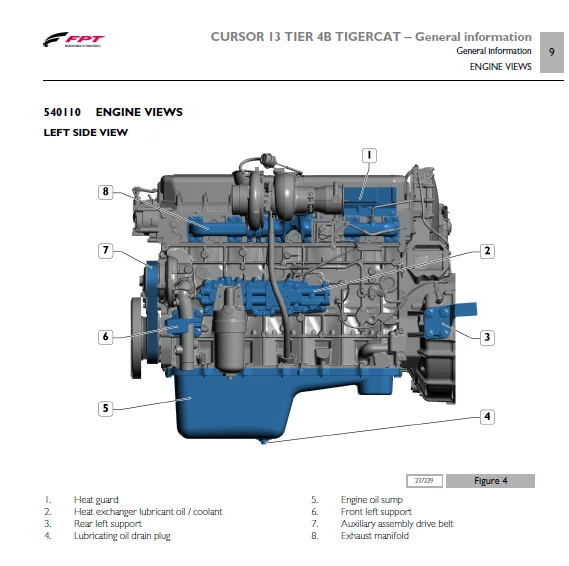
ENGINE VIEWS……………………………………………………………………………………………….. 25
GENERAL CHARACTERISTICS……………………………………………………………………………………… 29
Operating diagrams…………………………………………………………………………………………………. 33
Operating diagrams …………………………………………………………………………………………….. 35
SUPPLY SYSTEM………………………………………………………………………………………………. 37
SUPPLY SYSTEM COMPONENTS…………………………………………………………………………………….. 38
High pressure pump CPN 5-22/2…………………………………………………………………………….. 38
High pressure pump section……………………………………………………………………………. 40
Pressure accumulator (Common rail) HFRN-22…………………………………………………………………. 40
Electro-injector CRIN 3-22……………………………………………………………………………….. 42
operation…………………………………………………………………………………………… 43
Pressure limiter valve…………………………………………………………………………………… 44
Fuel filter…………………………………………………………………………………………….. 44
LUBRICATION CIRCUIT…………………………………………………………………………………………. 45
Lubrication circuit……………………………………………………………………………………… 45
LUBRICATION CIRCUIT COMPONENTS……………………………………………………………………………….. 46
Oil pump……………………………………………………………………………………………….. 46
Oil pump cross-section……………………………………………………………………………….. 46
Overpressure valve………………………………………………………………………………………. 47
Main data to check the overpressure valve spring………………………………………………………… 47
Oil pressure regulator valve……………………………………………………………………………… 47
Heat exchanger………………………………………………………………………………………….. 49
Filter by-pass valve…………………………………………………………………………………….. 50
Engine oil filter……………………………………………………………………………………….. 51
Valve integrated in piston cooling nozzle………………………………………………………………….. 52
OIL VAPOUR RECIRCULATION SYSTEM (BLOW BY SYSTEM)……………………………………………………………….. 52
COOLING CIRCUIT…………………………………………………………………………………………….. 54
Description…………………………………………………………………………………………….. 54
operation………………………………………………………………………………………………. 55
COOLING CIRCUIT COMPONENTS…………………………………………………………………………………… 55
Water pump……………………………………………………………………………………………… 55
Section on water pump………………………………………………………………………………… 55
Thermostat……………………………………………………………………………………………… 55
Water circulating in the engine……………………………………………………………………….. 55
Water leaving the thermostat………………………………………………………………………….. 56
INTAKE AND EXHAUST SYSTEM……………………………………………………………………………………. 56
Turbocharging diagram……………………………………………………………………………………. 57
INTAKE AND EXHAUST SYSTEM COMPONENTS………………………………………………………………………….. 58
HTT Wastegate turbocharger……………………………………………………………………………….. 58
Turbocharger actuator……………………………………………………………………………………. 59
Motorised throttle valve on the exhaust (Exhaust Flap)………………………………………………………. 60
EXHAUST GAS POST-TREATMENT SYSTEM(ATS)………………………………………………………………………… 61
General information……………………………………………………………………………………… 61
………………………………………………………………………………………………….. 64
AdBlue specifications………………………………………………………………………………… 67
ATS components………………………………………………………………………………………….. 68
Tank……………………………………………………………………………………………….. 68
AdBlue fluid level gauge control………………………………………………………………………. 69
DeNOx 2.2 (SM) supply module………………………………………………………………………….. 71
Dosing module 2.5DeNOx 2.2 (DM)……………………………………………………………………….. 72
Engine coolant 3-way valve……………………………………………………………………………. 72
Electric/electronic system………………………………………………………………………………………….. 73
ELECTRIC EQUIPMENT……………………………………………………………………………………………… 75
Location of engine electrical components………………………………………………………………………. 77
ENGINE SIDE WIRING………………………………………………………………………………………….. 79
Cable on engine…………………………………………………………………………………………. 79
Wiring-topographic diagram – Engine side…………………………………………………………………… 82
Head wiring…………………………………………………………………………………………….. 83
ECU……………………………………………………………………………………………………….. 85
EDC17CV41 control unit…………………………………………………………………………………… 85
EDC (ECM) SYSTEM………………………………………………………………………………………… 86
EDC SYSTEM OPERATION…………………………………………………………………………………….. 86
Fuel dosing…………………………………………………………………………………………. 86
Correcting flow rate according to water temperature……………………………………………………… 87
De-rating…………………………………………………………………………………………… 87
Injection advance electronic control…………………………………………………………………… 87
Engine speed limiter…………………………………………………………………………………. 87
Starting the engine………………………………………………………………………………….. 87
Run Up……………………………………………………………………………………………… 88
After run…………………………………………………………………………………………… 88
Cut – off…………………………………………………………………………………………… 88
Cylinder Balancing…………………………………………………………………………………… 88
Synchronisation Search……………………………………………………………………………….. 88
EDC17CV41 control unit……………………………………………………………………………….. 89
ELECTRONIC COMPONENTS……………………………………………………………………………………….. 93
Electro-injectors……………………………………………………………………………………….. 93
Rail pressure sensor (RPS)……………………………………………………………………………….. 94
technical specifications……………………………………………………………………………… 94
Fuel metering valve……………………………………………………………………………………… 96
Fuel temperature sensor………………………………………………………………………………….. 97
technical specifications……………………………………………………………………………… 98
Engine coolant temperature sensor…………………………………………………………………………. 98
technical specifications………………………………………………………………………………100
Crankshaft rpm sensor…………………………………………………………………………………….100
Sensor………………………………………………………………………………………………101
Characteristics:……………………………………………………………………………………..101
Camshaft timing sensor……………………………………………………………………………………102
Sensor………………………………………………………………………………………………102
Characteristics………………………………………………………………………………………103
Air temperature and boost pressure sensor…………………………………………………………………..103
technical specifications………………………………………………………………………………105
Crankcase pressure sensor…………………………………………………………………………………106
technical specifications………………………………………………………………………………107
Engine oil temperature and pressure sensor………………………………………………………………….107
technical specifications………………………………………………………………………………109
Motorised throttle valve actuator (Exhaust Flap)…………………………………………………………….111
Engine pre/post heating resistor…………………………………………………………………………..111
technical specifications………………………………………………………………………………112
Alternator………………………………………………………………………………………………113
Characteristics………………………………………………………………………………………113
Alternator current delivery curve………………………………………………………………………114
Perspective view……………………………………………………………………………………..114
Technical view……………………………………………………………………………………….115
Starter motor……………………………………………………………………………………………115
Characteristics………………………………………………………………………………………115
Technical view……………………………………………………………………………………….116
Characteristic curves…………………………………………………………………………………116
Wiring Diagram……………………………………………………………………………………….117
ATS SYSTEM ELECTRICAL COMPONENTS………………………………………………………………………………118
Exhaust gas temperature sensor…………………………………………………………………………….118
Nitrogen oxide detecting sensor (NOx)………………………………………………………………………119
NOx control unit……………………………………………………………………………………..120
technical specifications………………………………………………………………………………120
Nitrogen oxide NOx sensor……………………………………………………………………………..121
technical specifications………………………………………………………………………………122
NH 3 control unit………………………………………………………………………………………..122
technical specifications………………………………………………………………………………123
Ammonia detection sensor NH3………………………………………………………………………………124
Technical specifications………………………………………………………………………………125
Air humidity/temperature sensor……………………………………………………………………………125
Denox 2.2 supply module (SM)………………………………………………………………………………127
Pin out connector………………………………………………………………………………………..128
Electrical components inside the supply module………………………………………………………………129
Component characteristics……………………………………………………………………………..129
Dosing module DeNOx 2.5 (DM)………………………………………………………………………………131
Engine coolant 3-way valve………………………………………………………………………………..132
Scheduled maintenance……………………………………………………………………………………………….135
SCHEDULED MAINTENANCE……………………………………………………………………………………………137
Introduction………………………………………………………………………………………………..139
Checks and scheduled maintenance procedures…………………………………………………………………….139
CHECKS TO PERFORM DURING PERIOD OF USE…………………………………………………………………………140
Check engine oil level……………………………………………………………………………………140
Coolant level check………………………………………………………………………………………141
Engine visual inspection………………………………………………………………………………….141
Draining the water from the fuel pre-filter…………………………………………………………………142
Check tension and condition of ancillary belt……………………………………………………………….142
Check the condition of the exhaust duct(s)………………………………………………………………….143
PERIODICAL MAINTENANCE……………………………………………………………………………………….143
Change engine lubricant oil……………………………………………………………………………….143
Replacing the engine oil filter……………………………………………………………………………144
Fuel pre-filter replacement……………………………………………………………………………….145
Replacing fuel filter…………………………………………………………………………………….145
Replacing the auxiliary assembly drive belt…………………………………………………………………146
Change blow-by filter…………………………………………………………………………………….147
UNSCHEDULED MAINTENANCE………………………………………………………………………………………148
Replacing automatic belt tensioner and guide pulley assembly………………………………………………….148
Intake and exhaust rocker arm clearance adjustment…………………………………………………………..152
Replace engine coolant……………………………………………………………………………………155
SCHEDULED MAINTENANCE FOR ATS SYSTEM…………………………………………………………………………..156
ATS system maintenance services schedule……………………………………………………………………156
Location of the ATS system filters…………………………………………………………………………157
Replacing the AdBlue filter……………………………………………………………………………….157
Removal……………………………………………………………………………………………..157
Assembly…………………………………………………………………………………………….159
Removal-refitting of the main engine components………………………………………………………………………..161
Removal – refitting of main components…………………………………………………………………………….163
Removal-refitting of ancillary belt……………………………………………………………………………165
Alternator removal-refitting………………………………………………………………………………….166
Removal – refitting of the automatic belt tensioner……………………………………………………………..167
Removal – Refitting of the fan pulley………………………………………………………………………….168
Water pump removal-refitting………………………………………………………………………………….170
Removal – refitting of the thermostat………………………………………………………………………….171
Starter motor removal-refitting……………………………………………………………………………….173
Engine cable removal-refitting………………………………………………………………………………..174
Removal – Refitting of motorised throttle valve (Exhaust flap)……………………………………………………175
Turbocharger removal-refitting………………………………………………………………………………..177
Exhaust manifold removal-refitting…………………………………………………………………………….180
Engine oil filter removal – refitting………………………………………………………………………….183
Heat exchanger removal-refitting………………………………………………………………………………184
Oil sump removal-refitting……………………………………………………………………………………186
Removal -Refitting of suction strainer and recover oil in sump……………………………………………………188
Fuel filter removal-refitting…………………………………………………………………………………190
Removal – refitting of the fuel pipes………………………………………………………………………….191
Removal – Refitting vehicle fuel filter mount…………………………………………………………………..194
Removal – Refitting of oil filler pipe and dipstick……………………………………………………………..195
Removal – Refitting of the EDC 17CV41 control unit………………………………………………………………196
Blow-by filter removal – refitting…………………………………………………………………………….198
Removal – refitting of the high pressure pump…………………………………………………………………..199
Intake manifold removal-refitting……………………………………………………………………………..202
Tappet cover removal-refitting………………………………………………………………………………..204
Removal – refitting of the rocker arm unit……………………………………………………………………..206
Removal – refitting the electro-injector wirings………………………………………………………………..212
Common rail removal-refitting…………………………………………………………………………………213
Removal – refitting of the electro-injectors……………………………………………………………………217
Cylinder head removal-refitting……………………………………………………………………………….221
Removal – refitting of the damper flywheel……………………………………………………………………..224
Removal – refitting of the crankshaft drive pulley………………………………………………………………226
Removal – Refitting of the crankshaft front sealing ring…………………………………………………………227
Removal – refitting of the engine flywheel……………………………………………………………………..229
Removal – refitting of the crankshaft rear seal ring…………………………………………………………….230
General mechanical overhaul………………………………………………………………………………………….233
GENERAL MECHANICAL OVERHAUL………………………………………………………………………………………235
ENGINE DISASSEMBLING AT BENCH…………………………………………………………………………………237
COMPREHENSIVE CRANKCASE CHECKS………………………………………………………………………………..272
OVERHAULING THE CONNECTING ROD-PISTON ASSEMBLY………………………………………………………………….298
CYLINDER HEAD OVERHAUL……………………………………………………………………………………….307
COMPLETE TIMING SYSTEM OVERHAUL……………………………………………………………………………….315
ENGINE ASSEMBLY……………………………………………………………………………………………..324
Technical specifications…………………………………………………………………………………………….385
Technical specifications ………………………………………………………………………………………..387
DATA – INSTALLATION CLEARANCES………………………………………………………………………………..389
Cylinder assembly and crank gears………………………………………………………………………….389
Cylinder head – Timing system……………………………………………………………………………..392
TIGHTENING TORQUES…………………………………………………………………………………………..394
TIGHTENING TORQUES ………………………………………………………………………………………394
Equipment………………………………………………………………………………………………………….403
TOOLS………………………………………………………………………………………………………….405
FPT DIAGNOSTICS EQUIPMENT…………………………………………………………………………………….407
TOOLS ……………………………………………………………………………………………………..408
Safety regulations………………………………………………………………………………………………….419
SAFETY REGULATIONS………………………………………………………………………………………………421
Standard safety precautions…………………………………………………………………………………..423
Accident prevention………………………………………………………………………………………….423
During maintenance…………………………………………………………………………………………..423
Protection of the environment…………………………………………………………………………………424
DESCRIPTION:
Tigercat FPT C13 T4f ENGINE SERVICE & REPAIR MANUAL – PDF DOWNLOAD
INTRODUCTION :
This document provides data, specifications, instructions and methods to perform repair interventions on the assembly and its components. Anyhow, this document is addressed to qualified and specialised personnel. Before performing any intervention, check that the document relating to the vehicle model on which the intervention is being performed is available and also make sure that all accident prevention devices, including but not limited to, goggles, helmet, gloves, shoes, as well as work equipment, lifting and transport equipment, etc., are available and efficient, and also make sure that the unit is in safety conditions for intervention.
- Carrying out interventions which fully comply with the indications given here, as well as the use of the specific equipment indicated, ensures repair interventions are carried out correctly, timings are respected and the operator’s safety is safeguarded. Each repair intervention must be finalised to the recovery of functionality, efficiency and safety conditions that are provided by FPT.
- Each intervention on the unit aimed at a modification, alteration or other which has not been authorised by FPT relieves FPT of any liability, and, in particular, where the assembly is covered by a warranty, each intervention will immediately invalidate the warranty. FPT declines any liability for repair work.
- FPT is available to provide any information necessary for the execution of the interventions and to provide instructions for any cases and situations not covered in this publication. The data contained in this issue may not be up-to-date due to possible modifications made by the Manufacturer for technical or commercial reasons, or to adaptations required by laws in force in different countries. In the event of discordance between the information in this publication and the actual assembly, please contact the FPT network before performing any interventions.
- The complete or partial reproduction of the text or illustrations herein is forbidden. Manuals for repairs are split into Sections, each one of which is marked by a numeral; the contents of these sections are indicated in the general table of contents.
- Sections with mechanical contents include technical data, tightening torque tables, tool lists, assembly/component connections – disconnections, overhauls at the bench and scheduled maintenance. In the electrical/electronic system section there are the descriptions of the electric network and the electronic systems of the assembly, wiring diagrams, electrical characteristics of components and the component codes
IMAGES PREVIEW OF THE MANUAL:
TIGERCAT FPT C13 T4F ENGINE SERVICE & REPAIR MANUAL – PDF DOWNLOAD:
PLEASE NOTE:
- This is the SAME MANUAL used by the dealerships to diagnose your vehicle
- No waiting for couriers / posts as this is a PDF manual and you can download it within 2 minutes time once you make the payment.
- Your payment is all safe and the delivery of the manual is INSTANT – You will be taken to the DOWNLOAD PAGE.
- So have no hesitations whatsoever and write to us about any queries you may have : heydownloadss @gmail.com
S.V

![Tigercat 860C 870C L870C ВАЛОЧНО-ПАКЕТИРУЮЩАЯ МАШИНА РУКОВОДСТВО ПО ОБСЛУЖИВАНИЮ - [Russian]](https://heydownloads.com/wp-content/uploads/2022/01/Tigercat-860C-870C-L870C-ВАЛОЧНО-ПАКЕТИРУЮЩАЯ-МАШИНА-РУКОВОДСТВО-ПО-ОБСЛУЖИВАНИЮ-3-300x219.webp)