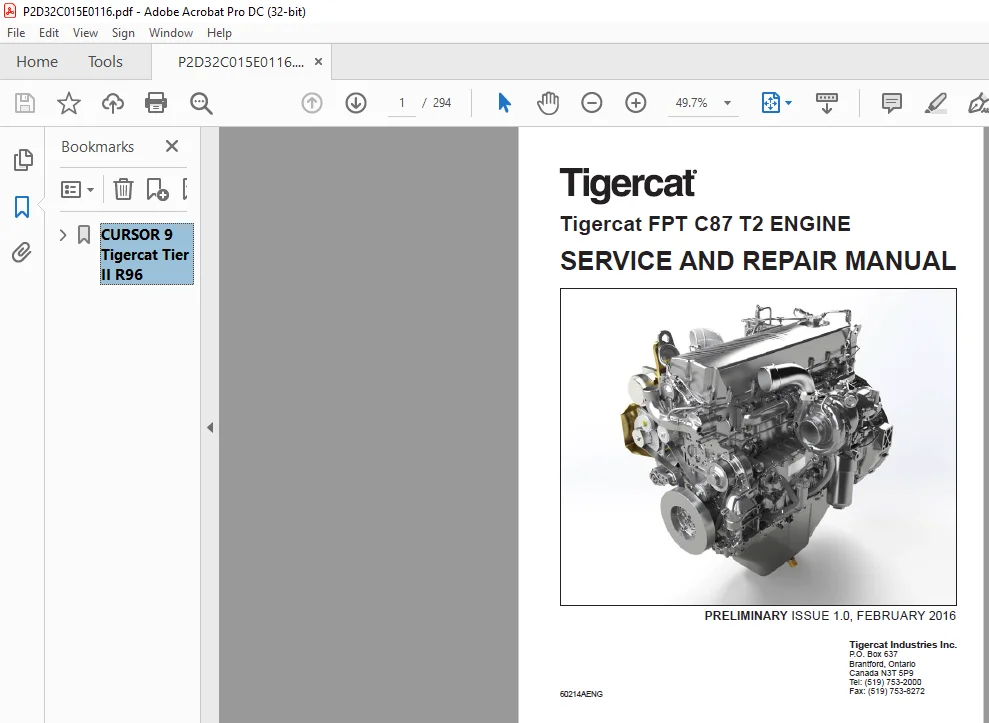
Tigercat FPT C87 T2 ENGINE Service & Repair Manual – PDF DOWNLOAD
Original price was: $89.95.$28.95Current price is: $28.95.
Tigercat FPT C87 T2 ENGINE Service & Repair Manual – PDF DOWNLOAD
Description
Tigercat FPT C87 T2 ENGINE Service & Repair Manual – PDF DOWNLOAD
TABLE OF CONTENTS:
Tigercat FPT C87 T2 ENGINE Service & Repair Manual – PDF DOWNLOAD
CURSOR 9 Tigercat Tier II R96………………………………………………………………………………………………. 0
Contents……………………………………………………………………………………………………………… 3
Technical repair manual…………………………………………………………………………………………….. 5
INTRODUCTION…………………………………………………………………………………………………… 7
SYMBOLS – WARNINGS………………………………………………………………………………………….. 9
SYMBOLS – SERVICE OPERATIONS…………………………………………………………………………………. 10
GENERAL WARNINGS……………………………………………………………………………………………. 11
GENERAL WARNINGS REGARDING THE ELECTRICAL SYSTEM……………………………………………………………….. 12
Grounding and screening……………………………………………………………………………………… 13
Optional electrical and mechanical parts installations………………………………………………………….. 14
Conversions between the main units of measurement of the international system and the most commonly used derived sizes…. 15
Power………………………………………………………………………………………………….. 15
Torque…………………………………………………………………………………………………. 15
Revolutions per time unit………………………………………………………………………………… 15
Pressure……………………………………………………………………………………………….. 15
Temperature…………………………………………………………………………………………….. 15
update data………………………………………………………………………………………………… 16
General information………………………………………………………………………………………………… 17
General information ……………………………………………………………………………………………. 19
IDENTIFICATION PLATE………………………………………………………………………………………… 21
Identification plate…………………………………………………………………………………….. 21
CORRESPONDENCE BETWEEN TECHNICAL CODES AND COMMERCIAL CODES……………………………………………………… 21
CORRESPONDENCE BETWEEN TECHNICAL CODES AND COMMERCIAL CODES …………………………………………………. 21
TECHNICAL CODES…………………………………………………………………………………………….. 21
TECHNICAL CODES ………………………………………………………………………………………… 21
COMMERCIAL CODES……………………………………………………………………………………………. 22
COMMERCIAL CODES ……………………………………………………………………………………….. 22
ISOMETRIC VIEW……………………………………………………………………………………………… 23
ISO VIEW……………………………………………………………………………………………….. 23
CHARACTERISTIC CURVES……………………………………………………………………………………….. 25
CHARACTERISTIC CURVES F2CFA613T…………………………………………………………………………… 25
ENGINE VIEWS……………………………………………………………………………………………….. 26
ENGINE VIEWS …………………………………………………………………………………………… 26
FRONT VIEW………………………………………………………………………………………….. 26
REAR VIEW…………………………………………………………………………………………… 27
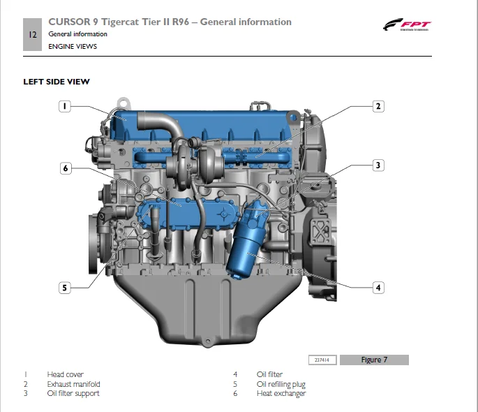
LEFT SIDE VIEW………………………………………………………………………………………. 28
RIGHT SIDE VIEW……………………………………………………………………………………… 29
GENERAL CHARACTERISTICS……………………………………………………………………………………… 29
Operating diagrams…………………………………………………………………………………………………. 33
OPERATING DIAGRAMS……………………………………………………………………………………………… 35
FUEL SUPPLY………………………………………………………………………………………………… 37
Supply…………………………………………………………………………………………………. 37
ENGINE FUEL SUPPLY DIAGRAM……………………………………………………………………………. 38
FUEL SUPPLY COMPONENTS…………………………………………………………………………………… 39
Mechanical supply pump……………………………………………………………………………….. 39
High pressure pump CP 3.3…………………………………………………………………………….. 40
Rail (pressure accumulator)…………………………………………………………………………… 46
Fuel filter…………………………………………………………………………………………. 47
LUBRICATION………………………………………………………………………………………………… 48
lubrication…………………………………………………………………………………………….. 48
Lubrication circuit………………………………………………………………………………….. 48
LUBRICATION CIRCUIT COMPONENTS……………………………………………………………………………. 49
Oil pump……………………………………………………………………………………………. 49
Overpressure valve…………………………………………………………………………………… 50
Oil pressure regulator valve………………………………………………………………………….. 50
Engine oil filter……………………………………………………………………………………. 52
Filter by-pass valve…………………………………………………………………………………. 53
Disassembly…………………………………………………………………………………………. 53
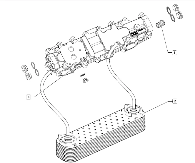
Heat exchanger………………………………………………………………………………………. 55
OIL VAPOURS………………………………………………………………………………………………… 56
Oil vapour recirculation (Blow-by)………………………………………………………………………… 56
COOLANT CIRCUIT…………………………………………………………………………………………….. 57
Cooling………………………………………………………………………………………………… 57
Description…………………………………………………………………………………………. 57
operation…………………………………………………………………………………………… 57
Coolant diagram……………………………………………………………………………………… 58
COOLING CIRCUIT COMPONENTS……………………………………………………………………………….. 59
Water pump………………………………………………………………………………………….. 59
TURBOCHARGING………………………………………………………………………………………………. 59
Turbocharging…………………………………………………………………………………………… 59
Turbocharging diagram………………………………………………………………………………… 60
Honeywell waste-gate turbocharger…………………………………………………………………………. 61
Electric/electronic system………………………………………………………………………………………….. 63
ELECTRIC/ELECTRONIC SYSTEM………………………………………………………………………………………. 65
ENGINE CABLE……………………………………………………………………………………………….. 67
……………………………………………………………………………………………………… 67
WIRE DIAGRAM……………………………………………………………………………………………….. 70
ECU……………………………………………………………………………………………………….. 71
EDC17CV41 electronic control unit…………………………………………………………………………. 71
EDC system operation…………………………………………………………………………………….. 72
Engine side pin out……………………………………………………………………………………… 76
EDC (ECM) SYSTEM……………………………………………………………………………………………. 78
Electro-injectors……………………………………………………………………………………….. 79
Fuel metering valve……………………………………………………………………………………… 80
Rail pressure sensor (RPS)……………………………………………………………………………….. 81
Technical specifications……………………………………………………………………………… 82
CPS pressure sensor……………………………………………………………………………………… 83
Technical specifications……………………………………………………………………………… 83
Flywheel pulse transmitter……………………………………………………………………………….. 83
Sensor……………………………………………………………………………………………… 84
Characteristics:…………………………………………………………………………………….. 84
Timing system pulse transmitter…………………………………………………………………………… 85
Sensor……………………………………………………………………………………………… 86
Characteristics……………………………………………………………………………………… 86
Fuel temperature sensor………………………………………………………………………………….. 87
Technical specifications……………………………………………………………………………… 89
Fuel filter clogged sensor……………………………………………………………………………….. 90
Engine coolant temperature / engine fan sensor……………………………………………………………… 91
Technical specifications……………………………………………………………………………… 92
Oil pressure and temperature sensor……………………………………………………………………….. 92
Technical specifications……………………………………………………………………………… 94
Air temperature and pressure sensor……………………………………………………………………….. 95
Technical specifications……………………………………………………………………………… 97
Pre/post heating element…………………………………………………………………………………. 98
Technical specifications……………………………………………………………………………… 99
STARTER MOTOR NIPPONDENSO 24V – 5.5KW STARTER MOTOR – [08000]…………………………………………………100
Technical view……………………………………………………………………………………….100
Characteristic curves…………………………………………………………………………………100
Wiring Diagram……………………………………………………………………………………….101
Perspective view with matching electrical connections…………………………………………………….102
Scheduled maintenance……………………………………………………………………………………………….105
SCHEDULED MAINTENANCE……………………………………………………………………………………………107
Introduction………………………………………………………………………………………………..109
Checks not included in the daily checks-maintenance schedule………………………………………………….110
MAINTENANCE PROCEDURES……………………………………………………………………………………….110
Checks………………………………………………………………………………………………….110
Check lubrication system………………………………………………………………………………110
Fuel system inspection………………………………………………………………………………..111
Checking belt tension…………………………………………………………………………………111
Checking for any tears and the state of wear of the belt………………………………………………….111
Cooling system inspection……………………………………………………………………………..111
Check engine lubricant oil level…………………………………………………………………………..112
Checking the engine coolant level………………………………………………………………………….113
SCHEDULED MAINTENANCE ……………………………………………………………………………………….113
Ancillary belt replacement………………………………………………………………………………..113
Change engine lubricant oil……………………………………………………………………………….114
Replacing the oil filter………………………………………………………………………………….115
Change blow-by filter…………………………………………………………………………………….116
Replacing fuel filter…………………………………………………………………………………….116
Fuel bleeding………………………………………………………………………………………..117
Replacing the fuel prefilter………………………………………………………………………………117
SPECIAL MAINTENANCE………………………………………………………………………………………….118
Replacement of the coolant………………………………………………………………………………..118
Adjustment of valve/rocker arm clearance……………………………………………………………………118
FIRING ORDER 1-4-2-6-3-5………………………………………………………………………………119
Removal-refitting of the main engine components………………………………………………………………………..121
Removal – refitting of main components…………………………………………………………………………….123
Removal-refitting of ancillary belt……………………………………………………………………………125
Alternator removal-refitting………………………………………………………………………………….126
Removal – Refitting the thermostat cover……………………………………………………………………….126
Water pump removal-refitting………………………………………………………………………………….128
Engine cable removal-refitting………………………………………………………………………………..129
Removal – refitting of the EDC 17 control unit………………………………………………………………….130
Fuel filter removal-refitting…………………………………………………………………………………131
Removal – Refitting vehicle fuel filter mount…………………………………………………………………..132
Turbocharger removal-refitting………………………………………………………………………………..134
Exhaust manifold removal-refitting…………………………………………………………………………….136
Intake manifold removal-refitting……………………………………………………………………………..137
Engine oil filter removal – refitting………………………………………………………………………….138
Heat exchanger removal-refitting………………………………………………………………………………139
Starter motor removal-refitting……………………………………………………………………………….142
Removal – refitting of the fuel pipes………………………………………………………………………….142
Removal – refitting of the high pressure pump…………………………………………………………………..145
Removal – Refitting of air compressor seat cover………………………………………………………………..146
Oil sump removal-refitting……………………………………………………………………………………146
Tappet cover removal-refitting………………………………………………………………………………..148
Removal – refitting of the rocker arm unit……………………………………………………………………..149
Common rail removal-refitting…………………………………………………………………………………151
Removal – refitting of the electro-injectors……………………………………………………………………153
Cylinder head removal-refitting……………………………………………………………………………….155
Removal – refitting of the damper flywheel……………………………………………………………………..157
Change blow-by filter………………………………………………………………………………………..158
General mechanical overhaul………………………………………………………………………………………….161
General mechanical overhaul ……………………………………………………………………………………..163
ENGINE DISASSEMBLING…………………………………………………………………………………………165
CYLINDER UNIT REPAIR OPERATIONS……………………………………………………………………………….184
OVERHAULING THE CONNECTING ROD-PISTON ASSEMBLY………………………………………………………………….203
CYLINDER HEAD OVERHAUL……………………………………………………………………………………….215
COMPLETE TIMING SYSTEM OVERHAUL……………………………………………………………………………….217
ENGINE ASSEMBLY……………………………………………………………………………………………..223
Technical specifications…………………………………………………………………………………………….261
Technical specifications ………………………………………………………………………………………..263
DATA – INSTALLATION CLEARANCES………………………………………………………………………………..265
Data – installation clearances…………………………………………………………………………….265
TIGHTENING TORQUES…………………………………………………………………………………………..270
Tightening torques……………………………………………………………………………………….270
Torques……………………………………………………………………………………………..270
Equipment………………………………………………………………………………………………………….275
TOOLS………………………………………………………………………………………………………….277
………………………………………………………………………………………………………….279
Safety regulations………………………………………………………………………………………………….289
SAFETY REGULATIONS………………………………………………………………………………………………291
Standard safety precautions…………………………………………………………………………………..293
Accident prevention………………………………………………………………………………………….293
During maintenance…………………………………………………………………………………………..293
Protection of the environment…………………………………………………………………………………294
DESCRIPTION:
Tigercat FPT C87 T2 ENGINE Service & Repair Manual – PDF DOWNLOAD
INTRODUCTION :
This document provides data, specifications, instructions and methods to perform repair interventions on the assembly and its components. Anyhow, this document is addressed to qualified and specialised personnel. Before performing any intervention, check that the document relating to the vehicle model on which the intervention is being performed is available and also make sure that all accident prevention devices, including but not limited to, goggles, helmet, gloves, shoes, as well as work equipment, lifting and transport equipment, etc., are available and efficient, and also make sure that the unit is in safety conditions for intervention.
- Carrying out interventions which fully comply with the indications given here, as well as the use of the specific equipment indicated, ensures repair interventions are carried out correctly, timings are respected and the operator’s safety is safeguarded. Each repair intervention must be finalised to the recovery of functionality, efficiency and safety conditions that are provided by FPT.
- Each intervention on the unit aimed at a modification, alteration or other which has not been authorised by FPT relieves FPT of any liability, and, in particular, where the assembly is covered by a warranty, each intervention will immediately invalidate the warranty. FPT declines any liability for repair work. FPT is available to provide any information necessary for the execution of the interventions and to provide instructions for any cases and situations not covered in this publication.
- The data contained in this issue may not be up-to-date due to possible modifications made by the Manufacturer for technical or commercial reasons, or to adaptations required by laws in force in different countries. In the event of discordance between the information in this publication and the actual assembly, please contact the FPT network before performing any interventions.
- The complete or partial reproduction of the text or illustrations herein is forbidden. Manuals for repairs are split into Sections, each one of which is marked by a numeral; the contents of these sections are indicated in the general table of contents. Sections with mechanical contents include technical data, tightening torque tables, tool lists, assembly/component connections – disconnections, overhauls at the bench and scheduled maintenance.
IMAGES PREVIEW OF THE MANUAL:
TIGERCAT FPT C87 T2 ENGINE SERVICE & REPAIR MANUAL – PDF DOWNLOAD:
PLEASE NOTE:
- This is the same manual used by the DEALERSHIPS to SERVICE your vehicle.
- The manual can be all yours – Once payment is complete, you will be taken to the download page from where you can download the manual. All in 2-5 minutes time!!
- Need any other service / repair / parts manual, please feel free to contact us at [email protected] . We may surprise you with a nice offer
S.V
![Tigercat ВАЛОЧНО-ПАКЕТИРУЮЩАЯ МАШИНА 860C 870C L870C РУКОВОДСТВО ПО ОБСЛУЖИВАНИЮ - [Russian]](https://heydownloads.com/wp-content/uploads/2022/01/Tigercat-ВАЛОЧНО-ПАКЕТИРУЮЩАЯ-МАШИНА-860C-870C-L870C-РУКОВОДСТВО-ПО-ОБСЛУЖИВАНИЮ-1-300x215.webp)