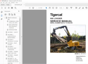
Tigercat FPT N45 Tier 4f ENGINE Service & Repair Manual – PDF DOWNLOAD
Original price was: $87.95.$28.95Current price is: $28.95.
Tigercat FPT N45 Tier 4f ENGINE Service & Repair Manual – PDF DOWNLOAD
Description
Tigercat FPT N45 Tier 4f ENGINE Service & Repair Manual – PDF DOWNLOAD
TABLE OF CONTENTS:
Tigercat FPT N45 Tier 4f ENGINE Service & Repair Manual – PDF DOWNLOAD
NEF 45 TIER 4B Tigercat……………………………………………………………………………………………………. 0
Contents……………………………………………………………………………………………………………… 3
Technical repair manual…………………………………………………………………………………………….. 5
INTRODUCTION…………………………………………………………………………………………………… 7
SYMBOLS – WARNINGS………………………………………………………………………………………….. 9
SYMBOLS – SERVICE OPERATIONS…………………………………………………………………………………. 10
GENERAL WARNINGS……………………………………………………………………………………………. 11
GENERAL WARNINGS REGARDING THE ELECTRICAL SYSTEM……………………………………………………………….. 12
Grounding and screening……………………………………………………………………………………… 13
Optional electrical and mechanical parts installations………………………………………………………….. 14
Conversions between the main units of measurement of the international system and the most commonly used derived sizes…. 15
Power………………………………………………………………………………………………….. 15
Torque…………………………………………………………………………………………………. 15
Revolutions per time unit………………………………………………………………………………… 15
Pressure……………………………………………………………………………………………….. 15
Temperature…………………………………………………………………………………………….. 15
Update data………………………………………………………………………………………………… 16
General information………………………………………………………………………………………………… 17
General information ……………………………………………………………………………………………. 19
Identification plate………………………………………………………………………………………… 21
APPROVAL PLATE……………………………………………………………………………………………… 22
CORRESPONDENCE BETWEEN TECHNICAL CODES AND COMMERCIAL CODES……………………………………………………… 22
TECHNICAL CODES…………………………………………………………………………………………….. 22
COMMERCIAL CODES……………………………………………………………………………………………. 23
ISOMETRIC VIEW……………………………………………………………………………………………… 24
POWER – TORQUE CURVES……………………………………………………………………………………….. 26
Maximum power 125 kW…………………………………………………………………………………….. 26
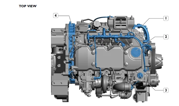
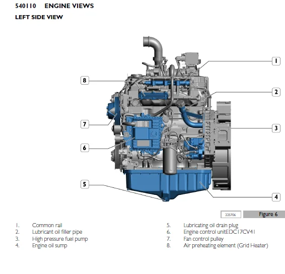
ENGINE VIEWS……………………………………………………………………………………………….. 27
GENERAL CHARACTERISTICS……………………………………………………………………………………… 31
Operating diagrams…………………………………………………………………………………………………. 35
Operating diagrams …………………………………………………………………………………………….. 37
SUPPLY SYSTEM………………………………………………………………………………………………. 39
General information……………………………………………………………………………………… 39
ELECTRICAL SYSTEM……………………………………………………………………………………….. 39
Fuel system sensors………………………………………………………………………………….. 40
System operation…………………………………………………………………………………….. 40
HYDRAULIC SYSTEM………………………………………………………………………………………… 42
Fuel system diagram………………………………………………………………………………….. 44
Checking the overpressure valve on the rail…………………………………………………………….. 45
Checking the mechanical feed pump (ZP18)……………………………………………………………….. 46
Supply system components…………………………………………………………………………………….. 47
Fuel pre-filter…………………………………………………………………………………………. 47
Fuel filter…………………………………………………………………………………………….. 48
Mechanical supply pump…………………………………………………………………………………… 48
Normal operating condition……………………………………………………………………………. 49
Output overpressure condition…………………………………………………………………………. 49
Air bleeding conditions………………………………………………………………………………. 49
BOSCH CP3 high pressure pump……………………………………………………………………………… 50
High-pressure pump internal structure………………………………………………………………….. 51
LUBRICATION CIRCUIT…………………………………………………………………………………………. 52
General information……………………………………………………………………………………… 52
LUBRICATION CIRCUIT COMPONENTS……………………………………………………………………………. 55
Oil pump……………………………………………………………………………………………. 55
Heat exchanger………………………………………………………………………………………. 56
Oil pressure regulator valve………………………………………………………………………….. 57
Engine oil sump……………………………………………………………………………………… 58
Oil filter………………………………………………………………………………………….. 60
OIL VAPOUR RECIRCULATION SYSTEM………………………………………………………………………………. 61
General information……………………………………………………………………………………… 61
Description…………………………………………………………………………………………. 61
OIL VAPOUR RECIRCULATION SYSTEM COMPONENTS…………………………………………………………………. 62
Blow-by filter………………………………………………………………………………………. 62
COOLING CIRCUIT…………………………………………………………………………………………….. 62
General information……………………………………………………………………………………… 62
COOLING CIRCUIT COMPONENTS……………………………………………………………………………….. 64
Water pump………………………………………………………………………………………….. 64
Thermostat………………………………………………………………………………………….. 64
Operation description………………………………………………………………………………… 66
INTAKE AND EXHAUST SYSTEM……………………………………………………………………………………. 67
Turbocharging…………………………………………………………………………………………… 67
Description…………………………………………………………………………………………. 67
turbocharger……………………………………………………………………………………………. 67
Turbocharger actuator……………………………………………………………………………………. 69
Motorised throttle valve…………………………………………………………………………………. 71
EXHAUST GAS POST-TREATMENT SYSTEM(ATS)………………………………………………………………………… 72
General information……………………………………………………………………………………… 72
………………………………………………………………………………………………….. 75
AdBlue specifications………………………………………………………………………………… 78
ATS components………………………………………………………………………………………….. 79
Tank……………………………………………………………………………………………….. 79
AdBlue fluid level gauge control………………………………………………………………………. 80
DeNOx 2.2 (SM) supply module………………………………………………………………………….. 81
Dosing moduleDeNOx 2.5 (DM)…………………………………………………………………………… 82
Engine coolant 3-way valve……………………………………………………………………………. 83
Electric/electronic system………………………………………………………………………………………….. 85
Electric equipment……………………………………………………………………………………………… 87
Location of engine electrical components………………………………………………………………………. 89
E.C.U……………………………………………………………………………………………………… 91
EDC17CV41 electronic control unit…………………………………………………………………………. 91
EDC system operation…………………………………………………………………………………….. 92
Pin out………………………………………………………………………………………………… 95
Pin Out – Engine side………………………………………………………………………………… 95
Pin Out – Vehicle side……………………………………………………………………………….. 98
ENGINE SIDE WIRING…………………………………………………………………………………………..101
Cable on engine………………………………………………………………………………………….101
Wiring-topographic diagram – Engine side……………………………………………………………………104
VEHICLE SIDE WIRING………………………………………………………………………………………….106
Wiring plan-mapping – Vehicle side (Part 1/2)……………………………………………………………….106
Wiring plan-mapping – Vehicle side (Part 2/2)……………………………………………………………….108
Layout TwoBox………………………………………………………………………………………..108
Electronic components………………………………………………………………………………………..109
Electro-injectors………………………………………………………………………………………..109
Beginning of injection………………………………………………………………………………..109
End of injection……………………………………………………………………………………..110
Engine speed sensor on timing system……………………………………………………………………….110
…………………………………………………………………………………………………..110
Engine speed sensor (crankshaft sensor)…………………………………………………………………….111
…………………………………………………………………………………………………..111
Air temperature and boost pressure sensor…………………………………………………………………..112
Engine oil temperature and pressure sensor………………………………………………………………….112
Fuel pressure sensor……………………………………………………………………………………..113
Coolant temperature sensor………………………………………………………………………………..114
Fuel temperature sensor…………………………………………………………………………………..115
High pressure fuel pump dosing unit………………………………………………………………………..117
Preheating resistor (Grid Heater)………………………………………………………………………….118
Motorised throttle valve actuator (Exhaust flap)…………………………………………………………….119
ATS SYSTEM ELECTRICAL COMPONENTS………………………………………………………………………………120
AdBlue liquid temperature and level indicator……………………………………………………………….120
Description………………………………………………………………………………………….120
Functional wiring diagram……………………………………………………………………………..120
technical specifications………………………………………………………………………………121
AdBlue module connector…………………………………………………………………………………..121
Exhaust gas inlet temperature sensor……………………………………………………………………….122
Nitrogen oxide detecting sensor……………………………………………………………………………123
NOx Sensor…………………………………………………………………………………………..127
technical specifications………………………………………………………………………………127
Temperature sensor/air humidity……………………………………………………………………………128
Connector……………………………………………………………………………………………128
Humidity sensor technical specifications………………………………………………………………..129
Technical characteristics of the temperature sensor………………………………………………………129
Ammonia detection control unit (NH3)……………………………………………………………………….130
NH3 ammonia sensor……………………………………………………………………………………….134
Scheduled maintenance……………………………………………………………………………………………….137
SCHEDULED MAINTENANCE……………………………………………………………………………………………139
Introduction………………………………………………………………………………………………..141
Checks and scheduled maintenance procedures…………………………………………………………………….141
CHECKS TO PERFORM DURING PERIOD OF USE…………………………………………………………………………142
Check engine oil level……………………………………………………………………………………142
Checking the engine coolant level………………………………………………………………………….143
Engine visual inspection………………………………………………………………………………….143
Check tension and condition of ancillary belt……………………………………………………………….144
PERIODICAL MAINTENANCE……………………………………………………………………………………….145
Draining the water from the fuel pre-filter…………………………………………………………………145
Engine lubricant oil change……………………………………………………………………………….145
Engine oil filter removal – refitting………………………………………………………………………147
Removal – refitting the fuel filter………………………………………………………………………..148
Removal – Ancillary belt refitting (Component not supplied by FPT)…………………………………………….149
Change blow-by filter…………………………………………………………………………………….150
UNSCHEDULED MAINTENANCE………………………………………………………………………………………150
Tappet clearance adjustment……………………………………………………………………………….150
Change the engine coolant…………………………………………………………………………………153
ATS SYSTEM SCHEDULED MAINTENANCE………………………………………………………………………………….155
Maintenance services schedule for ATS system……………………………………………………………………157
Location of the ATS system filters…………………………………………………………………………157
Replacing the AdBlue filter……………………………………………………………………………….158
Disassembly………………………………………………………………………………………….158
assembly…………………………………………………………………………………………….159
Removal-refitting of the main engine components………………………………………………………………………..161
Removal – refitting of main components…………………………………………………………………………….163
Removal – Ancillary belt refitting (Component not supplied by FPT)………………………………………………..165
Removal – Alternator refitting (Component not supplied by FPT)……………………………………………………165
Removal – refitting of the automatic belt tensioner……………………………………………………………..166
Water pump removal-refitting………………………………………………………………………………….167
Removal – refitting of the thermostat………………………………………………………………………….168
Electric starter motor removal-refitting (Component not supplied by FPT)…………………………………………..169
Engine cable removal-refitting………………………………………………………………………………..171
Removal – refitting of the engine brake………………………………………………………………………..173
Turbocharger removal-refitting………………………………………………………………………………..175
Engine oil filter removal – refitting………………………………………………………………………….180
Heat exchanger removal-refitting………………………………………………………………………………181
Oil sump removal-refitting……………………………………………………………………………………183
Removal – refitting of the fuel pipes………………………………………………………………………….184
Removal – refitting the fuel filter……………………………………………………………………………188
Removal – Refitting vehicle fuel filter mount…………………………………………………………………..189
Removal – refitting of the high pressure pump…………………………………………………………………..191
Common rail removal-refitting…………………………………………………………………………………193
Removal – refitting of the EDC 17 control unit………………………………………………………………….195
Removal – refitting the tappet cover…………………………………………………………………………..198
Removal – refitting of the oil vapour recirculation system (blow-by)………………………………………………199
Removal – refitting the electro-injector wirings………………………………………………………………..200
Removal – refitting of the electro-injectors……………………………………………………………………202
Removal – refitting of the rocker arm unit……………………………………………………………………..205
Removal – Air heater refitting(Grid heater)…………………………………………………………………….209
Intake manifold removal-refitting……………………………………………………………………………..210
Exhaust manifold removal-refitting…………………………………………………………………………….212
Cylinder head removal-refitting……………………………………………………………………………….213
Removal – refitting of the crankshaft drive pulley………………………………………………………………217
Removal – refitting of the crankshaft front cover seal ring………………………………………………………218
Removal – refitting of the engine flywheel……………………………………………………………………..221
Removal – refitting of the crankshaft rear seal ring…………………………………………………………….223
General mechanical overhaul………………………………………………………………………………………….227
General mechanical overhaul ……………………………………………………………………………………..229
General mechanical overhaul of the engine on the bench…………………………………………………………..231
Technical specifications…………………………………………………………………………………………….329
technical specifications…………………………………………………………………………………………331
DATA – INSTALLATION CLEARANCES………………………………………………………………………………..333
TIGHTENING TORQUES…………………………………………………………………………………………..337
Equipment………………………………………………………………………………………………………….343
TOOLS………………………………………………………………………………………………………….345
Safety regulations………………………………………………………………………………………………….355
SAFETY REGULATIONS………………………………………………………………………………………………357
Standard safety precautions…………………………………………………………………………………..359
Accident prevention………………………………………………………………………………………….359
During maintenance…………………………………………………………………………………………..359
Protection of the environment…………………………………………………………………………………360
DESCRIPTION:
Tigercat FPT N45 Tier 4f ENGINE Service & Repair Manual – PDF DOWNLOAD
INTRODUCTION :
This document provides data, specifications, instructions and methods to perform repair interventions on the assembly and its components. Anyhow, this document is addressed to qualified and specialised personnel. Before performing any intervention, check that the document relating to the vehicle model on which the intervention is being performed is available and also make sure that all accident prevention devices, including but not limited to, goggles, helmet, gloves, shoes, as well as work equipment, lifting and transport equipment, etc., are available and efficient, and also make sure that the unit is in safety conditions for intervention.
- Carrying out interventions which fully comply with the indications given here, as well as the use of the specific equipment indicated, ensures repair interventions are carried out correctly, timings are respected and the operator’s safety is safeguarded.
- Each repair intervention must be finalised to the recovery of functionality, efficiency and safety conditions that are provided by FPT. Each intervention on the unit aimed at a modification, alteration or other which has not been authorised by FPT relieves FPT of any liability, and, in particular, where the assembly is covered by a warranty, each intervention will immediately invalidate the warranty.
- FPT declines any liability for repair work. FPT is available to provide any information necessary for the execution of the interventions and to provide instructions for any cases and situations not covered in this publication. The data contained in this issue may not be up-to-date due to possible modifications made by the Manufacturer for technical or commercial reasons, or to adaptations required by laws in force in different countries. In the event of discordance between the information in this publication and the actual assembly, please contact the FPT network before performing any interventions.
- The complete or partial reproduction of the text or illustrations herein is forbidden. Manuals for repairs are split into Sections, each one of which is marked by a numeral; the contents of these sections are indicated in the general table of contents.
- Sections with mechanical contents include technical data, tightening torque collections, tool lists, overhauls at the bench, diagnostics and scheduled maintenance In the electrical/electronic system section there are the descriptions of the electric network and the electronic systems of the assembly, wiring diagrams, electrical characteristics of components and the component codes. The appendix provides a list of the general safety regulations which all operators, whether installers or maintenance technicians, must comply with to prevent any serious injury.
IMAGES PREVIEW OF THE MANUAL:
TIGERCAT FPT N45 TIER 4F ENGINE SERVICE & REPAIR MANUAL – PDF DOWNLOAD:
PLEASE NOTE:
- This is the SAME exact manual used by your dealers to fix your vehicle.
- The same can be yours in the next 2-3 mins as you will be directed to the download page immediately after paying for the manual.
- Any queries / doubts regarding your purchase, please feel free to contact [email protected]
S.V