Toshiba MMD-AP High Static Pressure Duct AC Service Manual PDF
Original price was: $95.00.$16.95Current price is: $16.95.
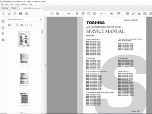
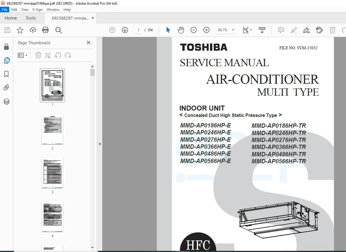
Factory service manual for Toshiba concealed duct high static pressure indoor units MMD-AP0186HP, AP0246HP, AP0276HP, AP0366HP, AP0486HP, and AP0566HP (E and TR models). Comprehensive technical documentation covering R410A multi-type air conditioning systems with complete wiring diagrams, refrigerant cycle schematics, control board specifications, troubleshooting procedures with check codes, sensor characteristics, PCB replacement procedures, and exploded parts diagrams for professional HVAC technicians.
Description
Toshiba MMD-AP High Static Pressure Duct AC Service Manual R410A Multi Type – PDF DOWNLOAD
DESCRIPTION
This comprehensive Toshiba Multi-Type Air Conditioner Service Manual (File No. SVM-15032) provides complete technical documentation for servicing and repairing concealed duct high static pressure indoor units in commercial HVAC installations. This professional-grade manual is essential for qualified HVAC technicians, certified installers, and authorized service personnel working on Toshiba Carrier Corporation R410A multi-type air conditioning systems.
Models Covered
This service manual includes detailed technical information for the following Toshiba concealed duct indoor units:
E-Series Models (European/Standard):
- MMD-AP0186HP-E (5.6 kW cooling / 6.3 kW heating)
- MMD-AP0246HP-E (7.1 kW cooling / 8.0 kW heating)
- MMD-AP0276HP-E (8.0 kW cooling / 9.0 kW heating)
- MMD-AP0366HP-E (11.2 kW cooling / 12.5 kW heating)
- MMD-AP0486HP-E (14.0 kW cooling / 16.0 kW heating)
- MMD-AP0566HP-E (16.0 kW cooling / 18.0 kW heating)
TR-Series Models (Turkey Region):
- MMD-AP0186HP-TR through MMD-AP0566HP-TR (same capacity ratings)
System Type & Application
- Configuration: Concealed duct high static pressure type
- Refrigerant: R410A
- System: Multi-type indoor units for SMMS, SHRM, Mini-SMMS, and SMMS-i systems
- Application: Commercial buildings, offices, retail spaces requiring ducted air distribution
- Manufacturer: Toshiba Carrier Corporation
- Distributed by: AMP Air Conditioning
Technical Specifications Summary
Electrical Characteristics (1-Phase, 50Hz, 230V)
- Power supply range: 220V-240V
- Running current: 0.52A to 1.68A (model dependent)
- Power consumption: 0.085 kW to 0.290 kW
- Starting current: 0.78A to 2.51A
Physical Dimensions:
- Height: 298mm
- Width: 1000mm (AP0186/0246) or 1400mm (AP0276/0366/0486/0566)
- Depth: 750mm
- Weight: 34kg to 43kg (model dependent)
Construction:
- Casing: Zinc hot-dipping steel plate
- Heat exchanger: Finned tube type
- Insulation: Polyethylene foam soundproof/heat-insulating material
Fan System:
- Fan type: Centrifugal fan
- Airflow (High/Med/Low): 800-2,400 m³/h depending on model
- Motor output: 250W to 350W
- External static pressure: 100Pa factory setting
- Adjustable range: 50-200Pa in 7 steps (50, 75, 100, 125, 150, 175, 200Pa)
Refrigerant Connections:
- Gas side: 12.7mm or 15.9mm (model dependent)
- Liquid side: 6.4mm or 9.5mm (model dependent)
Remote Controllers:
- Wired type: TCB-LK801D-E (sold separately)
- Wired type: TCB-LK1401D-E (sold separately)
- Wireless remote controller compatible
Section 1: Specifications
Complete technical specifications table covering:
- Cooling and heating capacity ratings for all models
- Electrical characteristics and power consumption
- Physical dimensions and weight
- Heat exchanger specifications
- Fan motor output and airflow rates
- External static pressure settings (7-step adjustment)
- Connecting pipe dimensions
- Remote controller compatibility
Section 2: Air Ducting Work
- Duct installation guidelines
- Airflow distribution requirements
- Static pressure considerations
- Recommended duct sizing
- Supply and return air configurations
Section 3: Construction Views (External Views)
- Detailed external assembly diagrams
- Component location identification
- Access panel locations
- Mounting bracket positions
- Service access points
- Dimensional drawings with measurements
Section 4: Wiring Diagrams
Complete electrical schematics including:
- Power supply wiring
- Control circuit diagrams
- Remote controller connections
- Sensor wiring layouts
- Communication bus wiring
- Terminal block configurations
- Color-coded wire identification
Section 5: Parts Rating
- Component electrical ratings
- Motor specifications
- Fan motor characteristics
- Capacitor values
- Relay ratings
- Sensor specifications
Section 6: Refrigerant Cycle Diagram
Refrigerant Flow Schematic:
- Liquid side and gas side piping
- Strainer locations
- Capillary tube positioning
- Heat exchanger configuration
- Pulse Motor Valve (PMV) operation
Functional Parts Explanation:
Pulse Motor Valve (PMV) – Connector CN082 (6P, Blue):
- Superheat control in cooling operation
- Undercool control in heating operation
- Refrigerant oil recovery in cooling
- Refrigerant oil recovery in heating
Temperature Sensors:
- TA Sensor – Connector CN104 (2P, Yellow): Indoor suction temperature detection
- TC1 Sensor – Connector CN100 (3P, Brown): PMV superheat control in cooling
- TC2 Sensor – Connector CN101 (2P, Black): PMV undercool control in heating
- TCJ Sensor – Connector CN102 (2P, Red): PMV superheat control in cooling
Section 7: Control Outline
Control Specifications:
Upon Power Supply Reset:
- Outdoor unit identification and control redirection
- Indoor fan speed and air flow direction settings from EEPROM
- Check code clearing if power reset follows a fault
Operation Selection:
- Remote controller command processing
- Operation modes: STOP, FAN, COOL, DRY, HEAT
- Mode transition protocols
Room Temperature Control:
- Adjustment range for wired remote: 18-29°C (cooling/dry and heating)
- Adjustment range for wireless remote: 18-30°C (cooling/dry), 18-29°C (heating)
- Temperature differential control
- Set point management
Section 8: Applied Control and Functions
8-1. Indoor Controller Block Diagrams:
- Wired (simple) remote controller connection configuration
- Wireless remote controller connection setup
- Combined wired and wireless remote controller operation
- Signal flow and communication protocols
8-2. Indoor Print Circuit Board MCC-1631:
- Complete PCB layout and component identification
- Circuit board specifications
- Connector locations and pin assignments
- Jumper settings
8-3. Optional Connector Specifications:
- Detailed pin-out diagrams
- Voltage and signal specifications
- Communication protocol details
- Interface compatibility
8-4. Test Operation Procedures:
- Forced operation mode activation
- Test run sequences
- Performance verification protocols
- Diagnostic test procedures
8-5. DN Code Setting Method:
- Indoor unit function code configuration
- DIP switch settings
- Address assignment procedures
- System configuration codes
8-6. Applied Control Functions:
- Automatic operation mode
- Fan speed control (high, medium, low)
- External static pressure adjustment (7 steps)
- Defrost operation control
- Cold air discharge prevention
- Residual heat elimination
- Timer functions
- Energy-saving features
Section 9: Troubleshooting
9-1. Overview:
- Applicable models: SMMS, SHRM, Mini-SMMS, SMMS-i systems
- Required tools and measuring devices
- Pre-troubleshooting behavior checks
- Normal operation behaviors vs. fault conditions
9-2. Troubleshooting Method:
- Self-diagnosis feature utilization
- Check code analysis procedures
- LCD display interpretation (remote controller)
- 7-segment display reading (outdoor unit interface PCB)
- Fault site identification methodology
9-3. Troubleshooting Based on Remote Controller Display:
- Check code interpretation guide
- Error message analysis
- Display symbol meanings
- Indicator light patterns
9-4. Complete Check Code List:
Error Codes Detected by Indoor Unit:
- E03: Indoor-remote controller periodic communication error
- E04: Indoor-outdoor periodic communication error
- E08: Duplicated indoor address detection
- E10: Indoor inter-MCU communication error
- E18: Header-follower unit periodic communication error
- F01: Heat exchanger temperature sensor TCJ error (open/short circuit)
- F02: Heat exchanger temperature sensor TC2 error (open/short circuit)
- F03: Heat exchanger temperature sensor TC1 error
Indicator Light Patterns:
- Operation LED status (lighting, flashing, off)
- Timer LED status
- Ready LED status
- Alternating flash codes (ALT)
- Simultaneous flash codes (SIM)
Locations to be Checked:
- Sensor connections and wiring
- Control board components
- Communication lines
- Power supply circuits
- Refrigerant system components
9-5. Sensor Characteristics:
- Temperature sensor resistance curves
- Thermistor specifications
- Pressure sensor characteristics
- Calibration data
- Testing procedures
Section 10: P.C. Board Exchange Procedures
10-1. Indoor P.C. Board Replacement:
- Board removal procedures
- Static electricity precautions (ESD protection)
- Connector disconnection sequence
- New board installation steps
- Settings transfer procedures
- Function testing after replacement
- EEPROM data preservation
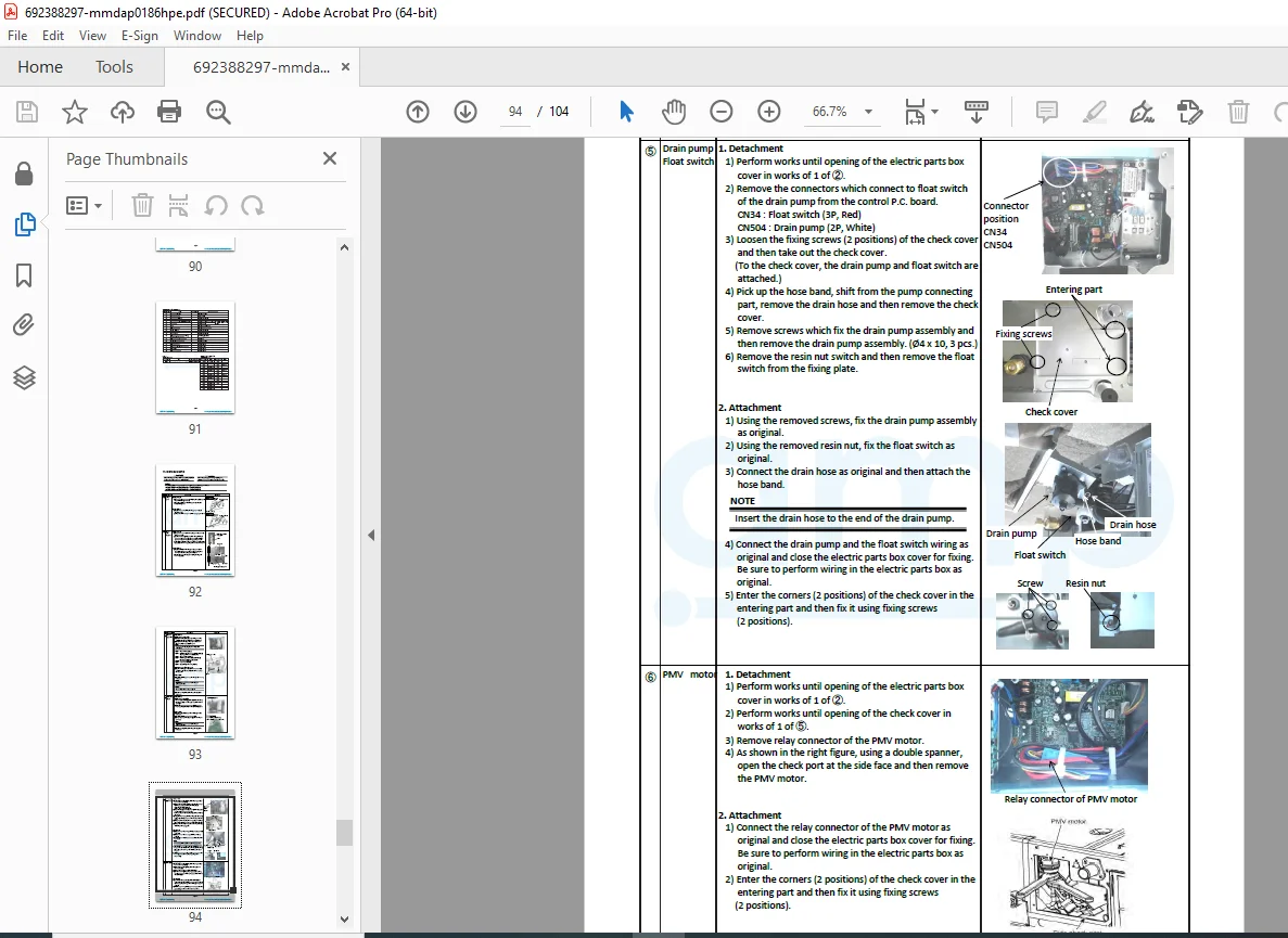
Section 11: Detachments
Complete disassembly procedures with step-by-step instructions:
- Front panel removal
- Air filter access and removal
- Fan unit disassembly
- Motor removal procedures
- Heat exchanger access
- Control board extraction
- Drain pan removal
- Component replacement sequences
- Reassembly procedures
- Torque specifications
Section 12: Exploded Views and Parts List
- Detailed exploded diagrams showing all components
- Part number identification
- Component nomenclature
- Assembly relationships
- Hardware specifications
- Gasket and seal locations
- Fastener types and sizes
- Replacement part ordering information
Key Features & Technical Highlights
✓ R410A Refrigerant System – Latest generation environmentally friendly refrigerant
✓ High Static Pressure Design – 50-200Pa adjustable in 7 steps for extensive ductwork
✓ Multi-Type Compatibility – Works with SMMS, SHRM, Mini-SMMS, and SMMS-i outdoor units
✓ Pulse Motor Valve Control – Precise refrigerant flow management
✓ Advanced Diagnostics – Self-diagnosis with detailed check code system
✓ Centrifugal Fan System – High-efficiency airflow distribution
✓ Polyethylene Foam Insulation – Superior soundproofing and thermal performance
✓ Multiple Control Options – Wired and wireless remote controller compatibility
✓ Commercial Grade Construction – Zinc hot-dipping steel plate casing
✓ Machinery Directive Compliant – Meets EU Directive 2006/42/EC standards
Safety & Qualification Requirements
Qualified Installer Requirements:
- Training in Toshiba Carrier Corporation systems
- Electrical work qualifications per local regulations
- Refrigerant handling certifications
- Height work training (where applicable)
Qualified Service Person Requirements:
- Installation, repair, and maintenance training
- Electrical work certifications
- Refrigerant handling and piping qualifications
- Comprehensive system knowledge
Protective Gear Specifications:
- Protective gloves mandatory
- Safety work clothing required
- Additional protective equipment for special tasks
- ESD protection for electronic component handling
File Details
Manual Name: Toshiba Multi-Type Air Conditioner Service Manual – Concealed Duct High Static Pressure Indoor Units
File Number: SVM-15032
Models Covered: MMD-AP0186HP-E/TR, AP0246HP-E/TR, AP0276HP-E/TR, AP0366HP-E/TR, AP0486HP-E/TR, AP0566HP-E/TR
Refrigerant Type: R410A
Total Pages: 104 pages
PDF Quality: High-quality factory manual (copy-protected)
File Size: 9.4 MB
Format: Searchable PDF (A4 format, 596 x 842 pts)
Publisher: Toshiba Carrier Corporation