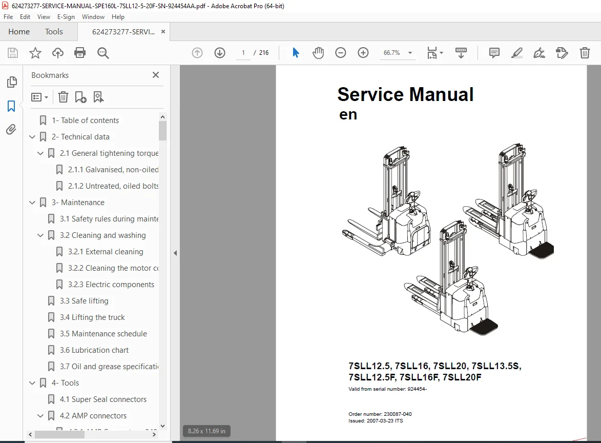
Toyota 7SLL12.5 7SLL16 7SLL20 Service Manual PDF Electric Stacker Forklift
Original price was: $85.00.$28.95Current price is: $28.95.
Official Toyota 7SLL12.5 service manual PDF (2007-03-23). Full troubleshooting Toyota 7SLL16 hydraulic system errors, spare parts Toyota 7SLL20F electric drive motor, maintenance Toyota 7SLL13.5S chassis components, electrical systems Toyota 7SLL16F wiring diagrams, TruckCom diagnostics for 7SLL12.5F-20F from SN 924454-
Description
Toyota 7SLL12.5 7SLL16 7SLL20 Service Manual Electric Stacker Forklift – PDF DOWNLOAD
Description
This is the official Toyota 7SLL Series service manual PDF straight from Toyota Industrial Equipment Europe SARL – the only authorized 2007 release for low-lifter stackers. Covers every detail from safety rules to TruckCom programming, including troubleshooting Toyota 7SLL16 hydraulic system errors, spare parts Toyota 7SLL20F electric drive motor, maintenance Toyota 7SLL13.5S chassis components, and full electrical systems Toyota 7SLL16F wiring diagrams.
TABLE OF CONTENTS (exact bullet-point layout from pages 3–9)
- 1 Table of contents
- 2 Technical data
- 2.1 General tightening torques
- 2.1.1 Galvanised, non-oiled bolts
- 2.1.2 Untreated, oiled bolts
- 2.1 General tightening torques
- 3 Maintenance
- 3.1 Safety rules during maintenance work
- 3.2 Cleaning and washing
- 3.2.1 External cleaning
- 3.2.2 Cleaning the motor compartment
- 3.2.3 Electric components
- 3.3 Safe lifting
- 3.4 Lifting the truck
- 3.5 Maintenance schedule
- 3.6 Lubrication chart
- 3.7 Oil and grease specification
- 4 Tools
- 4.1 Super Seal connectors
- 4.2 AMP connectors
- 4.2.1 AMP Connectors, 040 series
- 4.3 Molex connectors
- 4.4 Grease guns
- 4.5 Other tools
- 5 Chassis – 0000
- 5.1 Support arms
- 5.1.1 General
- 5.1.2 Main components
- 5.1.3 Maintenance
- 5.1.4 Adjusting the support arm width
- 5.1.5 Support arm replacement
- 5.2 Engine suspension
- 5.2.1 Components
- 5.2.2 Disassembly
- 5.2.3 Spring replacement
- 5.3 Platform
- 5.3.1 Components
- 5.3.2 Disassembly
- 5.1 Support arms
- 6 Electric drive motor – 1760
- 6.1 Included components
- 6.2 Disassembly/assembly of the truck motor
- 6.2.1 Disassembly
- 6.2.2 Assembly
- 6.3 Service/repairs
- 6.3.1 Disassembly of the motor
- 6.3.2 Motor installation
- 6.3.3 Cleaning
- 7 Drive unit/gear – 2550
- 7.1 General
- 7.2 Included components
- 7.3 Disassembly of the drive unit from the truck
- 7.4 Assembly of the drive unit in the truck
- 7.5 Oil inspection or changing oil
- 7.5.1 Oil inspection/replenishment
- 7.5.2 Changing oil
- 7.6 Replacing the gasket ring
- 7.6.1 Disassembly
- 7.6.2 Assembly
- 7.7 Leakage from top cover
- 8 Electromagnetic brake – 3370
- 8.1 Main components of the brake
- 8.2 Maintenance
- 8.2.1 Basic adjustment of the play
- 8.2.2 Brake disc replacement
- 9 Electrical steering system – 4300
- 9.1 Electrical steering servo
- 9.1.1 General
- 9.2 Steering servo components
- 9.3 Adjustment
- 9.3.1 Reference sensor
- 9.3.2 Calibration
- Parameter 36
- Parameter 37
- 9.1 Electrical steering servo
- 10 Electrical systems – 5000
- 10.1 General
- 10.1.1 Part numbers
- 10.1.2 Nomenclature
- 10.2 Electrical equipment overview
- 10.2.1 Component placement
- 10.2.2 Component list
- 10.3 Electrical wiring diagram
- 10.3.1 Symbol list
- 10.3.2 Overview
- 10.3.3 Detailed wiring diagram
- 10.4 Functional description
- 10.4.1 Principle of operation
- 10.4.2 Description of steering system
- 10.4.3 Spider expansion unit (SEU)
- 10.4.4 Speed limitation
- 10.4.5 Hour meter and battery condition
- 10.4.6 TLS – Truck log system (optional)
- 10.4.7 ID unit (optional)
- 10.5 Parameters
- 10.5.1 General
- 10.5.2 Viewing parameters – CAN key not connected
- 10.5.3 Viewing parameters – CAN key connected
- 10.5.4 Setting Driver parameters
- 10.5.5 Setting Service parameters
- 10.5.6 Summary of driver parameters
- 10.5.7 Description of driver parameters
- 10.5.8 Summary of service parameters
- 10.5.9 Description of service parameters
- 10.5.10 Configurable “Option” Parameters
- 10.6 Diagnostic and troubleshooting
- 10.6.1 General
- 10.6.2 Fault code history
- 10.6.3 List of fault codes
- 10.6.4 Transistor regulator
- 10.6.5 Built-in Test Function
- 10.6.6 Display test mode
- 10.7 Technical specifications – Curtis 1243
- 10.1 General
- 11 Hydraulic system – 6000
- 11.1 Hydraulic diagram
- 11.1.1 With height-adjustable support arms
- 11.1.2 Without height-adjustable support arms
- 11.2 Main Components
- 11.3 Description
- 11.3.1 Lifting system
- 11.3.2 The PowerTrak system
- 11.3.3 Working pressure
- 11.3.4 Overflow valve
- 11.3.5 Pressure sensor
- 11.1 Hydraulic diagram
- 12 Lift mast – 7000
- 12.1 Mast incline
- 12.2 Main lift chain system
- 12.2.1 Checking the chain setting
- 12.2.2 Chain inspection
- 12.2.3 Cleaning
- 12.2.4 Lubrication
- 13 TruckCom
- 13.1 General
- 13.2 Connection
- 13.3 Layout
- 13.3.1 Main program screen
- 13.3.2 Nodes
- 13.3.3 Icons
- 13.3.4 Tool buttons and menu bar
- 13.3.5 Information window
- 13.3.6 Status bar
- 13.4 Connection function
- 13.5 Disconnection function
- 13.6 Downloading program function
- 13.7 Truck report function
- 13.8 Parameters function
- 13.9 Diagnostics function
- 13.10 Other menu functions
- 13.11 Specifications
- 13.12 Installation
- 14 Destruction instructions
- 14.1 General
- 14.2 Procedure
- 14.3 Abbreviations
- 14.4 Sorting
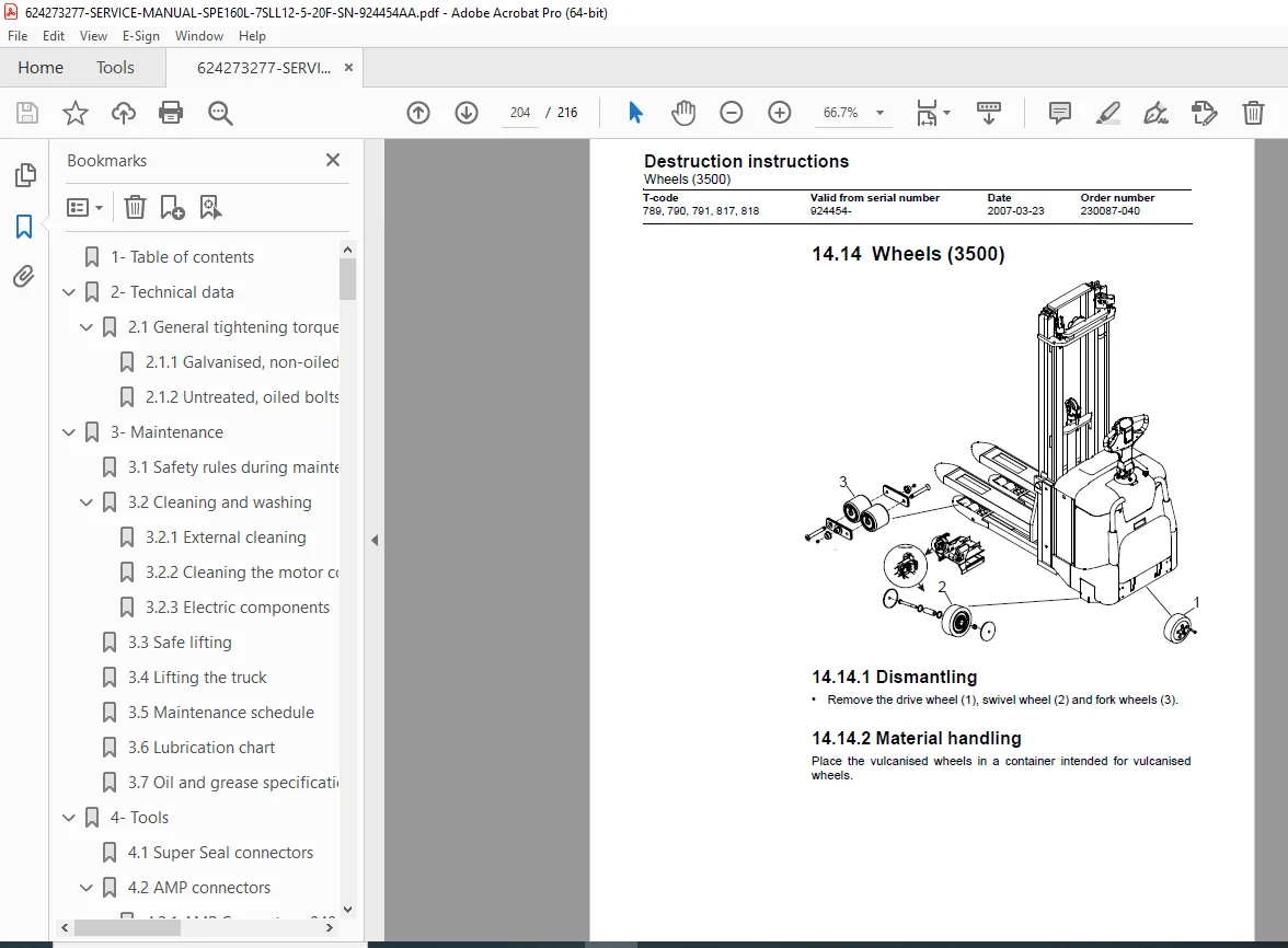
- 14.5–14.24 Component-specific dismantling & material handling
File Details
- Manual Name: Service Manual 7SLL12.5 / 7SLL16 / 7SLL20 / 7SLL13.5S / 7SLL12.5F / 7SLL16F / 7SLL20F (Order No. 230087-040)
- Models Covered: 7SLL12.5, 7SLL16, 7SLL20, 7SLL13.5S, 7SLL12.5F, 7SLL16F, 7SLL20F (Valid from SN 924454-)
- Year: 2007 (Issued 2007-03-23 ITS)
- Manual PDF Quality: Factory-clear scan with exploded views, schematics, torque tables
- No. of Pages: 216