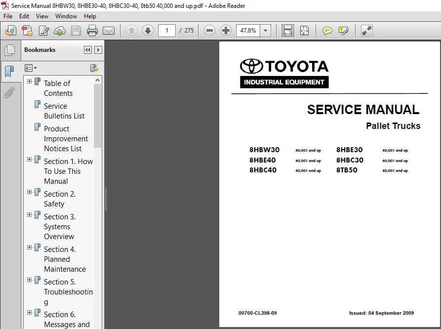
Toyota 8HBW30 8HBE30 8HBE40 8HBC30 8HBC40 8TB50 Service Manual – PDF DOWNLOAD
Original price was: $56.95.$31.95Current price is: $31.95.
Toyota 8HBW30 8HBE30 8HBE40 8HBC30 8HBC40 8TB50 Service Manual – PDF DOWNLOAD
Description
Toyota 8HBW30 8HBE30 8HBE40 8HBC30 8HBC40 8TB50 Service Manual – PDF DOWNLOAD
FILE DETAILS:
Toyota 8HBW30 8HBE30 8HBE40 8HBC30 8HBC40 8TB50 Service Manual – PDF DOWNLOAD
Size : 18.0 MB
Format : PDF
Language : English
Number of Pages: 275 Pages
DESCRIPTION:
Toyota 8HBW30 8HBE30 8HBE40 8HBC30 8HBC40 8TB50 Service Manual – PDF DOWNLOAD
MANUAL DESIGN:
The Toyota Reach Service Manual is designed with the following objectives in mind:
- Provide technical coverage for expected levels of user expertise.
- Anticipate your needs and reduce your decisions regarding maintenance.
- Reduce page flipping through a “one-stop shopping” approach.
The two—line running page header at the top of each page tells you:
- the name of the manual (Toyota Reach Service Manual)
- the current Chapter Title (e.g.. this page How to Use This Manual)
- the current topic (e.g., this page Marmal Design)
- We suggest you get in the habit of turning to the START page first when you use this manual.
- The START page asks a few simple questions to guide you to the proper chapter.
- How to Use This Manual explains the manual format and design and contains the Table of Contents and START page.
- Safety explains warning and caution notes, general safety rules and safety rules for batteries, static, jacking, and welding.
- Systems Overview includes truck specifications and functional overview of the major systems.
- Scheduled Maintenance outlines the recommended schedule of preventive services to keep your truck working most efficiently.
- Troubleshooting is a set of “decision-tree” charts designed to take you from a symptom to a specific sequence of tests in order to isolate a failing component.
- The START TROUBLESHOOTING chart (on page 5—20) will guide you to the individual troubleshooting symptom chart you need.
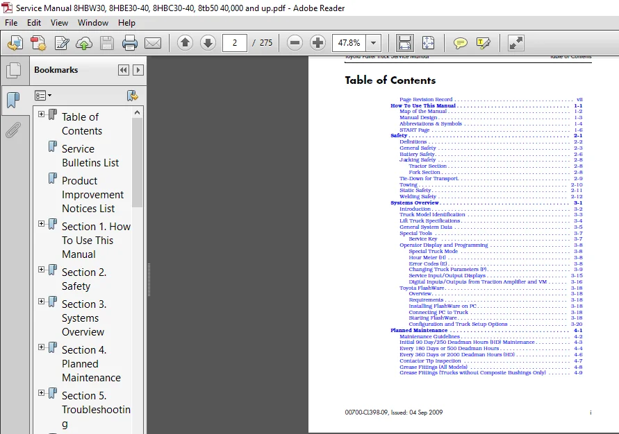
TABLE OF CONTENTS:
Toyota 8HBW30 8HBE30 8HBE40 8HBC30 8HBC40 8TB50 Service Manual – PDF DOWNLOAD
Page Revision Record vii
How To Use This Manual 1-1
Map of the Manual 1-2
Manual Design 1-3
Abbreviations & Symbols 1-4
START Page 1-6
Safety 2-1
Definitions2-2
General Safety 2-3
Battery Safety 2-6
Jacking Safety 2-8
Tractor Section 2-8
Fork Section 2-8
Tie-Down for Transport 2-9
Towing 2-10
Static Safety 2-11
Welding Safety 2-12
Systems Overview 3-1
Introduction 3-2
Truck Model Identification 3-3
Lift Truck Specifications 3-4
General System Data 3-5
Special Tools 3-7
Service Key 3-7
Operator Display and Programming 3-8
Special Truck Mode 3-8
Hour Meter (H) 3-8
Error Codes (E) 3-8
Changing Truck Parameters (P)3-9
Service Input/Output Displays 3-15
Digital Inputs/Outputs from Traction Amplifier and VM 3-16
Toyota FlashWare 3-18
Overview 3-18
Requirements 3-18
Installing FlashWare on PC 3-18
Connecting PC to Truck 3-18
Starting FlashWare 3-18
Configuration and Truck Setup Options 3-20
Planned Maintenance4-1
Maintenance Guidelines 4-2
Initial 90 Day/250 Deadman Hours (HD) Maintenance 4-3
Every 180 Days or 500 Deadman Hours 4-4
Every 360 Days or 2000 Deadman Hours (HD)4-6
Contactor Tip Inspection 4-7
Grease Fittings (All Models) 4-8
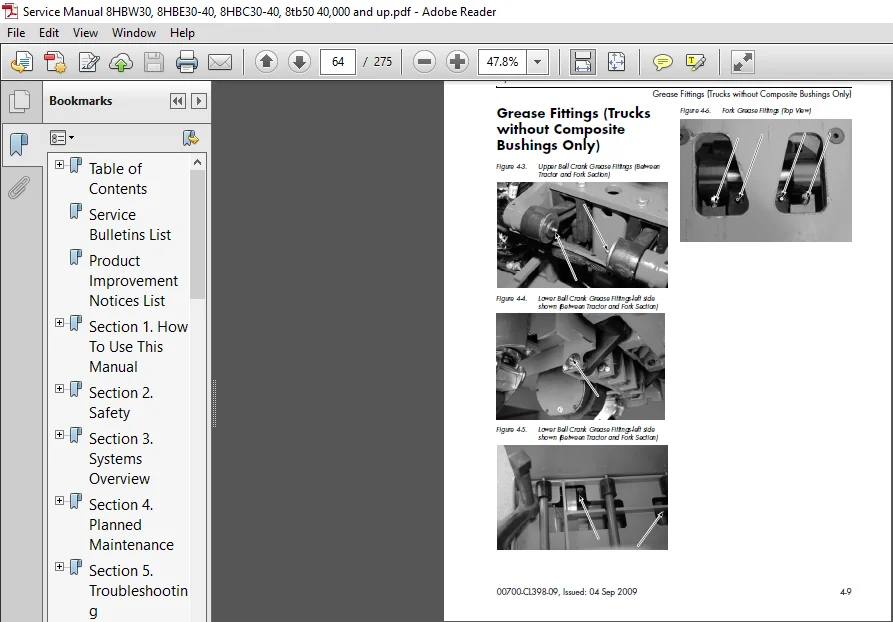
Grease Fittings (Trucks without Composite Bushings Only) 4-9
Table of Contents Toyota Pallet Truck Service Manual
ii 00700-CL398-09, Issued: 04 Sep 2009
Troubleshooting 5-1
How to Use This Section 5-2
Troubleshooting Flowcharts 5-3
TS1: START TROUBLESHOOTING 5-3
GEN1: General Troubleshooting5-4
END1: End of Troubleshooting Procedure 5-5
Electrical Troubleshooting Guidelines 5-6
Troubleshooting the CAN Bus 5-6
Shorts to Frame Test 5-8
Fuses 5-11
Test/Inspection 5-11
DC Electric Motors 5-12
DC Motor Types 5-12
Inspection 5-12
Service5-12
Open Circuit Motor Test 5-14
Grounded Motor Test 5-15
Short-Circuited Armature 5-15
Short-Circuited Winding 5-15
AC Electric Motors 5-16
AC Motor Type 5-16
Open Winding 5-16
Shorted Winding 5-16
Hydraulic Troubleshooting Guidelines 5-17
Symptom Tables: Lift/Lower System 5-18
Symptom Tables: Travel (Forward/Reverse) System 5-21
Symptom Tables: Wiring System 5-26
Messages and Codes 6-1
List of Messages and Codes 6-2
Traction Amplifier LED Diagnostics6-3
Traction Amplifier Flash Codes 6-4
Caution and Error Codes 6-6
Caution Codes 6-7
Error Codes 6-21
Component Procedures 7-1
List of Component Procedures by Truck System7-2
Component Locator Photos 7-5
Steering and Controls 7-9
Control Handle – Model 8HBW30 7-10
Control Handle Disassembly 7-11
Changing Horn Button/Switch7-11
Changing Lift/Lower Button 7-12
Changing Push Button 7-12
Spring-Loaded Handle Design 7-13
Removal 7-13
Installation 7-14
Return Spring Adjustment 7-14
Fixed-Position Handle Design – Models 8HBC30/40 and 8TB50 7-16
Removal 7-16
Installation 7-16
Toyota Pallet Truck Service Manual Table of Contents
00700-CL398-09, Issued: 04 Sep 2009 iii
Control Handle Assemblies – Models 8HBE, 8HBC and 8TB50 7-17
Changing Horn Button/Switch 7-21
Changing Lift/Lower Switch Activator 7-22
Changing the Push Button 7-22
Changing the Jog Trigger Switch 7-23
Changing the Jog Trigger and Spring 7-23
Drive and Brake 7-25
Drive Unit 7-26
Removal 7-26
Steering Bearing 7-27
Removal 7-27
Installation 7-27
Gear Assembly 7-28
Checking the Gears 7-31
Adjusting Tooth Pattern of Drive Unit 7-31
Installation 7-32
Drive Housing Lubrication 7-33
Drive Wheel 7-34
Removal 7-34
Cushion Tire Replacement 7-34
Caster Adjustment 7-36
Casters (without Springs) 7-37
Caster Removal 7-37
Wheel Replacement 7-37
Caster Assembly 7-37
Caster Installation 7-38
Casters (Spring-Loaded) 7-39
Removal 7-39
Wheel Replacement 7-39
Caster Disassembly 7-40
Caster Assembly 7-41
Wheel Installation 7-41
Caster Installation 7-41
Brake 7-43
Spring-Loaded Handle 7-43
Removal 7-43
Installation 7-43
Checking the Gap7-44
Replacing the Rotor 7-44
Electrical Components 7-45
Battery 7-46
With Battery Gates and Rollers (Optional)7-46
Battery Gates (Optional) 7-46
Battery Rollers (Optional) 7-46
Without Battery Gates and Rollers 7-46
Battery Exterior Cleaning 7-47
Testing, Charging, and Maintenance 7-47
Maintenance-Free Batteries 7-48
Storage 7-48
Power Cables 7-49
Table of Contents Toyota Pallet Truck Service Manual
iv 00700-CL398-09, Issued: 04 Sep 2009
Wiring Harness 7-51
Terminology 7-51
Inspection 7-51
Repair7-51
Soldering Procedures 7-52
AMP Water-Resistant Connectors 7-53
Pin Extraction 7-53
Pin Insertion 7-54
Seals 7-54
AMP Harness/Traction Amplifier Connector 7-56
Connector Components 7-56
Disassembly (Contact Removal) 7-56
Contact Insertion 7-56
Assembly 7-56
Testing7-58
Brake Potentiometer (VR1) 7-59
Removal 7-59
Installation 7-59
Lift-Limit Switch (SW8) 7-60
Adjustment 7-60
Grab Rail Switches – Model 8HBE30/40 7-61
Removal 7-61
Installation 7-61
Hydraulic Solenoids 7-62
Jog Pick Solenoid – Model 8HBE30/40 Option7-63
Removal 7-63
Installation 7-64
Jog Pick Solenoid Switch/Spring 7-64
Jog Pick Canister 7-64
Traction Amplifier 7-67
Removal 7-67
Installation 7-67
Programming 7-68
Motors, General 7-69
Terminal Nuts 7-69
Traction Motor 7-70
Removal 7-70
Installation 7-72
Lift Motor 7-74
General Data 7-74
Removal 7-74
Installation 7-74
Hydraulic Components 7-77
Hydraulic Components 7-78
General Guidelines7-78
Hydraulic Fluid 7-79
Checking Hydraulic Fluid Level 7-79
Hydraulic Unit 7-80
Removal 7-80
Installation 7-80
Toyota Pallet Truck Service Manual Table of Contents
00700-CL398-09, Issued: 04 Sep 2009 v
Hydraulic Reservoir 7-81
Removal 7-81
Installation 7-81
Filter Screen and Suction Tube 7-82
Removal 7-82
Installation 7-82
Hydraulic Pump 7-83
Installation 7-83
Adjusting Hydraulic Pump Relief Valve Pressure 7-84
Checking Relief Valve Setting7-84
Alternate Method Using Rated Load on Pallets 7-84
Hydraulic Ram 7-86
Inspection 7-86
Removal 7-86
Installation 7-88
Hydraulic Cylinder Seals 7-90
Disassembly 7-90
Assembly 7-91
Mast 7-93
Top Linkage Subassembly 7-94
Removal 7-94
Installation 7-95
Pull Rod Subassembly 7-97
Removal 7-97
Installation 7-98
Load Wheel Suspension – Model 8TB50 7-100
Removal 7-100
Installation 7-101
Fork Height Adjustment 7-102
Measurement 7-102
Adjustment 7-102
Options 7-105
Cold Storage Conditioning 7-106
Theory of Operation 8-1
Definitions8-2
Acceleration Rate 8-2
Brake Lever Potentiometer (VR1)
(Models with Fixed Position Handles) 8-2
Brake (Deadman) Switch (Models with Spring-Loaded Handle) 8-2
Continuity 8-2
Controller Area Network (CAN)8-2
Current Limiting 8-2
Deceleration (Neutral Braking)8-2
Emergency Reverse (Models 8HBW30 and 8HBE30 or 8HBE40) 8-3
Fault Codes 8-3
High Pedal Disable (HPD) 8-3
Jog Speed 8-3
Open Circuit 8-3
Overvoltage Cutoff8-3
PIN-Key Code 8-3
Pulse Width Modulation 8-3
Ramp Shape 8-3
Table of Contents Toyota Pallet Truck Service Manual
vi 00700-CL398-09, Issued: 04 Sep 2009
Regenerative Braking 8-3
Sequencing Delay 8-4
Short Circuit or “Short” 8-4
Speed Limiting 8-4
Static Return to Off (SRO) 8-4
Thermal Cutback (Traction Amplifier) 8-4
Throttle Map 8-5
Truck Off Delay (Keypad only) 8-5
Undervoltage Cutoff8-5
VM (Vehicle Manager) 8-5
Traction System 8-6
Vehicle Manager (VM) 8-6
Traction Amplifier (TA) 8-6
Battery Plugged In 8-6
Key Switch ON and M1 Energized 8-6
Travel Request, Tractor-First 8-7
Travel Request, Forks-First 8-7
Strip Curtain Bypass (Model 8HBE30/40 only) 8-7
Emergency Reverse (Model 8HBW30 and 8HBE30/40) 8-8
Jog Mode 8-8
Jog Pick Mode 8-9
Lift/Lower System 8-10
Lift 8-10
Lower 8-10
Pinout Matrix 8-11
Appendix A-1
Lubrication Equivalency Chart A-2
Thread Adhesives, Sealants, and Lubricants A-3
Component Specific Service/Torque Chart A-4
Torque Chart – Standard (Ferrous)A-6
Torque Chart – Standard (Brass) A-7
Torque Chart – MetricA-8
Torque Chart – Thread-Forming Screws A-9
Decimal Equivalent Chart A-10
Standard/Metric Conversions A-12
List of Electrical Symbols A-14
Schematics A-17
Electrical SchematicsA-19
Power Distribution Diagram A-25
Hydraulic SchematicA-26
Index I-1
TOYOTA 8HBW30 8HBE30 8HBE40 8HBC30 8HBC40 8TB50 SERVICE MANUAL – PDF DOWNLOAD:
IMAGES PREVIEW OF THE MANUAL:
PLEASE NOTE:
- This is the same manual used by the DEALERSHIPS to SERVICE your vehicle.
- The manual can be all yours – Once payment is complete, you will be taken to the download page from where you can download the manual. All in 2-5 minutes time!!
- Need any other service / repair / parts manual, please feel free to contact us at heydownloadss @gmail.com . We may surprise you with a nice offer