Toyota 8HBW30 8HBE40 8HBC40 8HBE30 8HBC30 8TB50 Pallet Trucks Service Manual 00700-CL398-07 – PDF DOWNLOAD
$28.95
Toyota 8HBW30 8HBE40 8HBC40 8HBE30 8HBC30 8TB50 Pallet Trucks Service Manual 00700-CL398-07 – PDF DOWNLOAD
8HBW30 36,001 and up 8HBE30 36,001 and up
8HBE40 36,001 and up 8HBC30 36,001 and up
8HBC40 36,001 and up 8TB50 36,001 and up
Description
Toyota 8HBW30 8HBE40 8HBC40 8HBE30 8HBC30 8TB50 Pallet Trucks Service Manual 00700-CL398-07 – PDF DOWNLOAD
FILE DETAILS:
Toyota 8HBW30 8HBE40 8HBC40 8HBE30 8HBC30 8TB50 Pallet Trucks Service Manual 00700-CL398-07 – PDF DOWNLOAD
Language : English
Pages : 258
Downloadable : Yes
File Type : PDF
DESCRIPTION:
Toyota 8HBW30 8HBE40 8HBC40 8HBE30 8HBC30 8TB50 Pallet Trucks Service Manual 00700-CL398-07 – PDF DOWNLOAD
8HBW30 36,001 and up 8HBE30 36,001 and up
8HBE40 36,001 and up 8HBC30 36,001 and up
8HBC40 36,001 and up 8TB50 36,001 and up
Manual Design:
The Toyota Pallet Truck Service Manual is designed with the following objectives in mind:
- Provide technical coverage for expected levels of user expertise
- Anticipate your needs and reduce your decisions regarding maintenance
- Reduce page flipping through a “one-stop shopping” approach
The two-line running page header at the top of each page tells you:
- Name of the manual
(Toyota Pallet Truck Service Manual) - Current Chapter Title
(for example, this page How to Use This Manual) - Current topic
(for example, this page Manual Design)
We suggest you get in the habit of turning to the START page first when you use this manual.
• The START page asks a few questions to guide you to the correct section.
- How to Use This Manual explains the manual format and design and contains the Table of Contents and START page.
- Safety explains warning and caution notes, general safety rules and safety rules for batteries, static, jacking, and welding.
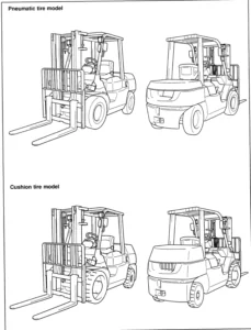
- Systems Overview includes truck specifications and theory of operation information.
- Planned Maintenance outlines the recommended schedule of preventive services to keep your truck working most efficiently.
- Troubleshooting is a set of “decision-tree” charts and tables designed to take you from a symptom to a specific sequence of tests in order to isolate a failing component.
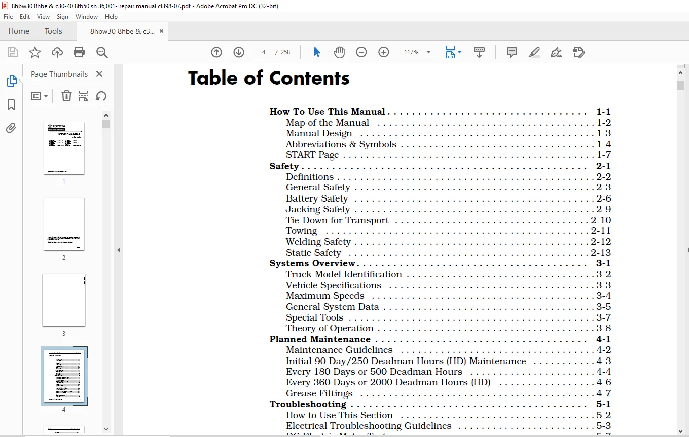
TABLE OF CONTENTS:
Toyota 8HBW30 8HBE40 8HBC40 8HBE30 8HBC30 8TB50 Pallet Trucks Service Manual 00700-CL398-07 – PDF DOWNLOAD
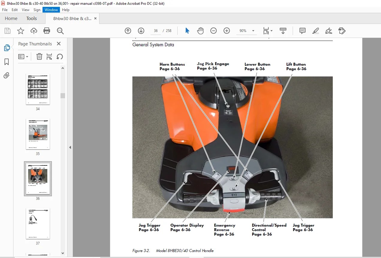
Front Cover.................................................................................................  1
Table of Contents...........................................................................................  4
Section 1. How To Use This Manual ..........................................................................  7
	Map of the Manual ......................................................................................  8
	Manual Design ..........................................................................................  9
	Abbreviations & Symbols ................................................................................ 10
	START Page ............................................................................................. 13
Section 2. Safety .......................................................................................... 16
	Definitions ............................................................................................ 17
	General Safety ......................................................................................... 18
	Battery Safety ......................................................................................... 21
	Jacking Safety ......................................................................................... 24
	Tie-Down for Transport ................................................................................. 25
		Figure 2-1. Tie-Down for Transport ................................................................. 25
	Towing ................................................................................................. 26
	Welding Safety ......................................................................................... 27
	Static Safety .......................................................................................... 28
		Figure 2-2. Anti-Static Kit (P/N 00590-04849-71) With Wrist Strap and Mat .......................... 28
Section 3. Systems Overview ................................................................................ 31
	Truck Model Identification ............................................................................. 32
	Vehicle Specifications ................................................................................. 33
	Maximum Speeds ......................................................................................... 34
		Tractor First ...................................................................................... 34
		Forks First ........................................................................................ 34
	General System Data .................................................................................... 35
		Figure 3-1. Model 8HBE30/40 (Long-John Forks Shown) ................................................ 35
		Figure 3-2. Model 8HBE30/40 Control Handle ......................................................... 36
	Special Tools .......................................................................................... 37
		Service Key ........................................................................................ 37
			Figure 3-3. Service Key ........................................................................ 37
	Theory of Operation .................................................................................... 38
		Vehicle Manager (VM) ............................................................................... 38
		Traction Power Amplifier (TPA) ..................................................................... 38
		Traction System .................................................................................... 38
		Emergency Reverse (Model 8HBW30 and 8HBE30/40) ..................................................... 39
		Strip Curtain Bypass (Model 8HBE30/40 only) ........................................................ 39
		Lift/Lower System .................................................................................. 40
		Jog Pick Mode ...................................................................................... 40
		Model 8HBE30/40 only ............................................................................... 41
		Manual Jog Pick .................................................................................... 41
Section 4. Planned Maintenance ............................................................................. 44
	Maintenance Guidelines ................................................................................. 45
	Initial 90 Day/250 Deadman Hours (HD) Maintenance ...................................................... 46
	Every 180 Days or 500 Deadman Hours .................................................................... 47
	Every 360 Days or 2000 Deadman Hours (HD) .............................................................. 49
	Grease Fittings ........................................................................................ 50
		Figure 4-1. Caster Grease Fittings ................................................................. 50
		Figure 4-2. Upper Bell Crank Grease Fittings (Between Tractor and Fork Section) .................... 50
		Figure 4-3. Lower Bell Crank Grease Fittings-left side shown (Between Tractor and Fork Section) .... 50
		Figure 4-4. Load Wheel Grease Fittings and Fork Grease Fittings (Top View-8K trucks) ............... 51
Section 5. Troubleshooting ................................................................................. 53
	How to Use This Section ................................................................................ 54
	Electrical Troubleshooting Guidelines .................................................................. 55
		Troubleshooting the CAN Bus ........................................................................ 55
		Checking for Shorts from Battery to Truck Frame .................................................... 57
		Checking for Shorts from Components to Truck Frame ................................................. 58
	DC Electric Motor Tests ................................................................................ 59
		DC Motor Types ..................................................................................... 59
			Figure 5-1. Motor Circuits ..................................................................... 59
		Open Circuit Motor Test ............................................................................ 59
		Grounded Motor Test ................................................................................ 59
		Short-Circuited Winding ............................................................................ 60
		Short-Circuited Armature ........................................................................... 60
	AC Electric Motor Tests ................................................................................ 61
		Figure 5-2. AC Traction Motor circuits ............................................................. 61
		AC Motor Type ...................................................................................... 61
		Open Winding ....................................................................................... 61
		Shorted Winding .................................................................................... 61
	Hydraulic Troubleshooting Guidelines ................................................................... 62
	Definitions ............................................................................................ 63
		Figure 5-3. Brake (Deadman) Switch and Brake Actuation ............................................. 63
	List of Electrical Symbols ............................................................................. 67
	Operator Display and Programming ....................................................................... 69
		Figure 5-4. Operator Display ....................................................................... 69
		Special Truck Mode ................................................................................. 69
		Hour Meter (H) ..................................................................................... 69
		Error Codes (E) .................................................................................... 69
		Changing Truck Parameters (P) ...................................................................... 70
	Service Input/Output Displays .......................................................................... 75
		Figure 5-5. Service Key Connection Point ........................................................... 75
		Figure 5-6. Operator Display ....................................................................... 75
		Digital Inputs/Outputs from Traction Power Amplifier and VM ........................................ 76
	Traction Power Amplifier LED Diagnostics ............................................................... 78
		Figure 5-7. Traction Power Amplifier Status Indicator LED .......................................... 78
	Traction Power Amplifier Flash Codes ................................................................... 79
	Troubleshooting Flowcharts ............................................................................. 81
	Caution and Error Codes ................................................................................ 85
		Figure 5-8: Operator Display ....................................................................... 85
		Caution Codes ...................................................................................... 85
		Error Codes ........................................................................................ 97
	Symptom Tables: Lift/Lower System ......................................................................107
	Symptom Tables: Travel (Forward/Reverse) System ........................................................111
	Symptom Tables: Wiring System ..........................................................................120
	Pinout Matrix ..........................................................................................121
Section 6. Component Procedures ............................................................................136
	List of Component Procedures ...........................................................................137
	Component Locator Photos ...............................................................................140
		Figure 6-1. Inside Tractor, Rear View ..............................................................140
		Figure 6-2. Inside Tractor, Right Side .............................................................141
	Tractor Cover ..........................................................................................142
		Figure 6-3. Cover Handle Hold Locations ............................................................142
	Battery ................................................................................................143
		With Battery Gates and Rollers (Optional) ..........................................................143
		Battery Gates (Optional) ...........................................................................143
		Battery Rollers (Optional) .........................................................................143
		Without Battery Gates and Rollers ..................................................................143
		Battery Exterior Cleaning ..........................................................................144
			Figure 6-4. Battery Filler Plugs and Vent Holes ................................................144
		Testing, Charging, and Maintenance .................................................................145
		Maintenance-Free Batteries .........................................................................145
		Storage ............................................................................................145
	Power Cables ...........................................................................................146
	Wiring Harness .........................................................................................147
	Fuses ..................................................................................................149
		Figure 6-5. Fuse Location ..........................................................................149
	Switches (General) .....................................................................................150
	Key Switch (SW1) .......................................................................................151
		Figure 6-6. Key Switch Location ....................................................................151
	Brake (Deadman) Switch (SW2) ...........................................................................152
		Figure 6-7. Brake (Deadman) Switch, 8HBW30 and 8HBE30 or 8HBE40 ....................................152
		Figure 6-8. Brake (Deadman) Switch Active, 8HBW30 and 8HBE30 or 8HBE40 .............................152
	Lift-Limit Switch (SW8) ................................................................................154
		Figure 6-9. Lift-Limit Switch ......................................................................154
	Grab Rail Switches .....................................................................................155
		Model 8HBE30/40 Only ...............................................................................155
			Figure 6-10. Grab Rail Switch Removal, Left Side ...............................................155
			Figure 6-11: Grab Rail Switch Removal, Right Side ..............................................155
	Hydraulic Solenoids ....................................................................................156
		Figure 6-12. Hydraulic Solenoids (typical unit) ....................................................156
	Jog Pick Solenoid ......................................................................................157
		Model 8HBE30/40 (Optional) .........................................................................157
			Figure 6-13. Socket Head Cap Screws ............................................................157
			Figure 6-14. Removed Solenoid Mechanism ........................................................157
		Jog Pick Solenoid Switch ...........................................................................157
		Canister ...........................................................................................158
			Figure 6-15. Canister Spacing ..................................................................158
	Horn ...................................................................................................159
		Figure 6-16. Horn Location .........................................................................159
	Traction Power Amplifier ...............................................................................160
		Figure 6-17. Traction Power Amplifier Location .....................................................160
		Figure 6-18. Removing the Traction Power Amplifier .................................................160
	AMP Harness/Traction Power Amplifier Connector .........................................................162
		Connector Components ...............................................................................162
			Figure 6-19. JP1 Connector Components ..........................................................162
			Figure 6-20. AMP JP1 Connector .................................................................162
			Figure 6-21. Contact Insertion .................................................................163
			Figure 6-22. Wedge Lock Latches ................................................................163
			Figure 6-23. Wedge Lock Flush With Housing .....................................................164
	Contactors .............................................................................................165
		Figure 6-24. Disconnecting Main Contactor ..........................................................165
		Main Contactor .....................................................................................165
			Figure 6-25. Removing Top Cover ................................................................165
			Figure 6-26. Removing Brass Lock Nuts ..........................................................166
			Figure 6-27. Removing the Fixed Contacts .......................................................166
			Figure 6-28. Installing Fixed Contacts .........................................................166
			Figure 6-29. Main Contactor Components .........................................................166
			Figure 6-30. Installing the Main Contactor .....................................................167
	Control Handle Assembly ................................................................................168
		Spring-Loaded Handle Design - Models 8HBW30 and 8HBE30 or 8HBE40 ...................................168
			Figure 6-31. Control Handle Base Cover Removal .................................................168
			Figure 6-32. Control Handle Wire Harness .......................................................168
			Figure 6-33. Remove Jam Nut at Coast Link ......................................................168
			Figure 6-34: Return Spring Rod Removal .........................................................169
		Return Spring Adjustment ...........................................................................169
			Figure 6-35. Return Spring Adjustment ..........................................................169
		Fixed-Position Handle Design - Models 8HBC30/40 and 8TB50 ..........................................170
	Control Handle .........................................................................................171
		Figure 6-36. Handle and Control Head Assembly ......................................................171
		Figure 6-37. Control Head Assembly -Exploded View ..................................................172
		Control Head Removal ...............................................................................173
			Figure 6-38. Horn Button Removal ...............................................................174
			Figure 6-39. Lift/Lower Button Removal .........................................................174
			Figure 6-40. Push Button Removal ...............................................................174
			Figure 6-41. Handle with Jog Pick Option .......................................................175
	Brake ..................................................................................................176
		Spring-Loaded Handle - Models 8HBW30 and 8HBE30 or 8HBE40 ..........................................176
			Figure 6-42. Brake Adjustment, location ........................................................176
			Figure 6-43: Brake Adjusting Screw .............................................................176
			Figure 6-44. Brake Drum With Control Handle and Brake Shield Removed ...........................177
			Figure 6-45. Brake Adjusting Screw .............................................................177
			Figure 6-46. Brake Adjusting Rod (Installed) ...................................................177
		Fixed-Position Handle - Models 8HBC30/40 and 8TB50 .................................................178
	Motors, General ........................................................................................180
		Terminal Nuts ......................................................................................180
			Figure 6-47. Traction Motor Terminal Connections ...............................................180
			Figure 6-48. Lift and Aux Motor Terminal Nuts ..................................................180
	Traction Motor .........................................................................................181
		Figure 6-49. Control Handle Base Cover Removal .....................................................181
		Figure 6-50. Control Handle Mounting Frame Removal .................................................181
		Figure 6-51. Traction Motor Power Cables ...........................................................181
		Figure 6-52. Traction Motor Removal ................................................................182
		Figure 6-53. Drive Unit Pinion Gear ................................................................182
		Figure 6-54. Main Case Location ....................................................................182
		Figure 6-55. Traction Motor Installation ...........................................................183
	AC Motor Service .......................................................................................184
		AC Motor Temperature Sensor ........................................................................184
	Drive Unit .............................................................................................186
		Figure 6-56. Drive Unit Fill Plug ..................................................................186
		Figure 6-57. Drive Unit Drain Plug .................................................................186
		Figure 6-58. Drive Unit Mounting (Traction Motor Removed) ..........................................186
		Steering Bearing ...................................................................................187
			Figure 6-59. Drive Unit (Shown installed in Tractor Frame) .....................................187
			Figure 6-60. Drive Unit Bottom View ............................................................187
			Figure 6-61. Drive Unit, Steering Bearing Removed ..............................................187
			Figure 6-62. Steering Bearing Locating Groove ..................................................187
			Figure 6-63. Main Case Cover, Six Hole-Type, Installed .........................................188
			Figure 6-64. Gear Housing and Cover ............................................................188
			Figure 6-65. Lower Drive Unit, Cross-Sectional View, Model 8HBW30 and 8HBE30 or 8HBE40 .........189
		Gear Assembly ......................................................................................190
		Checking the Gears .................................................................................191
			Figure 6-66. Drive Unit Gear Tooth Pattern .....................................................191
			Figure 6-67. Drive Unit Mounting Location in Frame .............................................192
			Figure 6-68. Drive Unit Installed In Frame .....................................................192
			Figure 6-69. Drive Unit Shimming Locations .....................................................192
			Figure 6-70. Drive Unit Drain Plug .............................................................193
		Drive Housing Lubrication ..........................................................................193
			Figure 6-71. Drive Unit Fill Level Dipstick ....................................................193
			Figure 6-72. Drive Unit Drain Plug .............................................................193
	Drive Wheel ............................................................................................195
		Figure 6-73. Drive Wheel and Tire ..................................................................195
		Figure 6-74. Cushion Tire Replacement ..............................................................195
	Casters (Torsion) ......................................................................................198
		Figure 6-75. Removing Caster Wheel Assembly ........................................................198
		Caster Removal .....................................................................................198
			Figure 6-76. Caster Assembly, Disassembled .....................................................198
		Wheel Replacement ..................................................................................198
			Figure 6-77. Caster Assembly, Assembled ........................................................199
		Caster Assembly ....................................................................................199
		Caster Installation ................................................................................199
			Figure 6-78. Securing Caster To Tractor ........................................................199
	Casters (Spring-Loaded) ................................................................................200
		Figure 6-79. Removing Spring-Loaded Caster .........................................................200
		Removal ............................................................................................200
		Wheel Replacement ..................................................................................200
			Figure 6-80. Removing Axle Shaft ...............................................................200
			Figure 6-81. Removing Tension Pin ..............................................................200
			Figure 6-82. Removed Wheel and Shims ...........................................................201
			Figure 6-83. Compressing Caster Springs ........................................................201
		Caster Disassembly .................................................................................201
			Figure 6-84. Relieving Pivot Tension ...........................................................201
			Figure 6-85. Removing Pivot Pin Retainer Screw .................................................201
			Figure 6-86. Removing Pivot Pin ................................................................202
			Figure 6-87. Separated Caster ..................................................................202
		Caster Assembly ....................................................................................202
			Figure 6-88. Removing Bolts from Springs .......................................................202
			Figure 6-89. Installing New Wheel ..............................................................202
		Wheel Installation .................................................................................203
			Figure 6-90. Installing Axle Shaft .............................................................203
			Figure 6-91. Installing Tension Pin ............................................................203
			Figure 6-92. Caster, Shims and Mounting Bolts ..................................................203
		Caster Installation ................................................................................203
			Figure 6-93. Securing Caster To Tractor ........................................................203
	Load Wheels ............................................................................................204
		Figure 6-94. Removing Tension Pin ..................................................................204
		Models 8HBW30, 8HBE30/40 and 8HBC30/40 .............................................................204
			Figure 6-95. Removing Axle From Load Arm Casting ...............................................204
			Figure 6-96. Removed Load Wheel and Components .................................................204
		Model 8TB50 ........................................................................................205
			Figure 6-97. Model 8TB50 Load Wheel Suspension-Exploded View ...................................205
		Load Wheel Suspension (Optional) ...................................................................206
			Figure 6-98. Model 8TB50 Optional Load Wheel Suspension-Exploded View ..........................206
	Pallet Entry Sliders ...................................................................................207
		Figure 6-99. Replacing Pallet Entry Slider (6000 lb. Standard Model Shown) .........................207
	Fork Height Adjustment .................................................................................208
		Figure 6-100. Fork Height Adjustment at Lower Bell Crank ...........................................208
		Measurement ........................................................................................208
		Adjustment .........................................................................................208
	Hydraulic Components ...................................................................................210
		General Guidelines .................................................................................210
			Figure 6-101. Hydraulic Unit (typical shown) ...................................................210
	Hydraulic Fluid ........................................................................................211
		Figure 6-102. Hydraulic Connections ................................................................211
	Adjusting Hydraulic Pump Relief Valve Pressure .........................................................212
		Figure 6-103. Checking Relief Valve Pressure .......................................................212
		Relief Valve Settings ..............................................................................212
		Check Valve ........................................................................................213
	Hydraulic Ram ..........................................................................................214
		Figure 6-104. Blocking Fork Section For Ram Removal ................................................214
		Figure 6-105. Removing Lower Bell Crank Pins .......................................................214
		Figure 6-106. Disconnecting Upper Clevis Brackets ..................................................215
		Figure 6-107. Hydraulic Ram Area, Forks Removed ....................................................215
		Figure 6-108. Hydraulic Line Connection ............................................................215
		Figure 6-109. Vent Hose Connections ................................................................215
		Figure 6-110. Hydraulic Ram Removal/Installation ...................................................216
		Figure 6-111. Hydraulic Line Connection (installed) ................................................216
		Hydraulic Cylinder Seals ...........................................................................217
			Figure 6-112. Remove Outer Spiral Lock Ring ....................................................217
			Figure 6-113. Remove the Spacer ................................................................217
			Figure 6-114. Remove Head Lock Ring From Cylinder ..............................................217
			Figure 6-115. Rod and Head Assembly Out of Cylinder ............................................218
			Figure 6-116. Remove the Piston Jam Nut ........................................................218
			Figure 6-117. Piston Rod Components ............................................................218
			Figure 6-118. Securing Piston Jam Nut ..........................................................218
			Figure 6-119. Installing the Head Lock Ring ....................................................219
			Figure 6-120. Installing the Outer Lock Ring ...................................................219
	Hydraulic Unit .........................................................................................220
		Figure 6-121. Hydraulic Unit (typical shown) .......................................................220
		Hydraulic Reservoir ................................................................................221
			Figure 6-122. Adapter Cap Screws ...............................................................221
			Figure 6-123. Removed Reservoir ................................................................221
			Figure 6-124. Pump Housing Components ..........................................................221
		Filter Screen and Suction Tube .....................................................................222
			Figure 6-125. Cleaning Filter Screen ...........................................................222
			Figure 6-126. Pump and Adapter Body ............................................................222
		Hydraulic Pump .....................................................................................222
			Figure 6-127. Pump Drive Coupling ..............................................................222
			Figure 6-128. Installing Pump In Adapter .......................................................223
	Lift Motor .............................................................................................224
		General Data .......................................................................................224
			Figure 6-129. Bolts Securing Motor To Adapter ..................................................224
			Figure 6-130. Separated Reservoir and Motor (typical) ..........................................224
			Figure 6-131. Coupling Cavity ..................................................................225
			Figure 6-132. Indexing Pin .....................................................................225
	Cold Storage Conditioning ..............................................................................226
Section A. Appendix ........................................................................................229
	Lubrication Equivalency Chart ..........................................................................230
	Torque Chart - Standard (Ferrous) ......................................................................231
	Torque Chart - Standard (Brass) ........................................................................232
	Torque Chart - Metric ..................................................................................233
	Torque Chart - Thread-Forming Screws ...................................................................234
	Decimal Equivalent Chart ...............................................................................235
	Standard/Metric Conversions ............................................................................237
	Electrical Schematics ..................................................................................240
		Figure B-1. Model 8HBW30 Electrical Schematic (Sheet 1 of 2) .......................................241
		Figure B-2. Model 8HBE30/40 End Rider Electrical Schematic (Sheet 1 of 2) ..........................243
		Figure B-3. Model 8HBC30/40 Center Rider Electrical Schematic (Sheet 1 of 2) .......................245
		Figure B-4. Model 8TB50 Electrical Schematic (Sheet 1 of 2) ........................................247
		Figure B-5. Electrical Schematic - Legend (Sheet 1 of 2) ...........................................249
		Figure B-6. Hydraulic Schematic ....................................................................251
Section I. Index ...........................................................................................253
IMAGES PREVIEW OF THE MANUAL:
Questions? Email us: [email protected]
PLEASE NOTE:
- This is the SAME exact manual used by your dealers to fix your vehicle.
- The same can be yours in the next 2-3 mins as you will be directed to the download page immediately after paying for the manual.
- Any queries / doubts regarding your purchase, please feel free to contact [email protected]
S.V