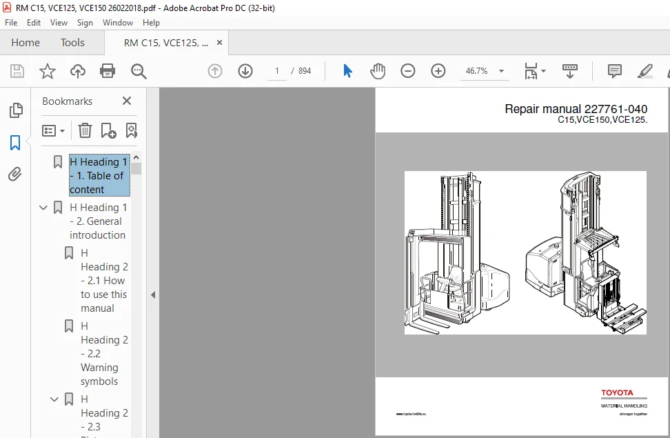
Toyota BT C15 VCE125 VCE150 Repair Manual 227761-040 – PDF DOWNLOAD
Original price was: $86.95.$30.95Current price is: $30.95.
Toyota BT C15 VCE125 VCE150 Repair Manual 227761-040 – PDF DOWNLOAD
Description
Toyota BT C15 VCE125 VCE150 Repair Manual 227761-040 – PDF DOWNLOAD
DESCRIPTION:
Toyota BT C15 VCE125 VCE150 Repair Manual 227761-040 – PDF DOWNLOAD
General introduction
How to use this manual
The repair manual is divided into chapters containing the following information:
• General safety rules
• Installation – This chapter describes the preparatory work that is to be
done before the truck is used for the first time.
• Preparation for transport – The chapter describes the work needed in
connection with preparing the truck for transport.
• Maintenance – This chapter provides an overview of periodic
maintenance.
• Service data and grease specifications – This chapter contains
information on general tightening torques and an oil and grease
specification.
• Tools – This chapter provides a list of the special tools required.
• C-coded chapters – The chapters describe the various parts/sub-systems,
e.g. the hydraulic system, what the parts look like, their function, and any
service procedures that can be made on them. These descriptions are
divided according to BT’s C code system.
Schematic drawings showing the truck electrical system and the hydraulic
system are to be found in respective C-code chapter.
• Parameters – This chapter provides a basic description of the truck
parameters.
• Calibrations – This chapter gives a basic description of how to adjust the
calibration of the truck functions that are calibrated with electrical values.
• Error codes – This chapter gives a basic description of the error codes that
may be generated by the truck sub-systems.
TABLE OF CONTENTS:
Toyota BT C15 VCE125 VCE150 Repair Manual 227761-040 – PDF DOWNLOAD
H Heading 1 – 1 Table of content 0
H Heading 1 – 2 General introduction 0
H Heading 2 – 2 1 How to use this manual 0
H Heading 2 – 2 2 Warning symbols 0
H Heading 2 – 2 3 Pictograms 0
H Heading 3 – 2 3 1 Screws/Nuts 0
H Heading 4 – Identification of tools for screws and nuts 0
H Heading 3 – 2 3 2 Repairable 0
H Heading 3 – 2 3 3 Other pictograms 0
H Heading 1 – 3 General safety rules 0
H Heading 2 – 3 1 Work safety 0
H Heading 2 – 3 2 Electrical systems 0
H Heading 2 – 3 3 Safe lifting 0
H Heading 2 – 3 4 Truck modifications 0
H Heading 1 – 4 Chassis – 0000 Truck installation 0
H Heading 2 – 4 1 General 0
H Heading 2 – 4 2 Tool list 0
H Heading 2 – 4 3 Unloading the truck 0
H Heading 3 – 4 3 1 Unloading a standing truck 0
H Heading 4 – Drive the truck off the trailer 0
H Heading 4 – Towing the truck off the trailer 0
H Heading 4 – Unloading with a counterweight truck 0
H Heading 3 – 4 3 2 Unloading a truck lying down 0
H Heading 4 – Unloading the truck from a lorry using a counter balance truck 0
H Heading 3 – 4 3 3 Unloading the truck using cranes 0
H Heading 3 – 4 3 4 Erecting the truck 0
H Heading 3 – 4 3 5 Final assembly 0
H Heading 3 – 4 3 6 Assembly of the initial mast 0
H Heading 2 – 4 4 Preparations for commissioning 0
H Heading 2 – 4 5 Installation in narrow aisle 0
H Heading 3 – 4 5 1 General 0
H Heading 3 – 4 5 2 Rail-guided truck 0
H Heading 3 – 4 5 3 Wire-guided truck 0
H Heading 3 – 4 5 4 Support arm collision guards 0
H Heading 4 – Assembling the guards during truck installation 0
H Heading 1 – 5 Truck installation 0
H Heading 2 – 5 1 General 0
H Heading 2 – 5 2 Tool list 0
H Heading 2 – 5 3 Unloading the truck 0
H Heading 3 – 5 3 1 Unloading a standing truck 0
H Heading 4 – Drive the truck off the trailer 0
H Heading 4 – Towing the truck off the trailer 0
H Heading 4 – Unloading with a counterbalance truck 0
H Heading 3 – 5 3 2 Unloading a truck lying on its back 0
H Heading 4 – Unloading the truck from a lorry using a counter balance truck from the side 0
H Heading 4 – Unloading the truck from a lorry using a counter balance truck from the rear 0
H Heading 4 – Unloading the truck using cranes 0
H Heading 3 – 5 3 3 Horizontal truck transport 0
H Heading 4 – Transport with counterbalance truck 0
H Heading 4 – Transport with crane 0
H Heading 3 – 5 3 4 Raising the truck 0
H Heading 3 – 5 3 5 Final assembly 0
H Heading 3 – 5 3 6 Installing the initial mast 0
H Heading 2 – 5 4 Preparations for commissioning 0
H Heading 2 – 5 5 Installation in narrow aisle 0
H Heading 3 – 5 5 1 General 0
H Heading 3 – 5 5 2 Rail-guided truck 0
H Heading 3 – 5 5 3 Wire-guided truck 0
H Heading 3 – 5 5 4 Support arm collision guards 0
H Heading 4 – Assembling the guards during truck installation 0
H Heading 1 – 6 Preparations for transport 0
H Heading 2 – 6 1 General 0
H Heading 2 – 6 2 Tool list 0
H Heading 2 – 6 3 Dismantling the truck 0
H Heading 2 – 6 4 Laying down the truck 0
H Heading 2 – 6 5 Loading the truck 0
H Heading 1 – 7 P2 (T code 712) – C15, VCE150 0
H Heading 2 – 7 1 Preventive maintenance – Maintenance schedule 0
H Heading 2 – 7 2 Correct inspection procedure 0
H Heading 1 – 8 P2 (t-code 713) – VCE125 0
H Heading 2 – 8 1 Preventive maintenance – Maintenance schedule 0
H Heading 2 – 8 2 Correct inspection procedure 0
H Heading 1 – 9 P3 (T code 712) – C15, VCE150 0
H Heading 2 – 9 1 Oil and lubricant specifications 0
H Heading 1 – 10 P3 (T code 713) – VCE125 0
H Heading 2 – 10 1 Oil and lubricant specification 0
H Heading 1 – 11 Tools – P4 0
H Heading 2 – 11 1 Super Seal contact 0
H Heading 3 – 11 1 1 AMP connectors 0
H Heading 3 – 11 1 2 Other tools 0
H Heading 1 – 12 Frame pivot – 0320 0
H Heading 2 – 12 1 Removal/reassembly of rear chassis, including bearings 0
H Heading 3 – 12 1 1 Special tools 0
H Heading 3 – 12 1 2 Standard hand tools 0
H Heading 3 – 12 1 3 Disassembly 0
H Heading 4 – Jack up the truck to prepare for disassembly 0
H Heading 4 – Disassembly of components 0
H Heading 3 – 12 1 4 Dismantle the rear chassis 0
H Heading 2 – 12 2 Replacing the bearing frame links 0
H Heading 3 – 12 2 1 Remove the old bearings 0
H Heading 3 – 12 2 2 Install new bearings 0
H Heading 3 – 12 2 3 Reinstall the rear chassis 0
H Heading 3 – 12 2 4 Reassemble the truck 0
H Heading 3 – 12 2 5 Lower the truck to the ground 0
H Heading 3 – 12 2 6 Final assembly 0
H Heading 1 – 13 General tightening torque – 0400 0
H Heading 2 – 13 1 Galvanised, non-oiled bolts 0
H Heading 2 – 13 2 Untreated, lubricated bolts 0
H Heading 2 – 13 3 Tightening torques 0
H Heading 1 – 14 Electric AC pump motor – 1710 1 0
H Heading 2 – 14 1 General 0
H Heading 2 – 14 2 Disassembled pump motor 0
H Heading 2 – 14 3 Disassembly and assembly of the pump motor 0
H Heading 3 – 14 3 1 Disassembly 0
H Heading 3 – 14 3 2 Installation 0
H Heading 2 – 14 4 Replacing the ball bearing 0
H Heading 3 – 14 4 1 Disassembly 0
H Heading 3 – 14 4 2 Installation 0
H Heading 2 – 14 5 Assembly instruction for the external temperature sensor 0
H Heading 1 – 15 Electric DC pump motor – 1710 2 0
H Heading 2 – 15 1 General 0
H Heading 2 – 15 2 Disassembled pump motor 0
H Heading 3 – 15 2 1 Connection 0
H Heading 2 – 15 3 Disassembly and assembly of the pump motor 0
H Heading 3 – 15 3 1 Disassembly 0
H Heading 3 – 15 3 2 Installation 0
H Heading 2 – 15 4 Replacing the ball bearing 0
H Heading 3 – 15 4 1 Disassembly (D side) 0
H Heading 3 – 15 4 2 Installation 0
H Heading 3 – 15 4 3 Disassembly (N side) 0
H Heading 3 – 15 4 4 Assembly (N side) 0
H Heading 3 – 15 4 5 Carbon brushes and carbon brush-rocker 0
H Heading 4 – New carbon brushes must always be smoothed beforehand 0
H Heading 4 – Commutator 0
H Heading 4 – Truing the commutator 0
H Heading 1 – 16 Electric drive motor – 1760 0
H Heading 2 – 16 1 General 0
H Heading 2 – 16 2 Disassembled drive motor 0
H Heading 2 – 16 3 Disassembly and assembly of the drive motor 0
H Heading 3 – 16 3 1 Disassembly of the drive motor 0
H Heading 4 – Disassemble the gear wheel 0
H Heading 4 – Disassemble the brake 0
H Heading 3 – 16 3 2 Assembly of the drive motor 0
H Heading 4 – Assemble the brake 0
H Heading 4 – Assemble the gear wheel 0
H Heading 2 – 16 4 Replacing the ball bearing 0
H Heading 3 – 16 4 1 Disassembly 0
H Heading 4 – N side 0
H Heading 4 – D side 0
H Heading 3 – 16 4 2 Installation 0
H Heading 4 – N side 0
H Heading 4 – D side 0
H Heading 2 – 16 5 Assembly instruction for the external temperature sensor 0
H Heading 1 – 17 Drive unit/gear – 2550 0
H Heading 2 – 17 1 General 0
H Heading 2 – 17 2 Components/data of the drive unit and gear 0
H Heading 3 – 17 2 1 Component identification 0
H Heading 3 – 17 2 2 Technical data 0
H Heading 3 – 17 2 3 Dismantled gear 0
H Heading 2 – 17 3 Replacing the drive motor/drive gear 0
H Heading 3 – 17 3 1 Dismantling of drive unit from truck 0
H Heading 3 – 17 3 2 Fitting the drive unit in truck 0
H Heading 3 – 17 3 3 Dismantling the drive motor and the gear 0
H Heading 3 – 17 3 4 Fitting the drive motor and the gear 0
H Heading 2 – 17 4 Oil level check/replacement 0
H Heading 3 – 17 4 1 Checking/refilling the oil 0
H Heading 3 – 17 4 2 Oil change 0
H Heading 2 – 17 5 Repairs 0
H Heading 3 – 17 5 1 Replacing the drive axle jointing ring 0
H Heading 3 – 17 5 2 Leakage from the top cover 0
H Heading 3 – 17 5 3 Leakage from the lower cover 0
H Heading 3 – 17 5 4 Replacing the wheel bolts 0
H Heading 1 – 18 Brake system – 3100 0
H Heading 2 – 18 1 General 0
H Heading 2 – 18 2 Description of functions 0
H Heading 3 – 18 2 1 Releasing the accelerator pedal 0
H Heading 3 – 18 2 2 Travel direction selector 0
H Heading 3 – 18 2 3 Pressing the brake button 0
H Heading 3 – 18 2 4 Parking brake 0
H Heading 3 – 18 2 5 Emergency braking 0
H Heading 2 – 18 3 Electro-mechanical disc brake, drive motor 0
H Heading 3 – 18 3 1 Maintenance schedule and maintenance work 0
H Heading 2 – 18 4 Replacing the brake unit and dismantling the brake unit to replace the friction disc 0
H Heading 3 – 18 4 1 Replacing the brake unit 0
H Heading 3 – 18 4 2 Dismantling a brake unit/checking/replacing a brake disc 0
H Heading 3 – 18 4 3 Check and adjust the brake force 0
H Heading 3 – 18 4 4 Clean 0
H Heading 3 – 18 4 5 Checking the air gap 0
H Heading 3 – 18 4 6 Checking and adjusting the brake force 0
H Heading 3 – 18 4 7 Troubleshooting 0
H Heading 2 – 18 5 Disc brake with multiple discs, support arms 0
H Heading 3 – 18 5 1 Checking the play/wear 0
H Heading 3 – 18 5 2 Dismantling 0
H Heading 3 – 18 5 3 Inspection 0
H Heading 3 – 18 5 4 Fitting 0
H Heading 3 – 18 5 5 Maintenance 0
H Heading 3 – 18 5 6 Adjusting the play 0
H Heading 1 – 19 Wheels – 3500 0
H Heading 2 – 19 1 Drive wheels – 3530 0
H Heading 3 – 19 1 1 General 0
H Heading 3 – 19 1 2 Disassemble the drive wheel 0
H Heading 3 – 19 1 3 Assembling the drive wheel 0
H Heading 3 – 19 1 4 Available wheel qualities 0
H Heading 2 – 19 2 Support arm wheels – 3550 0
H Heading 3 – 19 2 1 Dismantling the wheel 0
H Heading 3 – 19 2 2 Assembling the wheel 0
H Heading 3 – 19 2 3 Dismantling/assembling the wheel bearings 0
H Heading 3 – 19 2 4 Support arm wheels, shimming 0
H Heading 3 – 19 2 5 Available wheel qualities 0
H Heading 1 – 20 Steering system – 4000 0
H Heading 2 – 20 1 General 0
H Heading 3 – 20 1 1 Steering components 0
H Heading 3 – 20 1 2 Hydraulic diagram, steering system 0
H Heading 2 – 20 2 Function description 0
H Heading 3 – 20 2 1 Electrical System 0
H Heading 4 – Wire-guidance mode 0
H Heading 3 – 20 2 2 Hydraulic system 0
H Heading 3 – 20 2 3 Temperature and voltage compensation 0
H Heading 2 – 20 3 Troubleshooting 0
H Heading 3 – 20 3 1 Operations/repair, hydraulics 0
H Heading 1 – 21 Steering cylinder – 4160 0
H Heading 2 – 21 1 Instructions for checking for internal leaks 0
H Heading 3 – 21 1 1 Checks made together with 2000-hours service 0
H Heading 3 – 21 1 2 When wear is suspected 0
H Heading 2 – 21 2 Recommended procedure 0
H Heading 2 – 21 3 Remedial actions 0
H Heading 3 – 21 3 1 Measure 0
H Heading 2 – 21 4 Removing a steering cylinder from the truck 0
H Heading 2 – 21 5 Fitting a steering cylinder on the truck 0
H Heading 2 – 21 6 Repairs to the front steering cylinder mount 0
H Heading 3 – 21 6 1 Background 0
H Heading 3 – 21 6 2 Repair material 0
H Heading 3 – 21 6 3 Measures 0
H Heading 1 – 22 Wire guidance system – 4500 0
H Heading 2 – 22 1 Wire guidance 0
H Heading 3 – 22 1 1 General 0
H Heading 4 – Abbreviations 0
H Heading 4 – Definitions 0
H Heading 2 – 22 2 Wire guidance components 0
H Heading 3 – 22 2 1 Antennas, W1, W2 0
H Heading 4 – Installing a new antenna 0
H Heading 4 – Adjusting the antennas 0
H Heading 4 – Steering angle sensor, R7 0
H Heading 4 – Activation switch 0
H Heading 2 – 22 3 General description of the function 0
H Heading 4 – Narrow aisle type 0
H Heading 3 – 22 3 1 Travel speeds 0
H Heading 3 – 22 3 2 Description of the function 0
H Heading 4 – Run mode 0
H Heading 4 – Wire guidance, mode in Run mode 0
H Heading 4 – Automatic steering control 0
H Heading 2 – 22 4 “Best practice” for adjusting the wire guidance 0
H Heading 3 – 22 4 1 Set-up procedure 0
H Heading 4 – Battery check 0
H Heading 4 – Check antenna heights 0
H Heading 4 – Learn steering valves 0
H Heading 4 – Set the chassis straight and learn the pivot angle 0
H Heading 4 – Check the waist pot voltage with TruckCom 0
H Heading 4 – Learn wire guidance frequency 0
H Heading 4 – Learn the wire 0
H Heading 4 – Fine-tuning the pivot point adjustment 0
H Heading 4 – Battery setting 0
H Heading 2 – 22 5 Parameters 0
H Heading 3 – 22 5 1 General wire guidance parameters 0
H Heading 3 – 22 5 2 Learned calibration values, steering 0
H Heading 3 – 22 5 3 Learned calibration data, wire guidance 0
H Heading 2 – 22 6 Warning and error codes 0
H Heading 1 – 23 Electrical system – 5000 0
H Heading 2 – 23 1 General 0
H Heading 3 – 23 1 1 Terminologi 0
H Heading 3 – 23 1 2 Truck firmware applications 0
H Heading 3 – 23 1 3 Communication 0
H Heading 2 – 23 2 Main Computer Unit, MCU (A5) 0
H Heading 3 – 23 2 1 General 0
H Heading 3 – 23 2 2 Power supply 0
H Heading 3 – 23 2 3 Battery negative 0
H Heading 3 – 23 2 4 Electric connectors 0
H Heading 3 – 23 2 5 Internal status monitoring 0
H Heading 3 – 23 2 6 Resetting the battery indicator 0
H Heading 3 – 23 2 7 External inputs and outputs 0
H Heading 4 – X130 connector 0
H Heading 4 – I = Input, O = Output 0
H Heading 4 – X131 connector 0
H Heading 4 – X132 connector 0
H Heading 3 – 23 2 8 Installing a new card in the truck 0
H Heading 3 – 23 2 9 Programming the MCU 0
H Heading 2 – 23 3 Fork computer unit, FCU (A4) 0
H Heading 3 – 23 3 1 General 0
H Heading 3 – 23 3 2 Power supply 0
H Heading 3 – 23 3 3 Battery negative 0
H Heading 3 – 23 3 4 Electric connectors 0
H Heading 3 – 23 3 5 Safety measure 0
H Heading 3 – 23 3 6 External inputs and outputs 0
H Heading 4 – Connector plug 0
H Heading 3 – 23 3 7 Installing a new card in the truck 0
H Heading 3 – 23 3 8 Programming 0
H Heading 2 – 23 4 Integrated Control Panel, ICP (A16) 0
H Heading 3 – 23 4 1 General 0
H Heading 3 – 23 4 2 ICP modules 0
H Heading 3 – 23 4 3 Power supply 0
H Heading 3 – 23 4 4 Battery negative 0
H Heading 3 – 23 4 5 External inputs and outputs 0
H Heading 4 – X100 connector 0
H Heading 4 – X101 connector 0
H Heading 4 – X102 connector 0
H Heading 4 – X103 connector 0
H Heading 4 – X104 connector 0
H Heading 4 – X106 connector 0
H Heading 4 – X107 connector 0
H Heading 3 – 23 4 6 Installing a new ICP in the truck 0
H Heading 3 – 23 4 7 Programming 0
H Heading 3 – 23 4 8 Replacing the ICP and shock absorbers 0
H Heading 4 – Fitting the ICP 0
H Heading 4 – Remove the upper shock absorber 0
H Heading 4 – Fit the upper shock absorber 0
H Heading 4 – Remove the lower shock absorber 0
H Heading 4 – 0
H Heading 4 – Fit the lower shock absorber 0
H Heading 4 – 0
H Heading 4 – Remove the inner shock absorber 0
H Heading 4 – Fit the inner shock absorber 0
H Heading 4 – Separate the telescopic arm 0
H Heading 2 – 23 5 AC regulators, ACTL (A1), ACTR (A31) and ACH (A2) 0
H Heading 3 – 23 5 1 General 0
H Heading 3 – 23 5 2 Connection terminal and terminal pillars 0
H Heading 3 – 23 5 3 Technical data 0
H Heading 3 – 23 5 4 Installing a new frequency converter in the truck 0
H Heading 3 – 23 5 5 Programming 0
H Heading 3 – 23 5 6 Maintenance 0
H Heading 3 – 23 5 7 Safety 0
H Heading 3 – 23 5 8 Cleaning 0
H Heading 2 – 23 6 DC regulator, DCHI (A32) 0
H Heading 3 – 23 6 1 General description 0
H Heading 3 – 23 6 2 Connection terminal and terminal pillars 0
H Heading 3 – 23 6 3 Technical data 0
H Heading 3 – 23 6 4 Installing a new transistor panel 0
H Heading 2 – 23 7 Parameters 0
H Heading 2 – 23 8 Diagnostics and troubleshooting 0
H Heading 3 – 23 8 1 Maintenance 0
H Heading 3 – 23 8 2 Safety 0
H Heading 3 – 23 8 3 Cleaning 0
H Heading 3 – 23 8 4 Using the hand-held terminal 0
H Heading 3 – 23 8 5 Viewing and adjusting parameters 0
H Heading 3 – 23 8 6 SPECIAL PROGRAM MODE 0
H Heading 3 – 23 8 7 Using the TEST mode 0
H Heading 3 – 23 8 8 Using the DIAGNOSTICS MODE 0
H Heading 3 – 23 8 9 SPECIAL DIAGNOSTICS MODE 0
H Heading 2 – 23 9 Electric system, overview 0
H Heading 2 – 23 10 Symbol list and electric wiring diagram 0
H Heading 3 – 23 10 1 List of symbols 0
H Heading 3 – 23 10 2 Electrical wiring diagram VCE150A (T code 712) 0
H Heading 3 – 23 10 3 Electrical wiring diagram VCE125ASF (T code 713) 0
H Heading 2 – 23 11 Component List 0
H Heading 2 – 23 12 Component location 0
H Heading 3 – 23 12 1 Cabling contacts 0
H Heading 2 – 23 13 General description of the function 0
H Heading 2 – 23 14 Functional description, starting, driving, steering and braking 0
H Heading 3 – 23 14 1 Battery connected, truck switched off 0
H Heading 3 – 23 14 2 Log-in / Start-up 0
H Heading 3 – 23 14 3 Log-out / Switch-off 0
H Heading 3 – 23 14 4 Presence check 0
H Heading 3 – 23 14 5 Selecting the drive direction / Driving 0
H Heading 3 – 23 14 6 Emergency driving mode 0
H Heading 3 – 23 14 7 Travel speeds 0
H Heading 3 – 23 14 8 Control units 0
H Heading 3 – 23 14 9 Braking 0
H Heading 2 – 23 15 Electrical description of the hydraulic functions 0
H Heading 3 – 23 15 1 Permitted combined functions 0
H Heading 3 – 23 15 2 Monitoring and functional limitations 0
H Heading 3 – 23 15 3 Slack chain guard 0
H Heading 3 – 23 15 4 Height measurement 0
H Heading 3 – 23 15 5 Cabin lifting 0
H Heading 3 – 23 15 6 Special height (lifting height limitation) 0
H Heading 3 – 23 15 7 Cab lowering 0
H Heading 3 – 23 15 8 Special function with cab lifting/lowering and forks set straight ahead 0
H Heading 2 – 23 16 Turret head fork unit (T code 712) 0
H Heading 3 – 23 16 1 Auto rotation 0
H Heading 3 – 23 16 2 Miscellaneous electrical functions 0
H Heading 4 – Warning lamp 0
H Heading 4 – Personal protection system (PPS) 0
H Heading 3 – 23 16 3 Narrow aisle ID system 0
H Heading 3 – 23 16 4 Alternative “narrow aisle system” 0
H Heading 2 – 23 17 Shuttle fork unit (T code 713) 0
H Heading 3 – 23 17 1 Extending the forks 0
H Heading 4 – Description of the function 0
H Heading 3 – 23 17 2 Fork lifting/lowering 0
H Heading 2 – 23 18 Display 0
H Heading 3 – 23 18 1 Normal mode 0
H Heading 3 – 23 18 2 Information mode 0
H Heading 1 – 24 Parameters – 5700 0
H Heading 2 – 24 1 General 0
H Heading 2 – 24 2 Accessing parameters 0
H Heading 3 – 24 2 1 Operator parameters (service key not connected) 0
H Heading 4 – Operator parameters (operators 1-10) 0
H Heading 2 – 24 3 Truck parameters 0
H Heading 3 – 24 3 1 MCU parameters 0
H Heading 4 – Basic parameters 0
H Heading 4 – Wire guidance parameters and other new parameters 0
H Heading 4 – Learned calibration values, steering 0
H Heading 4 – Learned calibration data, wire guidance 0
H Heading 4 – Parameters Odometer function 0
H Heading 4 – Parameter Navigation Solutions 0
H Heading 4 – Parameters, Brand 0
H Heading 3 – 24 3 2 FCU parameters, turret head fork unit (T code 712) 0
H Heading 4 – Basic parameters, turret head fork unit 0
H Heading 4 – Learned calibration data, turret head fork unit 0
H Heading 3 – 24 3 3 FCU parameters, shuttle fork unit (T code 713) 0
H Heading 3 – 24 3 4 ICP parameters 0
H Heading 1 – 25 Calibration – 5700 0
H Heading 2 – 25 1 General 0
H Heading 3 – 25 1 1 Open the calibration mode 0
H Heading 3 – 25 1 2 Using the menu 0
H Heading 2 – 25 2 Calibration of the ICP controls, “CONTROLS” 0
H Heading 2 – 25 3 Calibration of steering – “STEERING” 0
H Heading 3 – 25 3 1 Calibration of the articulated centre potentiometer 0
H Heading 3 – 25 3 2 Calibration of the steering valves 0
H Heading 2 – 25 4 Calibration of wire guidance – “WIRE” 0
H Heading 3 – 25 4 1 “Learn Offset” 0
H Heading 3 – 25 4 2 Learn frequency 0
H Heading 2 – 25 5 Calibration of turret head functions, “FORKS” (T code 712) 0
H Heading 3 – 25 5 1 Counter-clockwise rotation 0
H Heading 3 – 25 5 2 Clockwise rotation 0
H Heading 3 – 25 5 3 Calibration of traversing/lifting, “TRAV/LIFT” 0
H Heading 3 – 25 5 4 Fork lowering “LOWER” 0
H Heading 2 – 25 6 Calibration for height measurement 0
H Heading 2 – 25 7 Calibration of the shuttle fork unit (T code 713) 0
H Heading 3 – 25 7 1 Calibration of traversing/lifting, “TRAV/LIFT” 0
H Heading 3 – 25 7 2 Fork lowering “LOWER” 0
H Heading 2 – 25 8 Calibration of weight indication, “WEIGHT” 0
H Heading 2 – 25 9 Calibration of the B cylinder pressure, “PRESSURE” 0
H Heading 2 – 25 10 Learning status codes – FCU 0
H Heading 1 – 26 Error codes – 5700 0
H Heading 2 – 26 1 General 0
H Heading 2 – 26 2 Warning and error codes 0
H Heading 3 – 26 2 1 Safety logic 0
H Heading 2 – 26 3 Description of warning and error codes 0
H Heading 3 – 26 3 1 ICP, code group 1 0
H Heading 4 – ICP warning codes 0
H Heading 4 – ICP error codes 0
H Heading 3 – 26 3 2 MCU, code group 2 0
H Heading 4 – MCU warning codes 0
H Heading 4 – MCU error codes 0
H Heading 3 – 26 3 3 Drive system, code group 3 0
H Heading 4 – Travel system-error codes 0
H Heading 3 – 26 3 4 Cab lift system, code group 4 0
H Heading 4 – Cab lift system-warning codes 0
H Heading 4 – Cab lift system-error codes 0
H Heading 3 – 26 3 5 Control system, code group 5 0
H Heading 4 – Control system-warning codes 0
H Heading 4 – Steering system-error codes 0
H Heading 3 – 26 3 6 Initial lift and turret head fork unit systems, code group 6 (T code 712) 0
H Heading 4 – Initial lift and turret head fork unit systems – warning codes 0
H Heading 3 – 26 3 7 Shuttle fork system – code group 6 (T code 713) 0
H Heading 4 – Initial lift and shuttle fork unit systems – warning codes 0
H Heading 3 – 26 3 8 Navigation Solutions, code group 9 0
H Heading 2 – 26 4 Extra logging functions 0
H Heading 4 – External logging unit 0
H Heading 1 – 27 Hydraulic system – 6000 0
H Heading 2 – 27 1 General 0
H Heading 2 – 27 2 Hydraulic cleanliness 0
H Heading 3 – 27 2 1 Washing 0
H Heading 3 – 27 2 2 Packaging 0
H Heading 3 – 27 2 3 Handling 0
H Heading 3 – 27 2 4 Storage 0
H Heading 3 – 27 2 5 Work procedures 0
H Heading 3 – 27 2 6 Inspection measures 0
H Heading 4 – Inspection 0
H Heading 2 – 27 3 Symbols 0
H Heading 2 – 27 4 Cabin lifting 0
H Heading 3 – 27 4 1 General 0
H Heading 3 – 27 4 2 Cabin lifting – S44 closed 0
H Heading 3 – 27 4 3 Cabin lowering – S70 closed 0
H Heading 3 – 27 4 4 AC hydraulic unit, components 0
H Heading 3 – 27 4 5 Hydraulic flow diagram, cabin lifting 0
H Heading 3 – 27 4 6 B cylinder system 0
H Heading 2 – 27 5 Fork units and steering 0
H Heading 3 – 27 5 1 General 0
H Heading 3 – 27 5 2 Hydraulic flow diagram, DC system (T code 712) 0
H Heading 3 – 27 5 3 Hydraulic diagram (T code 713) 0
H Heading 4 – Steering valve 0
H Heading 4 – Turret head fork unit valve (T code 712) 0
H Heading 4 – Shuttle fork valve blocks (T code 713) 0
H Heading 3 – 27 5 4 Fork rotation (T code 712) 0
H Heading 3 – 27 5 5 Side-shift movement 0
H Heading 3 – 27 5 6 Fork lifting 0
H Heading 3 – 27 5 7 Fork lowering 0
H Heading 3 – 27 5 8 Steering 0
H Heading 2 – 27 6 Extra hydraulic function (T code 712) 0
H Heading 3 – 27 6 1 Valves used for the extra hydraulic functions 0
H Heading 3 – 27 6 2 Hydraulic diagram, extra hydraulic function (T code 712) 0
H Heading 2 – 27 7 Operations/repair 0
H Heading 3 – 27 7 1 General 0
H Heading 4 – Work on hydraulic components 0
H Heading 3 – 27 7 2 Filter 0
H Heading 4 – Overview 0
H Heading 4 – Filter replacement (air and oil) 0
H Heading 3 – 27 7 3 Hydraulic hoses: 0
H Heading 4 – Routing 0
H Heading 3 – 27 7 4 Hydraulic connections 0
H Heading 4 – Conical hose couplings with O–ring 0
H Heading 4 – Quick change connector 0
H Heading 4 – Assembling the quick change connector 0
H Heading 4 – Dismantling the quick change connector 0
H Heading 4 – Hydraulic couplings, for valve unit 0
H Heading 4 – Pipe couplings 0
H Heading 4 – Valves 0
H Heading 3 – 27 7 5 General repair instructions, valves 0
H Heading 4 – Replacing the pressure sensor 0
H Heading 4 – Replacing the valve assembly 0
H Heading 4 – Replacing a valve section 0
H Heading 4 – Composition of valve unit 0
H Heading 4 – Replacing valve insert, routing valves 0
H Heading 4 – Installing the valve in the truck 0
H Heading 4 – Tightening torque 0
H Heading 4 – Replacing the non-return valve in the control valve 0
H Heading 1 – 28 Hydraulic tank – 6110 0
H Heading 2 – 28 1 Hydraulic tank generally 0
H Heading 2 – 28 2 Replace the hydraulic oil 0
H Heading 3 – 28 2 1 Emptying the tank 0
H Heading 4 – Preparations 0
H Heading 4 – Empty the accumulators 0
H Heading 4 – Empty the hydraulic tank, alternative 1 0
H Heading 4 – Empty the hydraulic tank, alternative 2 0
H Heading 3 – 28 2 2 Filling the hydraulic oil tank 0
H Heading 2 – 28 3 Replacing the tank 0
H Heading 2 – 28 4 Fitting the new tank 0
H Heading 1 – 29 Hydraulic pump – 6140 0
H Heading 2 – 29 1 General 0
H Heading 2 – 29 2 Bleeding the hydraulic pump 0
H Heading 3 – 29 2 1 Bleeding the hydraulic pump for steering and fork hydraulics (B) 0
H Heading 3 – 29 2 2 Bleeding the hydraulic pump for main lift (A1, A2) 0
H Heading 2 – 29 3 Replacing the hydraulic pump for main lift (A1, A2) 0
H Heading 3 – 29 3 1 Disassembly 0
H Heading 3 – 29 3 2 Installation 0
H Heading 2 – 29 4 Replacing the hydraulic pump for steering and fork hydraulics (B) 0
H Heading 3 – 29 4 1 Disassembly 0
H Heading 3 – 29 4 2 Installation 0
H Heading 2 – 29 5 Troubleshooting internal leakage in the hydraulic pump for steering and fork hydraulics (B) 0
H Heading 1 – 30 Accumulators – 6280 0
H Heading 2 – 30 1 Charging of the lifting and steering accumulators 0
H Heading 3 – 30 1 1 Preparations 0
H Heading 3 – 30 1 2 Measuring the pressure in the lifting accumulator 0
H Heading 3 – 30 1 3 Charging the lifting accumulator 0
H Heading 3 – 30 1 4 Order numbers for country-specific adapter kits 0
H Heading 2 – 30 2 Measuring the pressure in the steering accumulator 0
H Heading 3 – 30 2 1 Charging the steering accumulator 0
H Heading 1 – 31 Main lift cylinder – 6610 0
H Heading 2 – 31 1 Replacing the seal in the B cylinder 0
H Heading 1 – 32 Main mast and mast – 7100 0
H Heading 2 – 32 1 Setting the cab and mast stoppers 0
H Heading 3 – 32 1 1 Cab stoppers 0
H Heading 3 – 32 1 2 Setting the cab stoppers 0
H Heading 3 – 32 1 3 Mast stoppers 0
H Heading 1 – 33 Main lift chain system – 7120 0
H Heading 2 – 33 1 General 0
H Heading 2 – 33 2 Checking the chain setting 0
H Heading 2 – 33 3 Checking the chain 0
H Heading 3 – 33 3 1 Noise 0
H Heading 3 – 33 3 2 Surface rust 0
H Heading 3 – 33 3 3 Rusty links 0
H Heading 3 – 33 3 4 Stiff links 0
H Heading 3 – 33 3 5 Bolt rotation 0
H Heading 3 – 33 3 6 Loose bolts 0
H Heading 3 – 33 3 7 Outline wear 0
H Heading 3 – 33 3 8 Stretching 0
H Heading 3 – 33 3 9 Damage 0
H Heading 3 – 33 3 10 Damaged discs 0
H Heading 3 – 33 3 11 Damaged bolts 0
H Heading 3 – 33 3 12 Dirty chain 0
H Heading 2 – 33 4 Cleaning 0
H Heading 2 – 33 5 Lubrication 0
H Heading 2 – 33 6 Adjusting chains 0
H Heading 3 – 33 6 1 Tool list 0
H Heading 3 – 33 6 2 Main lift chain adjustment 0
H Heading 3 – 33 6 3 Cabin chain adjustment 0
H Heading 3 – 33 6 4 Initial mast chain adjustment 0
H Heading 1 – 34 Initial mast/turret head fork unit – 7200 0
H Heading 2 – 34 1 General description 0
H Heading 2 – 34 2 Adjustment 0
H Heading 2 – 34 3 Checking the chain 0
H Heading 3 – 34 3 1 Noise 0
H Heading 3 – 34 3 2 Surface rust 0
H Heading 3 – 34 3 3 Bolt rotation 0
H Heading 3 – 34 3 4 Loose bolts 0
H Heading 3 – 34 3 5 Damage 0
H Heading 3 – 34 3 6 Damaged plates 0
H Heading 3 – 34 3 7 Damaged bolts 0
H Heading 3 – 34 3 8 Dirty chain 0
H Heading 3 – 34 3 9 Initial mast installation/removal 0
H Heading 3 – 34 3 10 Mast installation 0
H Heading 3 – 34 3 11 Installation of belts on a new truck 0
H Heading 3 – 34 3 12 Installing hydraulic hoses and electric cables 0
H Heading 3 – 34 3 13 Mast removal 0
H Heading 2 – 34 4 Inspection and replacement of belts used for fork traversing 0
H Heading 3 – 34 4 1 Check 0
H Heading 3 – 34 4 2 Replacing the belt 0
H Heading 3 – 34 4 3 Checking belt tensioning 0
H Heading 2 – 34 5 Friction plate adjustment 0
H Heading 2 – 34 6 Parallel adjustment of forks 0
H Heading 3 – 34 6 1 Measuring fork parallelism 0
H Heading 1 – 35 Shuttle fork unit – 7800 0
H Heading 2 – 35 1 Installing the shuttle forks 0
H Heading 2 – 35 2 Maintenance 0
H Heading 3 – 35 2 1 Maintenance schedule 0
H Heading 3 – 35 2 2 Lubrication 0
H Heading 4 – Oil and lubricant specification 0
H Heading 3 – 35 2 3 Chain adjustment 0
H Heading 2 – 35 3 Replacing the shuttle forks 0
H Heading 2 – 35 4 Measures 0
H Heading 3 – 35 4 1 Shuttle forks coming loose from the fork carriage holders 0
H Heading 1 – 36 Magnet installation in narrow aisle – 8100 0
H Heading 2 – 36 1 General 0
H Heading 2 – 36 2 Magnetic Sensor Switch Positions 0
H Heading 2 – 36 3 Standard Magnet Positions – Rail and Wire Guided 0
H Heading 3 – 36 3 1 Number of magnet positions required per aisle 0
H Heading 2 – 36 4 Aisle indication – method of operation 0
H Heading 2 – 36 5 Aisle End Brake 0
H Heading 3 – 36 5 1 How the AEB works 0
H Heading 3 – 36 5 2 AEB Magnet Positions 0
H Heading 1 – 37 Wire guidance equipment – 8200 0
H Heading 2 – 37 1 General 0
H Heading 2 – 37 2 Generator 0
H Heading 3 – 37 2 1 Technical data 0
H Heading 1 – 38 Height preselection – 9390 0
H Heading 2 – 38 1 General 0
H Heading 2 – 38 2 Parameters 0
H Heading 3 – 38 2 1 MCU parameters 0
H Heading 2 – 38 3 Programming 0
H Heading 3 – 38 3 1 Programming a level 0
H Heading 3 – 38 3 2 Operation/Automatic operations 0
H Heading 1 – 39 Appendix A: Technical update 0
H Heading 2 – 39 1 AC pump motor, C code 1710, main lift 0
H Heading 3 – 39 1 1 Description 0
H Heading 3 – 39 1 2 Replacing the temperature sensor 0
H Heading 3 – 39 1 3 Replacing the speed sensor 0
H Heading 3 – 39 1 4 Replacing bearings 0
H Heading 2 – 39 2 AC drive motor, C code 1760 0
H Heading 3 – 39 2 1 Description 0
H Heading 3 – 39 2 2 Replacing the temperature sensor 0
H Heading 3 – 39 2 3 Replacing the speed sensor 0
H Heading 3 – 39 2 4 Disassembly 0
H Heading 3 – 39 2 5 Replacing bearings 0
H Heading 3 – 39 2 6 Assembly 0
H Heading 2 – 39 3 Motor controls, C code 5460, ACTL (A1), ACTR (A31) and ACH (A2) generation 5 0
H Heading 3 – 39 3 1 General 0
H Heading 3 – 39 3 2 ACT regulators, A1/A31 0
H Heading 4 – Technical data, ACT regulators 0
H Heading 3 – 39 3 3 ACH regulator, A2 0
H Heading 4 – Technical data, ACH regulator 0
H Heading 3 – 39 3 4 Troubleshooting 0
H Heading 4 – Troubleshooting diagram, motor control 0
H Heading 3 – 39 3 5 Power cable connections 0
H Heading 3 – 39 3 6 Installing a new frequency converter in the truck 0
H Heading 3 – 39 3 7 Programming 0
H Heading 3 – 39 3 8 Maintenance 0
H Heading 3 – 39 3 9 Safety 0
H Heading 3 – 39 3 10 Cleaning 0
H Heading 2 – 39 4 New pivot point/steering potentiometer for C15, VCE150A and VCE125ASF 0
H Heading 3 – 39 4 1 General information 0
H Heading 3 – 39 4 2 Replacing the potentiometer 0
H Heading 4 – The potentiometer’s voltage can be read via TruckCom 0
H Heading 4 – The potentiometer’s voltage cannot be read via TruckCom 0
H Heading 2 – 39 5 Wiring diagram VCE150 (T code 712) from serial number 6213314 onwards 0
H Heading 2 – 39 6 Wiring diagram VCE125ASF (T code 713) from serial number 6213314 onwards 0
H Heading 1 – 40 Index 0
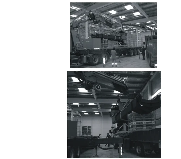
IMAGES PREVIEW OF THE MANUAL:
TOYOTA BT C15 VCE125 VCE150 REPAIR MANUAL 227761-040 – PDF DOWNLOAD:
PLEASE NOTE:
- This is the SAME MANUAL used by the dealerships to diagnose your vehicle
- No waiting for couriers / posts as this is a PDF manual and you can download it within 2 minutes time once you make the payment.
- Your payment is all safe and the delivery of the manual is INSTANT – You will be taken to the DOWNLOAD PAGE.
- So have no hesitations whatsoever and write to us about any queries you may have : heydownloadss @gmail.com
S.V