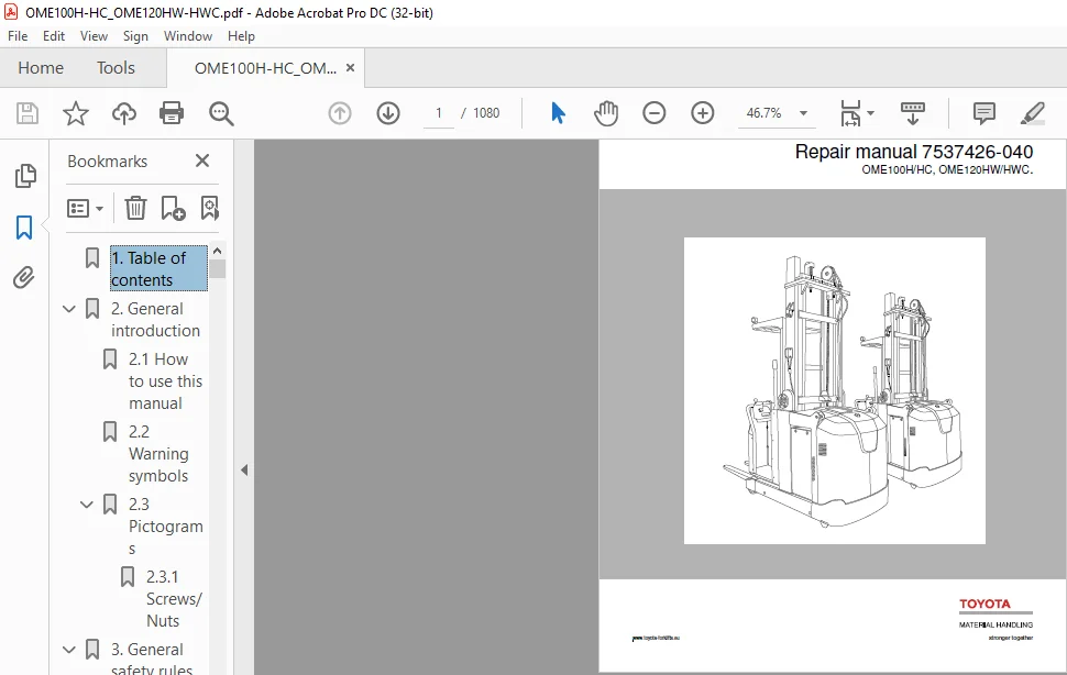
Toyota BT OME100H/HC OME120HW/HWC Repair Manual 7537426-040 – PDF DOWNLOAD
Original price was: $86.95.$30.95Current price is: $30.95.
Toyota BT OME100H/HC OME120HW/HWC Repair Manual 7537426-040 – PDF DOWNLOAD
Description
Toyota BT OME100H/HC OME120HW/HWC Repair Manual 7537426-040 – PDF DOWNLOAD
DESCRIPTION:
Toyota BT OME100H/HC OME120HW/HWC Repair Manual 7537426-040 – PDF DOWNLOAD
General introduction
How to use this manual
The repair manual is divided into chapters containing the following
information:
• Operation and connection sequences – This chapter provides a basic
description of the main functions of the truck
• Parameters – This chapter describes steering system parameters and the
calibration procedure
• Installation and commissioning – This chapter describes the work that is
necessary for commissioning of the truck
• Maintenance – This chapter includes a general diagram for regular
maintenance followed by detailed descriptions of required maintenance
procedures
• Troubleshooting – The troubleshooting chapter describes the error codes
that are displayed when the truck is partially or completely disabled. It also
describes the cause of the problem together with suggested remedies.
• Remedies – This chapter describes the various truck systems, e.g. the
hydraulic system and includes descriptions of system parts and the
necessary service procedures. These descriptions are divided according
to BT’s C code system.
• Appendices – The appendices include:
Instructions for disposal
Information about electrical components and wiring diagrams
Hydraulics diagram
List of required tools
Information about general tightening torques
Oil and grease specifications
Technical data
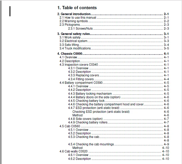
TABLE OF CONTENTS:
Toyota BT OME100H/HC OME120HW/HWC Repair Manual 7537426-040 – PDF DOWNLOAD
1 Table of contents 0
2 General introduction 0
2 1 How to use this manual 0
2 2 Warning symbols 0
2 3 Pictograms 0
2 3 1 Screws/Nuts 0
3 General safety rules 0
3 1 Work safety 0
3 2 Electrical system 0
3 3 Safe lifting 0
3 4 Truck modifications 0
4 Chassis C0000 0
4 1 Overview 0
4 2 Description 0
4 3 Inspection covers C0340 0
4 3 1 Overview 0
4 3 2 Description 0
4 3 3 Replacing covers 0
4 3 4 Fitting covers 0
4 4 Battery compartment C0390 0
4 4 1 Overview 0
4 4 2 Description 0
4 4 3 Battery locking mechanism 0
4 4 4 Battery doors on the side (option) 0
4 4 5 Checking battery lock 0
4 4 6 Checking the battery compartment hood and cover 0
4 4 7 ESD protection (anti-static braid) 0
Checking ESD protection (anti-static braid) 0
Method 0
4 4 8 Side covers (option) 0
4 4 9 Checking battery rollers 0
4 5 Cab C0560 0
4 5 1 Overview 0
4 5 2 Description 0
4 5 3 Checking the cab 0
4 5 4 Checking the cab mountings 0
Method 0
4 6 Cab walls C0520 0
4 6 1 Overview 0
4 6 2 Description 0
4 7 Side gates C0550 0
4 7 1 Overview 0
4 7 2 Description 0
Replacing the gate 0
Replacing gas damper 0
Replacing switch [S87]/[S88] 0
4 7 3 Only OME W 0
Replacing side gates 0
Replacing gas struts 0
4 8 Seat mountings C0610 0
4 8 1 Overview 0
4 8 2 Description< 0
4 9 Operator’s seat C0620 0
4 9 1 Overview 0
4 9 2 Description 0
4 9 3 Replacing the operator’s seat 0
4 10 Operator controls (mechanical) C0640 0
4 10 1 Overview 0
4 10 2 Description 0
4 10 3 Speed control 0
4 11 Wall/floor covering C0670 0
4 11 1 Overview 0
4 11 2 Description 0
4 11 3 Replacing the carpeting 0
4 12 Interior fittings C0680 0
4 12 1 Overview 0
4 12 2 Description 0
4 12 3 Removing the headlining 0
4 12 4 Fitting the headlining 0
4 13 Design plate 0
4 13 1 Overview 0
4 13 2 Description 0
4 13 3 Replacing the design plates 0
4 14 Mirrors C0740 0
4 14 1 Overview 0
4 14 2 Description 0
4 14 3 Replacing rear view mirror 0
4 14 4 Fittings 0
4 14 5 Replacing the bracket 0
4 15 Safety equipment C0800 0
4 15 1 Evacuation line 0
4 15 2 Side support lugs 0
4 16 Overhead guard/roof C0810 0
4 16 1 Overview 0
4 16 2 Description 0
4 16 3 Replacing an existing overhead guard 0
4 17 Finger guards C0820 0
4 17 1 Overview 0
4 17 2 Description 0
4 17 3 Replacing a figure guard 0
4 18 Signs, warnings, labels C0850 0
5 Motors C1000 0
5 1 Overview 0
5 2 Description 0
5 3 Pump motor C1710 0
5 3 1 Overview 0
5 3 2 Description 0
5 3 3 Removing the pump motor 0
5 3 4 Fitting the pump motor 0
5 3 5 Replacing the temperature sensor 0
5 3 6 Replacing the speed sensor 0
5 3 7 Cleaning 0
5 3 8 Replacing the oil pump 0
5 3 9 Replacing the bearings 0
5 4 Steering servo motor C1730 0
5 4 1 Overview 0
5 4 2 Description 0
5 4 3 Replacing the steering servo motor 0
5 4 4 Layout of the flange holes 0
5 5 Fan motors C1740 0
5 5 1 Overview 0
5 5 2 Description 0
5 5 3 Replacing the frequency converter fan 0
5 5 4 Replacing the motor compartment fan 0
5 6 Drive motor, C1760 0
5 6 1 Overview 0
5 6 2 Description 0
5 6 3 Removing the drive motor 0
5 6 4 Fitting the drive motor 0
5 6 5 Replacing the temperature sensor 0
5 6 6 Replacing the rotational speed sensor 0
5 6 7 Disassembling the drive motor 0
5 6 8 Cleaning 0
5 6 9 Replacing the bearings 0
5 6 10 Assembling the drive motor 0
6 Transmission/drive gear C2000 0
6 1 Overview 0
6 2 Drive gear C2550 0
6 2 1 Overview 0
6 2 2 Description 0
6 2 3 Inspection measures 0
Inspection <TBD> 0
6 2 4 Changing oil 0
6 2 5 Leakage from the lower cover 0
6 2 6 Checking the oil level 0
6 2 7 Removing the drive gear 0
6 2 8 Fitting the drive gear 0
7 Brake system/Wheels C3000 0
7 1 Overview 0
7 2 Brake system C3100 0
7 2 1 Overview 0
7 2 2 Description 0
Travel brake 0
Parking brake 0
Emergency brake 0
7 2 3 Support arm brake (option) C3180 0
7 2 4 Overview 0
7 2 5 Description 0
7 2 6 Inspection measures (support arm brake, wiring harness and connectors) 0
Inspection 0
Wear 0
7 2 7 Support arm brake replacement 0
7 2 8 Checking the brake unit’s clearance 0
7 2 9 Checking disc thickness 0
7 2 10 Fitting the brake unit 0
7 2 11 Checking braking distance 0
7 3 Parking brake C3300 0
7 3 1 Overview 0
7 3 2 Description 0
7 4 Parking brake C3370 0
7 4 1 Overview 0
7 4 2 Checking the parking brake clearance 0
7 4 3 Checking braking force 0
7 4 4 Replacing the brake unit 0
7 4 5 Disassembly and wear inspection 0
7 4 6 Adjusting the clearance 0
7 5 Emergency brake release 0
7 5 1 Releasing the brake in case of a faulty parking brake unit 0
7 5 2 Releasing the brake when the parking brake unit is intact 0
7 5 3 0
7 6 Wheels C3500 0
7 7 Wheel track C3510 0
7 8 Drive wheel C3530 0
7 8 1 Overview 0
7 8 2 Inspection procedures 0
Inspection 0
Surface cracks 0
Wear 0
7 8 3 Replacing the drive wheel 0
7 8 4 Wheel stud replacement 0
7 9 Support arm wheel C3550 0
7 9 1 Overview 0
7 9 2 Inspection procedures 0
7 9 3 Removing the support arm wheel 0
7 9 4 Mounting the support arm wheel 0
7 9 5 Bearing replacement 0
7 10 0
7 11 Side guide wheel C3580 (option) 0
7 11 1 Overview 0
7 11 2 Description 0
7 11 3 Replacing the side guide wheels (High profile) 0
Dismantling 0
Fitting 0
7 11 4 Adjusting the side guide wheels (High profile) 0
7 11 5 Replacing the side guide wheels (Low profile) 0
Dismantling 0
Assembly 0
7 11 6 Adjusting the side guide wheels (Low profile) 0
8 Steering system C4000 0
8 1 Electric steering system C4300 0
8 1 1 Description 0
8 2 Electric steering wheel C4310 0
8 2 1 Description 0
8 2 2 Overview 0
8 2 3 Replacing the steering wheel 0
8 2 4 Replacing the steering wheel knob 0
8 2 5 Replacing the pulse transducer 0
8 2 6 Steering unit C4330 0
8 2 7 Steering harness C4340 0
Overview 0
8 3 Steering unit C4330 0
8 3 1 Description 0
8 4 Steering harness C4340 0
8 5 Steering angle reference sensor C4350 0
8 5 1 Description 0
8 5 2 Overview 0
8 5 3 Replacing the steering angle reference sensor 0
8 5 4 0
8 5 5 Replacing the steering bearing 0
8 5 6 0
8 6 Steering bearing C4380 0
8 6 1 Description 0
8 6 2 Overview 0
8 6 3 Replacing the steering bearing 0
8 6 4 0
8 7 Wire guidance C4510 0
8 7 1 Description 0
Wire guidance signal/Antenna coils 0
8 7 2 Operating modes 0
8 7 3 Overview 0
8 8 Wire guidance, antennas C4540 0
8 9 Wiring harness for wire/rail guidance C4550 0
8 9 1 Overview 0
8 9 2 0
8 10 Rail guidance C4510 0
8 10 1 Description 0
8 10 2 Operating modes 0
8 11 Wire guidance, antenna C4540 0
8 12 Wire guidance, wiring harness C4550 0
9 Electrical system C5000 0
9 1 Cabling C5100 0
9 1 1 Chassis wiring 0
Overview 0
Connections 0
Replacing chassis harness 0
9 1 2 High voltage supply to fuse panel 0
Overview 0
Connections 0
9 1 3 Mast harness – Sensor 0
Overview 0
Connections 0
9 1 4 Mast harness – Power supply/Functions 0
Overview 0
Connections 0
Replacing the mast harness 0
9 1 5 Cab harness – Floor 0
Overview 0
Connections 0
9 1 6 Cab harness – Roof 0
Overview 0
Connections 0
9 1 7 Cab harness – Operating panel 0
Overview 0
Connections 0
9 1 8 Cab harness – Side gates 0
Overview 0
Connections 0
9 1 9 Cab harness – Initial lift [B89] 0
Overview 0
Connections 0
Replacing the cab harness 0
Reposition the carpet in the cab 0
9 1 10 Internal wiring harness, right hand operating panel 0
Overview 0
Connections 0
9 1 11 Internal wiring harness, left hand operating panel 0
Overview 0
Connections 0
9 1 12 Wiring harness for support arm brakes 0
Overview 0
Connections 0
9 1 13 VNA – Wiring harness for wire guidance antennas 0
Other 0
Connections 0
9 1 14 VNA – Wiring harness for aisle sensor in fork end 0
Overview 0
Connections 0
9 1 15 VNA – Wiring harness for aisle sensor at drive wheel end 0
Overview 0
Connections 0
9 2 Battery C5110 0
9 2 1 Battery recommendation 0
Chassis width 1050 mm 0
Chassis width 1250 mm 0
9 2 2 Measuring discharge current 0
9 2 3 Voltage measurement 0
9 2 4 Inspection measures 0
Inspection 0
9 2 5 Replacing the battery 0
9 3 Lighting C5120 0
9 3 1 Overview 0
9 3 2 Replacing fittings 0
9 4 Sound and light signals C5160 0
9 4 1 Horn [P4] 0
9 4 2 Warning light [P5] 0
9 4 3 Overview 0
9 4 4 Replacing the alarm unit 0
9 5 Main contactor C5190 0
9 5 1 Overview 0
9 5 2 Replacing the main contactor 0
9 6 Central Information Display – CID C5200 0
9 6 1 Overview 0
9 6 2 Technical data 0
9 6 3 Connections 0
9 6 4 Indications and keypad 0
LED symbols 0
Screen 0
Keypad 0
Navigation 0
Configuration functions 0
Service functions 0
Calibration functions 0
9 6 5 Replacing the CID 0
9 7 Height indicator/preselector (Option) 0
9 7 1 Symbols 0
9 7 2 Travel warning 0
9 7 3 Height preselector levels 0
9 7 4 Level selection 0
9 7 5 Using the height preselector 0
Aisle and level selection 0
Presets 0
9 7 6 Program the level 0
9 7 7 Deleting a level 0
9 7 8 Height preselector and TruckCom 0
9 7 9 Lift/lowering movement 0
Parameter settings, lift/lowering movement 0
9 7 10 Parameter overview, height preselector 0
9 8 Speed control C5330 0
9 8 1 Overview 0
9 8 2 Inspection measures 0
Inspection 0
9 8 3 Replacing travel speed sensor [B34] 0
9 8 4 Replacing brake sensor [B32] 0
9 9 Output control 0
9 9 1 Common for drive motor and pump motor 0
9 9 2 Drive motor – ACT C5460 0
9 9 3 Overview 0
9 9 4 Replacing the ACT 0
9 10 Pump motor – ACH C5660 0
9 11 Function control C5510 0
9 11 1 Left operating panel 0
9 11 2 Right operating panel 0
9 11 3 Control location 0
9 11 4 Simplified twin control 0
9 11 5 Overview 0
9 11 6 Control in fork direction 0
Replacing sensor [B28], cab lift up 0
Replacing sensor [B29], cab lift down 0
Replacing sensor [B35], horn 0
Replacing sensor [B55], initial lift up 0
Replacing sensor [B56], initial lift down 0
9 11 7 Control in drive wheel direction 0
Replacing sensor [B28], cab lift up 0
Replacing sensor [B29], cab lift down 0
Replacing sensor [B35], horn 0
Replacing sensor [B55], initial lift up 0
Replacing sensor [B56], initial lift down 0
9 11 8 Simplified twin control 0
Replacing switch S101 0
Replacing switch S108 0
Replacing switch S109 0
9 11 9 0
9 12 Main processor – MCU C5710 0
9 12 1 Replacing the MCU 0
9 13 Fuse panels C5790 0
9 13 1 Fuse panel [A9] 0
Fuses 0
[K20] Key relay 0
[S133] Emergency brake release 0
9 13 2 Fuse panel Cab 0
9 13 3 t 0
9 13 4 Overview 0
9 13 5 Replacing the complete fuse panel [A9] 0
9 13 6 Replacing the complete fuse panel Cab 0
9 13 7 Replacing the mast harness 0
9 14 Sending units and sensors C5800 0
9 14 1 Inductive sensors 0
9 14 2 Position sensor 0
Steering reference sensor 0
9 14 3 Capacitive sensors 0
9 14 4 Pressure sensor 0
9 14 5 Replacing pressure sensor [B4] for fork load 0
9 14 6 Pulse transducers 0
Steering sensor 0
9 15 Position sensor, lift/lowering C5820 0
9 15 1 Cab lift [B25] 0
Location 0
Task and function 0
Connections and voltage supply 0
9 15 2 Initial lift [B89] 0
Location 0
Task and function 0
Connections and voltage supply 0
9 15 3 Overview 0
9 15 4 Replacing sensor [B89] for initial lift in top position 0
9 15 5 0
9 15 6 Load on forks [B91] 0
Location 0
Task and function 0
9 15 7 Replacing sensor [B91] for load on forks (OME W) 0
9 16 Safety sensor C5830 0
9 16 1 [B51]/[B52] Safety handle 0
9 16 2 Replacing the right hand safety handle [B51] 0
9 16 3 Replacing the left hand safety handle [B52] 0
9 16 4 Replacing emergency switch off [S21] 0
9 16 5 Replacing emergency switch off [S22] 0
9 16 6 [S87]/[S88] Side gates 0
Replacing the gate switch 0
Side gates [S87]/[S88], all models 0
9 16 7 [B92] Operator in cab 0
Location 0
Task and function 0
Connections and voltage supply 0
9 16 8 Slack chain switches 0
[S81]/[S82] Slack chain switches, cab lift (Triplex mast only) 0
[S83]/[S84] Slack chain switches, cab 0
9 16 9 Replacing switch for slack chain guard [S83]/[S84], lower 0
9 16 10 Replacing switch for slack chain switch [S81]/[S82], upper 0
9 17 Narrow aisle sensor C5840 0
9 17 1 Magnet sensor 0
9 17 2 Photocell 0
9 17 3 Narrow aisle detection 0
[B110] and [B111] – Magnet sensor 0
Voltage feed 0
Magnet detection 0
9 17 4 [B110] – [B115] Aisle sensors 0
Retrofitting of [B110] to [B113] 0
Replacing aisle sensor [B110] 0
Replacing aisle sensor [B111] 0
[B114] and [B115] – Photocells 0
9 17 5 [B112]/[B113] End of aisle retardation 0
Voltage feed 0
Magnet detection 0
Replacing sensor [B112] for end of aisle retardation 0
Replacing sensor [B113] for end of aisle retardation 0
Replacing photocell [B114] 0
Replacing photocell [115] 0
9 17 6 [B116] and [B117] End of aisle stop 0
Photocell 0
Voltage feed 0
Wiring harness – Overview 0
Wiring harness – Connections 0
Replacing sensor [B116] 0
Replacing sensor [B117] 0
Status – MCU inputs 0
9 17 7 [B172] – [B174] Aisle ID 0
Photocell 0
Voltage feed 0
Wiring harness – Overview 0
Wiring harness – Connections 0
Status – MCU inputs 0
Replacing sensor [B172] 0
Replacing sensor [B173] 0
Replacing sensor [B174] 0
9 18 Positioning sensor C5850 0
10 § Hydraulic system C6000 0
10 1 Hydraulic cleanliness 0
10 1 1 Cleaning 0
10 1 2 Packaging 0
10 1 3 Handling 0
10 1 4 Storage 0
10 1 5 Work procedures 0
10 1 6 Inspection procedures 0
Inspection 0
10 2 Hydraulic unit C6100 0
10 2 1 Overview 0
10 2 2 Tank C6110 0
10 2 3 Emptying the tank 0
10 2 4 Filling the tank 0
10 2 5 Replacing the tank 0
10 2 6 Replacing the hydraulic pump 0
10 2 7 Bleeding the hydraulic system 0
10 3 Filter C6130 0
10 3 1 Filter replacement (for air and oil) 0
Method 0
10 3 2 Hydraulic pump C6140 0
10 4 Main valve C6210 0
10 4 1 Overview 0
10 4 2 Replacing the main valve assembly 0
Method 0
10 4 3 Replacing the tank proportional valve coil 0
10 4 4 Replacing the valve 0
Valve calibration 0
10 4 5 Replacing the pressure sensor 0
10 4 6 Emergency lowering 0
10 4 7 Inserts for quick change connector 0
10 4 8 Initial lifting 0
Lift 0
Pressure limitation 0
Lowering 0
10 4 9 Cage lifting 0
Lift – Models with initial lift 0
Lift – W models 0
Pressure limitation – Models with initial lift 0
Pressure limitation – W models 0
Lowering – Models with initial lift 0
Lowering – W models 0
10 4 10 Emergency lowering 0
10 4 11 Filtering the hydraulic oil 0
10 5 Hydraulic hoses C6230 0
10 5 1 Overview 0
10 5 2 Service measures 0
10 5 3 Conical connection with O–ring 0
Replacing the connection 0
Tightening torque 0
10 5 4 Seal 0
Replacing the seal 0
Tightening torque 0
10 5 5 Pipe coupling 0
Replacing the coupling 0
Tightening torque 0
10 5 6 Quick change connector 0
Overview 0
Assembling the quick change connector 0
Disassembling the quick change connector 0
10 5 7 Replacing chassis-mounted hydraulic hoses C6230 0
Hydraulic hose, valve unit-pump 0
Hydraulic hose, return oil 0
Hydraulic hose, initial lift 0
Hydraulic hose, cab lift cylinder 0
Replacing hydraulic hoses afterhose rupture, initial lift and cab lift cylinders 0
10 5 8 Replacing mast-mounted hydraulic hoses C6320 0
Hydraulic hose, mast 0
Hydraulic hose, cable chain 0
Hydraulic hose, cab 0
Hydraulic hose, under cab floor 0
10 6 Hydraulic cylinders C6600 0
10 6 1 Cab lift C6610 0
Replacing the cab lift cylinder, Dx mast 0
10 6 2 Initial lift C6620 0
Replacing the initial lift cylinder 0
Reconditioning the initial lift cylinder 0
Replacing the cab lift cylinder, Tx mast 0
Reconditioning the cab lift cylinder 0
11 Mast C7000 0
11 1 Available combinations 0
11 1 1 OME100H/Duplex 0
11 1 2 OME100H/Triplex 0
11 1 3 OME120HW/Duplex 0
11 1 4 OME120HW/Triplex 0
11 2 Cab lift C7100 0
11 2 1 Overview 0
11 2 2 Inspection measures 0
11 2 3 Replacing the bearings 0
11 2 4 Adjusting and shimming 0
11 3 Cab lift chain system C7120 0
11 3 1 <TBD>Overview 0
11 3 2 Check 0
11 3 3 Lubrication 0
11 3 4 Adjustment 0
11 3 5 Replacing the mast chain 0
Overview 0
For both the Dx and the Tx masts 0
11 4 Damper C7150 0
11 4 1 Replacing the upper damper element 0
11 4 2 Replacing the rattle plate 0
11 5 Initial lift C7160 0
11 5 1 Overview 0
11 5 2 Fork carriage 0
Removing a fork carriage with adjustable forks 0
Removing a fork carriage with fixed forks 0
Attaching a fork carriage with adjustable forks, excluding adjusting and shimming 0
Attaching a fork carriage with fixed forks, excluding adjusting and shimming 0
Removing the initial lift cylinder 0
Fitting the initial lift cylinder 0
Replacing the bearings 0
Adjusting and shimming 0
11 5 3 Chain system 0
Checking 0
Lubrication 0
Chain replacement – initial lift 0
Removing the chain roller – initial lift 0
Fitting the chain roller – initial lift 0
Removing the chain roller yoke – initial lift 0
Fitting the chain roller yoke – initial lift 0
Chain bolt replacement – initial lift 0
Adjusting the chain and fork height 0
11 6 Main mast mountings C7190 0
11 6 1 Inspection measures 0
11 7 Forks C7410 0
11 7 1 Overview 0
11 7 2 Inspection procedures 0
Inspection 0
Inspection intervals 0
Surface cracks 0
Difference in height between the fork tips 0
Position lock 0
Marking legibility 0
Wear – fork blade and fork face 0
Wear – fork mounting fixtures 0
11 7 3 Repairs and testing 0
Repairs 0
Testing the yield point 0
11 7 4 Replacement 0
12 Peripherals C8000 0
12 1 Magnet layout 0
12 1 1 Overview 0
12 1 2 Function 0
Rail guidance 0
Wire guidance 0
12 1 3 Alternative layout 0
12 2 Photocell layout 0
12 2 1 “In narrow aisle” 0
12 2 2 Aisle ID 0
12 2 3 End of aisle stop 0
13 Options/Extra equipment C9000 0
13 1 Radio equipment C9330 0
13 2 Extra lighting C9360 0
13 2 1 Toyota Wireless Information System (T W I S ) 0
13 2 2 SmartCard 0
13 3 Other extra equipment C9500 0
13 3 1 Horizontal E-bar 0
13 3 2 Fire extinguisher 0
13 3 3 Impact sensor 0
Replace 0
Setting all 0
Resetting 0
Readout 0
13 3 4 Storage basket C9500 0
14 Operation and connection sequences 0
14 1 Battery is connected 0
14 2 Logging in 0
14 3 Basic control criteria 0
14 4 Driving outside narrow aisle 0
14 5 Driving in narrow aisle 0
14 6 Braking in neutral 0
14 7 Reverse braking 0
14 8 Brake operation via controls 0
14 9 Steering 0
14 9 1 Manual steering 0
14 9 2 Wire guidance 0
14 9 3 Rail guidance 0
14 10 Initial lift up 0
14 11 Initial lift down 0
14 12 Cab lift up 0
14 13 Cab lift down 0
14 14 Logout 0
14 15 Emergency lowering 0
15 Parameters 0
15 1 Definition of cab height 0
15 2 Display/change parameters 0
15 3 Operator parameters 0
15 3 1 Overview 0
15 3 2 Connection to logged-in operator 0
15 3 3 Parameter 1 – Steering 0
15 3 4 Parameters 2, 3 6 and 7 – Maximum travel speed 0
15 3 5 Parameters 4 and 5 – Acceleration/Deceleration 0
15 4 General service parameters 0
15 4 1 Overview 0
15 4 2 Description 0
Parameter 101/104 – Service/Log-out 0
Parameters 105/106/113/114/115/117 – Alarm 0
Parameters 107/108 – Battery 0
Parameters 109/110/111/112 – Impact sensor 0
15 5 Service parameters, travel functions 0
15 5 1 Overview 0
15 5 2 Description 0
Parameter 201 – Deceleration when reversing 0
Parameters 202/203/204 – Adjusting erroneous, maximum travel speeds 0
Parameters 205/206/207 – Adjusting erroneous, maximum travel speeds 0
Parameter 209/210 – Maximum travel speed above a certain cab height 0
Parameters 211/212/213/214/215/216 – Adjusting erroneous, maximum travel speeds 0
15 6 Service parameters, hydraulics 0
15 6 1 Overview 0
15 6 2 Description 0
Parameter 333 – Transport mode 0
Parameters 341/342/343/344 – Adjusting application dependent, maximum cab and initial lift movements 0
Parameter 345/346 – Cab height when platform gates are locked 0
Parameter 347 – Platform height when side gates are locked 0
Parameter 348 – Maximum cab height with front gates open or without a load on the forks 0
Parameter 349 – Cab height when locking cab front gate 0
Parameter 350 – Activation of cab speed reduction 3 seconds 0
Parameter 351/352 – Lift height limitations outside of narrow aisle 0
Parameter 353/354 – Configuration of lift height limitations outside of narrow aisle 0
Parameter 356/357 – Allow opening gate in narrow aisle 0
Parameter 358 – Configuring the pallet sensor 0
Parameter 359 – Configuration of buzzer when cab side gate is open 0
Parameter 367 – Height for lowering limit 0
Parameter 368 – Configuring the lowering limit 0
Parameters 371 through 379 – Height preselector 0
Parameter 380 through 386 – Lift height limitations in narrow aisle 0
Parameters 387 through 394 – Configuration of lift height limitations in narrow aisle 0
Parameters 395 through 399 – Function-dependent maximum cab heights 0
Parameter 607 is used to specify how the truck will slow down when it leaves the centre of the aisle 0
15 7 Service parameters, CID 0
15 7 1 Overview 0
15 7 2 Description 0
Parameter 503 – Login method 0
Parameters 504/505/506/507 – Smart Access 0
Parameters 508, 509, 512, 513 and 515 – CID configuration 0
Parameters 510/511 – Height pre-selection 0
15 8 Service parameters, VNA 0
15 8 1 Overview 0
15 8 2 Description 0
Parameters 601/602/603/604/605 – Truck over wire 0
Parameter 606 – Wire guidance frequency 0
Parameters 607/608/609/610 – Speed reduction and stop at aisle ends 0
Parameter 611/612/613/614 – Optipace in narrow aisle 0
15 9 General factory parameters 0
15 9 1 Overview 0
15 9 2 Description 0
Parameters 1001/1002/1004/1005/1006/1008/1009 – General factory parameters with several choices 0
15 10 Factory parameters, narrow aisle 0
15 10 1 Overview 0
15 10 2 Description 0
Parameter 1020 – Distance between wire guidance antennas 0
Parameter 1021 – Aisle indication, wire guidance 0
Parameter 1022 – Aisle indication, rail guidance 0
Parameter 1023 – Activation of aisle-end brake (AEB) 0
Aisle end brake must be activated with parameter “1113” in order for parameter “1023” to be used 0
Parameter 1024 – Aisle layout 0
Parameter 1025 – Sensor direction 0
15 11 Factory parameters, activation of options 0
15 11 1 Overview 0
15 11 2 Description 0
15 12 Parameter 1119 – Lockable side gates, cab 0
15 12 1 Description of the function 0
The cab is below the height of the reference sensor [B25], and the height is not determined 0
The cab is lower than P347 0
The truck is in a narrow aisle, and P356 = “1” 0
Parameter 356 = “0”, and the cab is above P347 0
The cab is higher than P355 0
15 13 Parameter 1120 – Lockable side gates, platform 0
The cab is below the height of the reference sensor [B25], and the height is not determined 0
The gate lock is opened by activating GFU output X133:37 “Side lock control” – changes status from 0 V to +48 V 0
The cab is lower than P345 0
The truck is in a narrow aisle, and P357 = “1” 0
The cab is higher than P355 0
15 14 Parameter 1121 – Lockable front gates, platform 0
The cab is below the height of the reference sensor [B25], and the height is not determined 0
The gate lock is opened by activating GFU output X133:10 “Front lock control” – changes status from 0 V to +48 V 0
The cab is lower than P346 0
The cab is higher than P346 0
The cab is higher than P355 0
15 15 Parameter 1122 – Lockable front gates, cab 0
The cab is below the height of the reference sensor [B25], and the height is not determined 0
The gate lock is opened by activating GFU output X133:24 “Cab front lock control” – changes status from 0 V to +48 V 0
The cab is lower than P349 0
The cab is higher than P349 0
The cab is higher than P355 0
15 16 Factory parameters, calibration 0
Hydraulic system 0
Wire guidance (with parameter 606 = 2) 0
Controls 0
16 Installation 0
16 1 Transporting the truck 0
16 2 Taking into operation 0
16 2 1 For both rail and wire guidance 0
16 2 2 Rail guidance 0
16 2 3 Wire guidance 0
16 2 4 Parameter setting 0
Setting battery parameters 0
Setting maximum travel speed 0
16 2 5 Configuration 0
Calendar 0
PIN-code handling 0
16 2 6 Test driving and checks 0
Functions 0
In narrow aisle 0
Options: T W I S and Impact sensor 0
17 Maintenance 0
17 1 Introduction 0
17 2 Safety precautions for maintenance work 0
17 3 Maintenance instructions 0
17 3 1 Cleaning and washing 0
17 3 2 High-pressure washing 0
17 3 3 Degreasing agents 0
17 3 4 Cleaning the exterior 0
17 3 5 Cleaning the chain 0
17 3 6 Cleaning the motor compartment 0
17 3 7 Electric components 0
17 4 Symbols 0
17 5 Safety checks 0
17 6 First service – 250 h 0
17 7 Periodic maintenance 0
17 7 1 Every 500 operating hours/180 days 0
Function check 0
Preventive maintenance 0
17 7 2 Every 1000 operating hours/360 days 0
17 7 3 Every 2000 operating hours/720 days 0
Function check 0
17 7 4 Every 3000 operating hours/1080 days 0
Preventive maintenance 0
17 7 5 Every 5000 operating hours/1800 days 0
Preventive maintenance 0
18 Troubleshooting 0
18 1 Auxiliary functions 0
18 1 1 Error log menu 0
Description 0
Access 0
18 1 2 Error information menu 0
Description 0
Access 0
18 1 3 Diagnostic screens 0
Description 0
Access 0
Screen 1 – CID analogue inputs 0
Screen 2 – CID digital inputs 0
Screen 3 – MCU analogue inputs 0
Screen 4 – MCU digital inputs 0
Screen 5 – MCU digital outputs 0
Screen 6 – Pulse-width modulated outputs 0
Screen 9 – GFU digital inputs/outputs 0
Screen 11 – Temperatures 0
Screen 12 – Voltages 0
Screen 13 – Travel function 0
Screen 14 – Steering function 0
Screen 15 – Hydraulic functions 1 0
Screen 16 – Hydraulic functions 2 0
Screen 18 – VNA functions 0
Screen 19 – Pressure sensor 0
18 2 Initial troubleshooting 0
18 3 Troubleshooting using blocking symbol 0
18 4 Troubleshooting using error codes 0
18 4 1 CID – Group 1 0
18 4 2 MCU – Group 2 0
18 4 3 Drive system – Group 3 0
18 4 4 Hydraulic system – Group 4 0
18 4 5 Steering system – Group 5 0
18 4 6 Narrow aisle equipment – Group 6 0
18 4 7 GFU – Group 8 0
18 5 Troubleshooting without an error code 0
18 5 1 Abnormal indications 0
18 5 2 Abnormal noise during certain manoeuvres 0
18 5 3 Abnormal or missing function 0
19 Chassis C0000 0
19 1 Frame/Chassis C0300 0
19 1 1 Inspection procedures 0
19 2 Floor C0330 0
19 3 Hoods and covers C0340 0
Removing hatches and covers 0
Securing the hoods and covers 0
19 4 Battery compartment parts C0390 0
19 4 1 Checking battery lock 0
19 4 2 Checking the battery compartment hood and cover 0
19 4 3 Side covers (option) 0
19 4 4 Checking battery rollers 0
19 5 Frame/chassis components C0400 0
19 5 1 ESD protection (anti-static braid) 0
Checking ESD protection (anti-static braid) 0
Method 0
19 6 Cab anchorage C0510 0
19 7 Cab walls C0520 0
19 8 Side gates C0550 0
19 8 1 All models 0
Replacing the gate 0
Replacing gas damper 0
Replacing switch [S87]/[S88] 0
19 8 2 Only OME W 0
Replacing the gate 0
Replacing gas damper 0
19 9 Cab C0560 0
19 9 1 Overview 0
19 9 2 Inspection procedures 0
Inspection 0
19 9 3 Checking the cab mountings 0
19 10 Seat fixing pointsC0610 0
19 11 Operator’s seat C0620 0
19 12 Operator controls C0640 0
19 13 Wall/floor covering C0670 0
19 13 1 Overview 0
19 13 2 Replacing the carpeting 0
19 14 Interior fittings C0680 0
19 14 1 Roof lining 0
Removal 0
Installing 0
19 14 2 Replacing design plates 0
19 15 Mirrors C0740 0
19 15 1 Replacing rear view mirror 0
19 15 2 Replacing the bracket 0
19 16 Safety equipment C0800 0
19 16 1 Emergency escape wire 0
19 16 2 Side support lugs 0
19 17 Overhead guard C0810 0
19 18 Finger guards C0820 0
19 19 Signs, warnings and adhesive labels C0850 0
20 Motors C1000 0
20 1 Pump motor C1710 0
20 1 1 Overview 0
20 1 2 Removing the pump motor 0
20 1 3 Installing the pump motor 0
20 1 4 Replacing the temperature sensor 0
20 1 5 Replacing the rpm-sensor 0
20 1 6 Cleaning 0
20 1 7 Replacing the oil pump 0
20 1 8 Replacing bearings 0
20 2 Steering servo motor C1730 0
20 2 1 Overview 0
20 2 2 Replacing the steering servo motor 0
20 3 Fan motor C1740 0
20 3 1 Overview 0
20 3 2 Replacing the frequency converter fan 0
20 3 3 Replacing the motor compartment fan 0
20 4 Drive motor, C1760 0
20 4 1 Overview 0
20 4 2 Removing the drive motor 0
20 4 3 Installing the drive motor 0
20 4 4 Replacing the temperature sensor 0
20 4 5 Replacing the rpm-sensor 0
20 4 6 Disassembly 0
20 4 7 Cleaning 0
20 4 8 Replacing bearings 0
20 4 9 Assembly 0
21 Drive gear C2000 0
21 1 Drive gear C2550 0
21 1 1 Overview 0
21 1 2 Inspection measures 0
Inspection <TBD> 0
21 1 3 Oil change 0
21 1 4 Leakage from the lower cover 0
21 1 5 Checking the oil level 0
21 1 6 Removing the drive gear 0
21 1 7 Fitting the drive gear 0
22 Brake/wheel systems C3000 0
22 1 Support arm brake C3180 0
22 1 1 Overview 0
22 1 2 Inspection measures (support arm brake, wiring harness and connectors) 0
Inspection 0
Wear 0
22 1 3 Support arm brake replacement 0
22 1 4 Checking the brake unit’s clearance 0
22 1 5 Checking disc thickness 0
22 1 6 Assembling the brake unit 0
22 1 7 Checking braking distance 0
22 2 Parking brake C3370 0
22 2 1 Overview 0
22 2 2 Checking the parking brake clearance 0
22 2 3 Checking braking force 0
22 2 4 Replacing the brake unit 0
22 2 5 Disassembly and wear inspection 0
22 2 6 Adjusting the clearance 0
22 3 Emergency brake release 0
22 3 1 Releasing the brake in case of a faulty parking brake unit 0
22 3 2 Releasing the brake when the parking brake unit is intact 0
22 4 Drive wheel C3530 0
22 4 1 Overview 0
22 4 2 Inspection procedures 0
Inspection 0
Surface cracks 0
Wear 0
22 4 3 Replacing the drive wheel 0
22 4 4 Wheel stud replacement 0
22 5 Support arm wheel C3550 0
22 5 1 Overview 0
22 5 2 Inspection procedures 0
22 5 3 Removing the support arm wheel 0
22 5 4 Mounting the support arm wheel 0
22 5 5 Bearing replacement 0
22 6 Side guide wheel C3580 (option) 0
22 6 1 Overview 0
22 6 2 Replacing the bracket for guide wheels 0
22 6 3 Replacing guide wheels (high profile) 0
22 6 4 Replacing guide wheels (low profile) 0
22 6 5 Adjusting the side guide wheels 0
23 Steering system C4000 0
23 1 Electric steering system C4300 0
23 1 1 Electric steering wheel C4310 0
Overview 0
Replacing the steering wheel 0
Replacing the pulse transducer 0
23 1 2 Steering unit C4330 0
23 1 3 Steering harness C4340 0
Overview 0
23 2 [B17] Steering angle reference sensor C4350 0
23 2 1 Overview 0
23 2 2 Replacing the steering angle reference sensor 0
23 3 Steering bearing C4380 0
23 3 1 Overview 0
23 3 2 Replacing the steering bearing 0
23 4 Wire guidance C4510 0
23 4 1 Overview 0
23 5 Wire guidance, antennas C4540 0
23 6 Wiring harness for wire/rail guidance C4550 0
23 6 1 Overview 0
24 Electrical system C5000 0
24 1 Cabling C5100 0
24 1 1 Overview 0
24 1 2 Inspection points 0
Inspection 0
24 1 3 Replacing individual connectors 0
24 1 4 Procedure on wiring sections 0
Replacing chassis harness 0
Replacing the cab harness 0
Repairs to the mast harness 0
Replacing the mast wiring 0
Replacing the height indication harness 0
Replacing the slack chain guard harness 0
24 2 Battery C5110 0
24 2 1 Overview 0
24 2 2 Inspection measures 0
Inspection 0
24 2 3 Replacing the battery 0
24 3 Lighting C5120 0
24 3 1 Overview 0
24 3 2 Replacing fittings 0
24 4 Sound and light signals (alarms) C5160 0
24 4 1 Overview 0
24 4 2 Replacing the alarm unit 0
24 5 [Q10] Main contactor C5190 0
24 5 1 Overview 0
24 5 2 Replacing the main contactor 0
24 6 Information displays CID/LID – C5200 0
24 6 1 Overview 0
24 6 2 Replacing the CID 0
24 7 Speed control C5330 0
24 7 1 Overview 0
24 7 2 Inspection measures 0
Inspection 0
24 7 3 Replacing travel speed sensor [B34] 0
24 7 4 Replacing brake sensor [B32] 0
24 8 Senders and sensors C5380 0
24 8 1 Overview 0
24 8 2 Replacing pressure sensor [B4] for fork load 0
24 8 3 Replacing sensor [B91] for load on forks (OME W) 0
24 9 Output control – Drive motor (ACT) C5460 0
24 9 1 Overview 0
24 9 2 Replacing the ACT 0
24 10 Function control C5510 0
24 10 1 Overview 0
24 10 2 Control in fork direction 0
Replacing sensor [B28], cab lift up 0
Replacing sensor [B29], cab lift down 0
Replacing sensor [B35], horn 0
Replacing sensor [B55], initial lift up 0
Replacing sensor [B56], initial lift down 0
24 10 3 Control in drive wheel direction 0
Replacing sensor [B28], cab lift up 0
Replacing sensor [B29], cab lift down 0
Replacing sensor [B35], horn 0
Replacing sensor [B55], initial lift up 0
Replacing sensor [B56], initial lift down 0
24 10 4 Simplified twin control 0
Replacing switch S101 0
Replacing switch S108 0
Replacing switch S109 0
24 11 Output control, pump motor (ACH) C5660 0
24 11 1 Overview 0
24 11 2 Replacing ACH 0
24 12 Main processor MCU C5710 0
24 12 1 Overview 0
24 12 2 Replacing the MCU 0
24 13 Fuse panel C5790 0
24 13 1 Overview 0
24 13 2 Replacing the complete fuse panel [A9] 0
24 13 3 Replacing the complete fuse panel Cab 0
24 13 4 Replacing the mast wiring harness 0
24 14 Position sensor C5820 0
24 14 1 Overview 0
24 14 2 Replacing sensor [B89] for initial lift in top position 0
24 14 3 Replacing reference sensor [B25] 0
24 14 4 Replacing sensor [B18] for lift height – Cab lift 0
24 14 5 Replacing the wire for [B18] 0
24 15 Safety sensor C5830 0
24 15 1 Overview 0
24 15 2 Replacing emergency switch off [S21] 0
24 15 3 Replacing emergency switch off [S22] 0
24 15 4 Replacing the right hand safety handle [B51] 0
24 15 5 Replacing the left hand safety handle [B52] 0
24 15 6 Replacing the gate switch 0
Side gates [S87]/[S88], all models 0
Front gate [<TBD>], W models 0
<TBD> 0
24 15 7 Replacing sensor [B92] for Operator in cab 0
24 15 8 Replacing springs for sensor [B92] 0
24 15 9 Replacing switch for slack chain switch [S81]/[S82], upper 0
24 15 10 Replacing switch for slack chain guard [S83]/[S84], lower 0
24 16 Aisle identification sensor C5840 0
24 16 1 Overview 0
24 16 2 [B110] – [B115] Aisle sensors 0
Retrofitting of [B110] to [B113] 0
Replacing aisle sensor [B110] 0
Replacing aisle sensor [B111] 0
Replacing sensor [B112] for end of aisle retardation 0
Replacing sensor [B113] for end of aisle retardation 0
Replacing photocell [B114] 0
Replacing photocell [115] 0
24 16 3 [B116]/[B117] End of aisle stop 0
Replacing sensor [B116] 0
Replacing sensor [B117] 0
24 16 4 [B172] – [B174] Aisle ID 0
Replacing sensor [B172] 0
Replacing sensor [B173] 0
Replacing sensor [B174] 0
24 17 Positioning sensor C5850 0
24 18 Parameter settings 0
24 18 1 Operator parameters 0
Access 0
Parameter screens 0
24 18 2 Service parameters 0
Access 0
Adjustment 0
24 18 3 Height pre-selection 0
24 19 Calibrations 0
24 19 1 Height measurement 0
24 19 2 Hydraulic valves 0
Cab lift, up Q2 0
Cab lift, down Q4 0
Initial lift Q3 0
Initial lowering Q5 0
24 19 3 Pressure sensor 0
Initial lift – Zero point 0
Initial lift – Weight measurement 0
Initial lift – Zero point 0
Cab lift – Weight measurement 0
24 19 4 Speed control 0
24 19 5 VNA guidance 0
Steering angle – rail guided 0
Frequency 0
Offset – Wire guidance 0
25 Hydraulic system C6000 0
25 1 Hydraulic cleanliness 0
25 1 1 Cleaning 0
25 1 2 Packaging 0
25 1 3 Handling 0
25 1 4 Storage 0
25 1 5 Work procedures 0
25 1 6 Inspection procedures 0
Inspection 0
25 1 7 After working on the hydraulic system 0
25 2 Hydraulic unit C6100 0
25 2 1 Overview 0
25 2 2 Filter replacement (for air and oil) 0
Method 0
25 2 3 Emptying the tank 0
25 2 4 Filling the tank 0
25 2 5 Replacing the tank 0
25 2 6 Replacing the hydraulic pump 0
25 2 7 Bleeding the hydraulic system 0
25 3 Main valve C6210 0
25 3 1 Overview 0
25 3 2 Replacing the main valve assembly 0
Method 0
25 3 3 Replacing the proportional valve coil 0
25 3 4 Replacing the proportional valve 0
Valve calibration 0
25 3 5 Replacing the pressure sensor 0
25 3 6 Emergency lowering 0
25 4 Hydraulic hoses C6230 0
25 4 1 Overview 0
25 4 2 Service measures 0
25 4 3 Conical connection with O–ring 0
Replacing connections 0
Tightening torque 0
25 4 4 Seals 0
Replacing seals 0
Tightening torque 0
25 4 5 Pipe coupling 0
Replacing pipe couplings 0
Tightening torque 0
25 4 6 Quick change connector 0
Overview 0
Assembling the quick change connector 0
Disassembling the quick change connector 0
25 4 7 Replacing chassis-mounted hydraulic hoses C6230 0
Hydraulic hose, valve unit-pump 0
Hydraulic hose, return oil 0
Hydraulic hose, initial lift 0
Hydraulic hose, cab lift cylinder 0
Replacing hydraulic hoses afterhose rupture, initial lift and cab lift cylinders 0
25 4 8 Replacing mast-mounted hydraulic hoses C6320 0
Hydraulic hose, mast 0
Hydraulic hose, cable chain 0
Hydraulic hose, cab 0
Hydraulic hose, under cab floor 0
25 5 Hydraulic cylinders C6600 0
25 5 1 Initial lift cylinder C6630 0
Replacing the initial lift cylinder 0
Reconditioning the initial lift cylinder 0
25 5 2 Cab lifting 0
Replacing the cab lift cylinder, Dx mast 0
Replacing the cab lift cylinder, Tx mast 0
Reconditioning the cab lift cylinder 0
26 Mast/Lift system C7000 0
26 1 Cab lift C7100 0
26 1 1 Overview 0
26 1 2 Inspection measures 0
26 1 3 Replacing the bearings 0
26 1 4 Adjusting and shimming 0
26 2 Cab lift C7110 0
26 3 Cab lift chain system C7120 0
26 3 1 Overview 0
26 3 2 Check 0
26 3 3 Lubrication 0
26 3 4 Adjustment 0
26 3 5 Replacing the mast chain 0
Overview 0
For both the Dx and the Tx masts 0
Tx mast 0
26 4 Damping C7150 0
26 4 1 Replacing the upper damper element 0
26 4 2 Replacing the rattle plate 0
26 5 Initial lift C7160 0
26 5 1 Overview 0
26 5 2 Fork carriage 0
Removing a fork carriage with adjustable forks 0
Removing a fork carriage with fixed forks 0
Attaching a fork carriage with adjustable forks, excluding adjusting and shimming 0
Attaching a fork carriage with fixed forks, excluding adjusting and shimming 0
Removing the initial lift cylinder 0
Installing the initial lift cylinder 0
Replacing the bearings 0
Adjusting and shimming 0
26 5 3 Chain system 0
Check 0
Lubrication 0
Chain replacement – initial lift 0
Removing the chain roller – initial lift 0
Fitting the chain roller – initial lift 0
Removing the chain roller yoke – initial lift 0
Fitting the chain roller yoke – initial lift 0
Chain bolt replacement – initial lift 0
Adjusting the chain and fork height 0
26 6 Main mast mountings C7190 0
26 6 1 Inspection measures 0
26 7 Forks C7410 0
26 7 1 Overview 0
26 7 2 Inspection procedures 0
Inspection 0
Inspection intervals 0
Surface cracks 0
Difference in height between the fork tips 0
Position lock 0
Marking legibility 0
Wear – fork blade and fork face 0
Wear – fork mounting fixtures 0
26 7 3 Repairs and testing 0
Repairs 0
Testing the yield point 0
26 7 4 Replacement 0
27 Peripherals C8000 0
28 Options/Extra equipment C9000 0
28 1 Extra electrical equipment C9300 0
28 1 1 Radio equipment C9330 0
28 1 2 Extra lighting C9360 0
28 2 Extra electrical equipment C9400 0
28 2 1 T W I S Installation C9420 0
28 2 2 SmartCard 0
28 2 3 Impact sensor 0
Replace 0
Setting all 0
Resetting 0
Readout 0
28 3 Other extra equipment C9500 0
28 3 1 E-bar 0
28 3 2 Fire extinguisher 0
28 3 3 Storage basket C9500 0
Appendix A – Instructions for disposal 0
0 1 General 0
0 2 Marking of plastics 0
0 2 1 General marking of products and packaging 0
0 2 2 Marking according to the manufacturer’s standards 0
Abbreviations 0
Marking examples 0
0 3 Pressure vessels 0
0 3 1 Gas struts 0
0 4 Sorting categories 0
Appendix B – Wiring diagram 0
0 5 Components 0
0 6 Overview 0
0 7 Detailed diagrams 0
Appendix C – Hydraulics schematics 0
0 8 Components 0
0 9 Truck with initial lift 0
0 9 1 Diagram 0
0 9 2 Valve layout 0
0 10 W model 0
0 10 1 Diagram 0
0 10 2 Valve layout 0
Appendix D – Tools 0
0 11 AMP contacts 0
0 12 MQS contacts 0
0 13 CPC contacts 0
0 14 Other tools 0
Appendix E – Service data and grease specifications 0
0 15 General tightening torques 0
0 15 1 Galvanised, non-oiled screws 0
0 15 2 Untreated, oiled screws 0
0 16 Oil and grease specification 0
Appendix F – Technical data 0
Bilaga G – Index 0
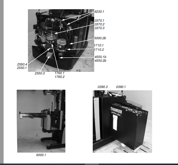
IMAGES PREVIEW OF THE MANUAL:
TOYOTA BT OME100H/HC OME120HW/HWC REPAIR MANUAL 7537426-040 – PDF DOWNLOAD:
PLEASE NOTE:
- This is the same manual used by the dealers to diagnose and troubleshoot your vehicle
- You will be directed to the download page as soon as the purchase is completed. The whole payment and downloading process will take anywhere between 2-5 minutes
- Need any other service / repair / parts manual, please feel free to contact [email protected] . We still have 50,000 manuals unlisted
S.V