Toyota BT OME100N OME100NW Repair Manual 7538996-040 – PDF DOWNLOAD
Original price was: $86.95.$27.95Current price is: $27.95.
Toyota BT OME100N OME100NW Repair Manual 7538996-040 – PDF DOWNLOAD
Description
Toyota BT OME100N OME100NW Repair Manual 7538996-040 – PDF DOWNLOAD
DESCRIPTION:
Toyota BT OME100N OME100NW Repair Manual 7538996-040 – PDF DOWNLOAD
General introduction
How to use this manual
The repair manual is divided into chapters containing the following
information:
• Operation and connection sequences – This chapter provides basic
description of the main truck functions
• Parameters – This chapter describes the parameters of the control system
and the calibration procedure
• Assembly and commissioning – This chapter describes the work required
to commission the truck
• Maintenance – This chapter includes an overall diagram for regular
maintenance followed by detailed descriptions of required maintenance
procedures
• Troubleshooting – The troubleshooting chapter describes the error codes
that are displayed when the truck is partially or completely disabled. It also
describes the cause of the problem together with suggested remedies.
• Remedies – This chapter describes the various truck systems, e.g. the
hydraulic system and includes descriptions of system parts and the
necessary service procedures. These descriptions are divided according
to TMHMS’s C Code system.
• Appendices – The appendices include:
Advice on scrapping
Information on electrical components and wiring diagrams
Hydraulics chart
List of tools needed
Information about general tightening torques
Oil and grease specifications
Technical data
TABLE OF CONTENTS:
Toyota BT OME100N OME100NW Repair Manual 7538996-040 – PDF DOWNLOAD
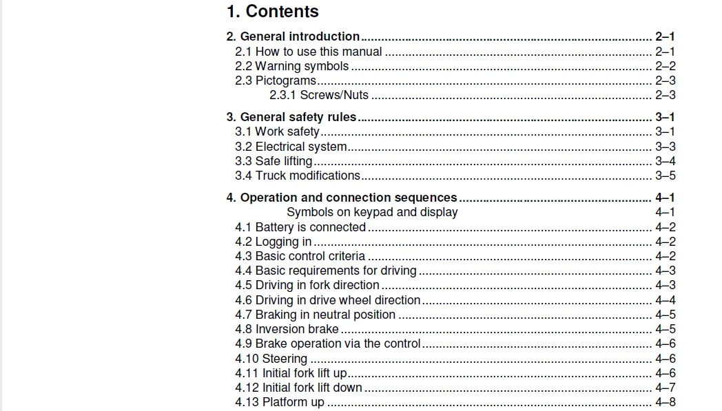
1 Contents 0
2 General introduction 0
2 1 How to use this manual 0
2 2 Warning symbols 0
2 3 Pictograms 0
2 3 1 Screws/Nuts 0
3 General safety rules 0
3 1 Work safety 0
3 2 Electrical system 0
3 3 Safe lifting 0
3 4 Truck modifications 0
4 Operation and connection sequences 0
Symbols on keypad and display 0
4 1 Battery is connected 0
4 2 Logging in 0
4 3 Basic control criteria 0
4 4 Basic requirements for driving 0
4 5 Driving in fork direction 0
4 6 Driving in drive wheel direction 0
4 7 Braking in neutral position 0
4 8 Inversion brake 0
4 9 Brake operation via the control 0
4 10 Steering 0
4 11 Initial fork lift up 0
4 12 Initial fork lift down 0
4 13 Platform up 0
4 14 Platform down 0
4 15 Driving in the drive wheel direction with walk buttons 0
4 16 Brake operation via the walking buttons 0
4 17 Fork lift via walking buttons 0
4 18 Fork lowering via walking buttons 0
5 Parameters, menu navigation and calibration 0
5 1 General 0
Symbols on keypad and display 0
5 1 1 Menu navigation 0
5 1 2 Show hour meter values 0
5 1 3 Show part numbers for software/hardware 0
5 2 Parameter settings 0
5 2 1 Copying the truck’s configurations 0
5 2 2 Setting operator/service parameters without using PC/PDA 0
5 2 3 Operator parameters 0
Overview 0
Factory preset operator parameters 0
Description of operator parameters 0
5 2 4 Service parameters 0
Overview 0
Description of service parameters 0
Verifying parameter settings for freely ventilated batteries (lead-acid batteries) 0
5 2 5 Factory parameters 0
Factory parameters no 1003 to 1042 – configurable optional functions 0
5 3 Calibration 0
5 3 1 Steering servo calibration 0
5 3 2 Hydraulic calibration 0
6 Installation and commissioning 0
6 1 Transporting the truck 0
6 2 Transporting the mast 0
6 3 Safe lifting 0
6 4 Battery installation 0
6 4 1 Safety for battery handling 0
6 4 2 Installing the battery 0
Battery indicator 0
6 5 Using PIN codes 0
6 5 1 General 0
6 5 2 Programming PIN codes 0
6 5 3 Default PIN codes 0
6 6 Setting parameters 0
6 6 1 Setting collision sensor parameters (option) 0
Collision sensor parameters 105 and 106 0
Programming the truck reset PIN code 0
6 6 2 Setting battery parameters 0
6 7 Function check 0
7 Maintenance 0
7 1 Introduction 0
7 2 Maintenance instructions 0
7 2 1 Cleaning and washing 0
7 2 2 High-pressure washers 0
7 2 3 Degreasing agents 0
7 2 4 Cleaning the exterior 0
7 2 5 Cleaning the chain 0
7 2 6 Cleaning the motor compartment 0
7 2 7 Electric components 0
7 3 Checking normal truck functionality 0
7 4 Safety check 0
7 5 First service 0
7 6 Maintenance schedule 0
7 6 1 Maintenance service every 500 operating hours/6 months 0
7 6 2 Maintenance service every 1000 operating hours/12 months 0
7 6 3 Maintenance service every 3000 operating hours/36 months 0
8 Troubleshooting 0
8 1 Towing a defective truck 0
Tow using a tow truck and tow wagon: 0
8 2 Auxiliary functions 0
8 2 1 Emergency driving mode 0
8 2 2 Error code history 0
8 3 Error code system 0
8 4 Error codes 0
8 5 Built-in test function for the tiller arm 0
8 5 1 Display test 0
8 5 2 Speed control 0
8 5 3 Controls for lifting/lowering 0
8 5 4 Sensilift 0
8 5 5 Keypad 0
8 6 Built-in test function 0
8 7 Digital input/output status 0
8 7 1 Test mode “2” – 0
8 7 2 Test mode “8” – Expansion unit SEU (option) 0
9 Chassis – C0000 0
9 1 Signs, warnings, adhesive labels – C0850 0
10 Motors – C1700 0
10 1 Pump motor – C1710 0
10 1 1 General 0
10 1 2 Replacing the pump motor 0
10 2 Steering motor – C1730 (steering servo assembly) 0
10 2 1 General 0
10 2 2 Replacing the steering servo 0
10 2 3 Gear replacement 0
10 3 Drive motor – C1760 0
10 3 1 General 0
10 3 2 Tightening torques – Drive motor 0
10 3 3 Component overview – Drive motor 0
10 3 4 Removing the drive motor 0
10 3 5 Fitting the drive motor 0
10 3 6 Replacing the temperature sensor 0
10 3 7 Replacing the RPM sensor 0
10 3 8 Replacing the speed sensor toothed wheel 0
10 3 9 Disassembly 0
10 3 10 Cleaning 0
10 3 11 Replacing the upper bearing 0
10 3 12 Replacing the lower bearing 0
10 3 13 Assembly 0
11 Drive gear – C2000 0
11 1 General 0
11 2 Component description – Drive gear 0
11 3 Service and repairs with the drive gear still in the truck 0
11 3 1 Checking and changing oil 0
11 3 2 Replacing studs 0
11 4 Repairs with the drive gear removed 0
11 4 1 Removing/fitting the drive gear 0
11 4 2 Replacing the drive shaft seal 0
11 4 3 Sealing the upper cover 0
11 4 4 Replacing the primary gear 0
12 Brake system/wheels – C3000 0
12 1 General 0
12 2 Parking brake – C3370 0
12 2 1 Checking the parking brake air gap 0
12 2 2 Removing/fitting the parking brake 0
12 2 3 Cleaning the parking brake 0
12 2 4 Releasing the parking brake 0
12 3 Drive wheel – C3530 0
12 3 1 Component overview 0
12 3 2 Replacing the drive wheel 0
12 4 Support wheel – C3500 0
12 4 1 Component overview 0
12 4 2 Replacing the wheel 0
12 5 Wheel wear 0
13 Steering system – C4000 0
13 1 General 0
13 2 Component overview 0
13 3 Steering unit – C4110 0
13 3 1 Calibration 0
13 3 2 Disassembling/assembling the steering unit handle 0
Disassembly 0
Assembly 0
13 3 3 Replacing the potentiometer [R2] 0
13 3 4 Replacing the inductive brake sensor [S10] 0
13 3 5 Replacing the damper 0
13 3 6 Checking and replacing the lateral movement line (Ergo version) 0
13 3 7 Replacing buttons in the tiller arm handle 0
Signal button/switch 0
Lift/lower button 0
Push button 0
13 4 Reference sensor – C4350 0
13 4 1 Replacing steering reference sensor [S65] 0
13 5 Steering bearing – C4380 0
13 5 1 Replacing the steering bearing 0
14 Electrical system – C5000 0
14 1 Battery C5110 0
14 1 1 Changing the battery 0
Battery installation/replacement using a battery changing table 0
Installation/replacement of a attery using a lifting device 0
14 1 2 Charging the battery 0
14 1 3 Limitations in performance depending on battery status 0
14 2 Contactor C5190 0
14 2 1 Replacing the contactor [Q10] 0
14 3 ACT/ACC regulators C5460 0
14 3 1 General 0
14 3 2 Replacing the transistor regulator 0
14 3 3 Replacing the transistor regulator cooling fan 0
15 Hydraulic system – C6000 0
15 1 General 0
15 2 Hydraulics unit 0
15 2 1 Cleaning 0
15 2 2 Packaging 0
15 2 3 Handling 0
15 2 4 Storage 0
15 2 5 Work procedures 0
15 3 Component overview – Hydraulic system 0
15 3 1 Overview OME100NW 0
15 3 2 Overview OME100N 0
15 4 Operating pressure 0
15 5 Reducer valve 0
15 6 Hose rupture valve 0
15 7 Pressure sensor 0
15 8 Hydraulic unit – C6100 0
15 8 1 Overview 0
15 8 2 Hydraulic unit tightening torques 0
15 8 3 Draining the hydraulic tank 0
15 8 4 Filling the tank 0
15 9 Removing/installing the hydraulic unit 0
15 9 1 Replacing valves 0
15 10 Adjusting the reducer valve 0
15 11 Hydraulic calibration 0
15 12 Hydraulic system, bleeding 0
15 13 Hydraulic couplings C6230 0
15 13 1 Tightening torques for hydraulic couplings 0
Conical coupling with O–ring 0
Trendo sealing 0
Pipe coupling 0
Coupling set in aluminium 0
Coupling set in steel 0
15 13 2 Quick change connector 0
Overview 0
Connecting the quick change connector 0
Disconnecting the quick change connector 0
15 14 Hydraulic cylinders – C6600 0
15 14 1 Replacing lifting cylinders 0
16 Mast/Lift system – C7000 0
16 1 Lifting chain system – C7220 0
16 1 1 Adjustment 0
16 1 2 Inspecting the chain 0
Noise 0
Surface rust 0
Rusty links 0
Stiff links 0
Bolt rotation 0
Loose bolts 0
Outline wear 0
Stretching 0
Damage 0
Damaged plates 0
Damaged bolts 0
Dirty chain 0
16 1 3 Cleaning 0
16 1 4 Lubrication 0
16 1 5 Adjusting the initial lift chain (OME100N) – C7220 0
16 2 Fork carriage – C7130/C7420 0
16 2 1 General – Fork carriage 0
Inspection 0
Fork height 0
16 2 2 Component overview 0
OME100NW – C7130 0
OME100N – C7130/C7420 0
16 2 3 Removing/fitting the cage/fork carriage (OME100NW) – C7130 0
16 2 4 Removing/fitting the cage/fork carriage (OME100N) – C7130 0
16 2 5 Initial lift – Removing/fitting the fork yoke (OME100N) – C7420 0
Dismantling 0
Mounting 0
16 3 Forks – C7410 0
16 3 1 Overview 0
General 0
Inspection 0
Inspection intervals 0
Surface cracks 0
Difference in height between the fork tips 0
Position lock 0
Marking legibility 0
Fork blade and fork carriage back 0
Mounting fixtures on the fork 0
16 3 2 Forks, repairs and testing 0
Repairs 0
Testing the yield point 0
17 Option – C9000 0
17 1 Spider expansion unit 0
17 2 T W I S Toyota Wireless Information System 0
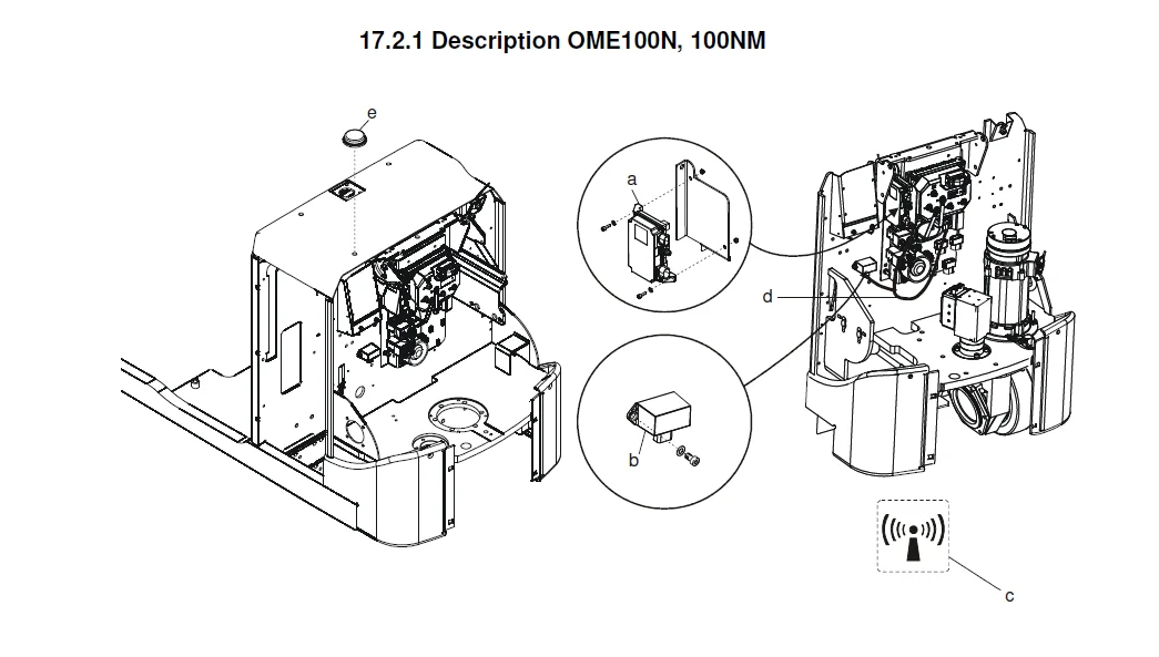
17 2 1 Description OME100N, 100NM 0
17 2 2 Component list 0
17 2 3 Drilling instructions 0
17 2 4 Method 0
17 3 E-bar 0
17 3 1 Overview 0
17 3 2 Component list E-bar 0
17 3 3 Replacement/installation method 0
17 3 4 E-bar accessories 0
18 Advice on scrapping 0
18 1 General 0
18 2 Marking of plastics 0
18 2 1 General marking of products and packaging 0
18 2 2 Markings according to the manufacturer’s standards 0
Abbreviations 0
Marking examples 0
18 3 Pressure vessels 0
18 3 1 Gas struts 0
18 4 Sorting categories 0
19 Electric components and wiring diagrams 0
19 1 Electric components 0
19 1 1 Electrical components – Overview 0
19 2 Electric wiring diagrams 0
19 2 1 List of symbols 0
19 2 2 Wiring diagram OME100N/NW – Overview 0
19 2 3 Wiring diagram OME100N/NW 0
20 Hydraulics schematics 0
20 1 Schematics OME100NW 0
20 2 Schematics OME100N 0
21 Tools 0
21 1 Super Seal connectors 0
21 2 AMP connectors 0
21 3 AMP connectors, Multilock series 040 0
21 4 Molex connectors 0
21 5 CPC contacts 0
21 6 MQS contacts 0
21 7 Grease guns 0
21 8 Other tools 0
22 Service data and grease specifications 0
22 1 General tightening torques 0
22 1 1 Galvanised, non-oiled screws 0
22 1 2 Untreated, oiled bolts 0
22 2 Lubrication chart 0
22 3 Oil and grease specification 0
23 Technical data 0
23 1 Basic data 0
23 2 Speed limitation 0
IMAGES PREVIEW OF THE MANUAL:
TOYOTA BT OME100N OME100NW REPAIR MANUAL 7538996-040 – PDF DOWNLOAD:
PLEASE NOTE:
- This is the SAME exact manual used by your dealers to fix your vehicle.
- The same can be yours in the next 2-3 mins as you will be directed to the download page immediately after paying for the manual.
- Any queries / doubts regarding your purchase, please feel free to contact [email protected]
S.V