Toyota BT OSE120 OSE120P OSE250 OSE250P Repair Manual 7536388-040 – PDF DOWNLOAD
Original price was: $89.95.$28.95Current price is: $28.95.
Toyota BT OSE120 OSE120P OSE250 OSE250P Repair Manual 7536388-040 – PDF DOWNLOAD
Description
Toyota BT OSE120 OSE120P OSE250 OSE250P Repair Manual 7536388-040 – PDF DOWNLOAD
DESCRIPTION:
Toyota BT OSE120 OSE120P OSE250 OSE250P Repair Manual 7536388-040 – PDF DOWNLOAD
General introduction
How to use this manual
The repair manual is divided into chapters containing the following
information:
• Operation and connection sequences – This chapter provides a basic
description of the main functions of the truck
• Parameters – This chapter describes steering system parameters and the
calibration procedure
• Installation and commissioning – This chapter describes the work that is
necessary for commissioning of the truck
• Maintenance – This chapter includes a general diagram for regular
maintenance followed by detailed descriptions of required maintenance
procedures
• Troubleshooting – The troubleshooting chapter describes the error codes
that are displayed when the truck is partially or completely disabled. It also
describes the cause of the problem together with suggested remedies.
• Remedies – This chapter describes the various truck systems, e.g. the
hydraulic system and includes descriptions of system parts and the
necessary service procedures. The various descriptions are divided
according to the C code system of the truck manufacturer.
• Appendices – The appendices include:
Instructions for disposal
Information about electrical components and wiring diagrams
Hydraulics diagram
List of required tools
Information about general tightening torques
Oil and grease specifications
Technical data
TABLE OF CONTENTS:
Toyota BT OSE120 OSE120P OSE250 OSE250P Repair Manual 7536388-040 – PDF DOWNLOAD
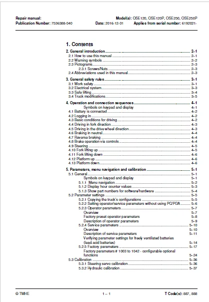
1 Contents 0
2 General introduction 0
2 1 How to use this manual 0
2 2 Warning symbols 0
2 3 Pictograms 0
2 3 1 Screws/Nuts 0
2 4 Abbreviations used in this manual 0
3 General safety rules 0
3 1 Work safety 0
3 2 Electrical system 0
3 3 Safe lifting 0
3 4 Truck modifications 0
4 Operation and connection sequences 0
Symbols on keypad and display 0
4 1 Battery is connected 0
4 2 Logging in 0
4 3 Basic conditions for driving 0
4 4 Driving in fork direction 0
4 5 Driving in the drive wheel direction 0
4 6 Braking in neutral 0
4 7 Reverse braking 0
4 8 Brake operation via controls 0
4 9 Steering 0
4 10 Fork lifting up 0
4 11 Fork lifting down 0
4 12 Platform up 0
4 13 Platform down 0
5 Parameters, menu navigation and calibration 0
5 1 General 0
Symbols on keypad and display 0
5 1 1 Menu navigation 0
5 1 2 Display hour counter values 0
5 1 3 Show part numbers for software/hardware 0
5 2 Parameter settings 0
5 2 1 Copying the truck’s configurations 0
5 2 2 Setting operator/service parameters without using PC/PDA 0
5 2 3 Operator parameters 0
Overview 0
Factory preset operator parameters 0
Description of operator parameters 0
5 2 4 Service parameters 0
Overview 0
Description of service parameters 0
Verifying parameter settings for freely ventilated batteries (lead-acid batteries) 0
5 2 5 Factory parameters 0
Factory parameters # 1003 to 1042 – configurable optional functions 0
5 3 Calibration 0
5 3 1 Steering servo calibration 0
5 3 2 Hydraulic calibration 0
6 Installation and commissioning 0
6 1 Transporting the truck 0
6 2 Transporting the mast 0
6 3 Safe lifting 0
6 4 Battery installation 0
6 4 1 Safety for battery handling 0
6 4 2 Installing the battery 0
Battery indicator 0
6 5 Using PIN codes 0
6 5 1 General 0
6 5 2 Programming PIN codes 0
6 5 3 PIN code defaults 0
6 6 Setting parameters 0
6 6 1 Setting collision sensor parameters (option) 0
Collision sensor parameters 105 and 106 0
PIN code programming for truck reset 0
6 6 2 Setting battery parameters 0
6 7 Function check 0
7 Maintenance 0
7 1 Introduction 0
7 2 Maintenance instructions 0
7 2 1 Cleaning and washing 0
7 2 2 High-pressure washers 0
7 2 3 Degreasing agents 0
7 2 4 Cleaning the exterior 0
7 2 5 Cleaning the chain 0
7 2 6 Cleaning the motor compartment 0
7 2 7 Electric components 0
7 3 Checking normal truck function 0
7 4 Safety checks 0
7 5 First service 0
7 6 Maintenance schedule 0
7 6 1 Maintenance service every 500 operating hours/6 months 0
7 6 2 Maintenance service every 1000 operating hours/12 months 0
7 6 3 Maintenance service every 3000 operating hours/36 months 0
8 Troubleshooting 0
8 1 Towing a defective truck 0
Tow using a tow truck and tow wagon: 0
8 2 Auxiliary functions 0
8 2 1 Emergency driving mode 0
8 2 2 Error code history 0
8 3 Error code system 0
8 4 Error codes 0
8 5 Built-in test function for the tiller arm 0
8 5 1 Display test 0
8 5 2 Speed control 0
8 5 3 Controls for lifting/lowering 0
8 5 4 Sensilift 0
8 5 5 Keypad 0
8 6 Built-in test function 0
8 7 Digital input/output status 0
8 7 1 Test mode “2” – 0
8 7 2 Test mode “8” – Expansion unit SEU (option) 0
9 Chassis – C0000 0
9 1 Details dampened floor 0
9 2 Adjust dampened floor 0
9 3 Platform with operator lift – C9130 0
9 3 1 Adjusting the side guides 0
9 3 2 Adjusting the outer side guides 0
9 3 3 Removing the platform with operator lift 0
9 3 4 Reinstalling the platform with operator lift 0
9 4 Automatic height adjustment – C9390 0
9 5 Signs, warnings, adhesive labels – C0850 0
10 Motors – C1700 0
10 1 Pump motor – C1710 0
10 1 1 General 0
10 1 2 Replacing the pump motor 0
10 2 Steering motor – C1730 (steering servo assembly) 0
10 2 1 General 0
10 2 2 Replacing the steering servo assembly 0
10 2 3 Gear replacement 0
10 3 Drive motor – C1760 0
10 3 1 General 0
10 3 2 Tightening torque – Drive motor 0
10 3 3 Component overview – Drive motor 0
10 3 4 Removing the drive motor 0
10 3 5 Fitting the drive motor 0
10 3 6 Replacing the temperature sensor 0
10 3 7 Replacing the RPM sensor 0
10 3 8 Replacing the speed sensor toothed wheel 0
10 3 9 Disassembly 0
10 3 10 Cleaning 0
10 3 11 Replacing the upper bearing 0
10 3 12 Replacing the lower bearing 0
10 3 13 Assembly 0
11 Drive gear – C2000 0
11 1 General 0
11 2 Component overview – drive gear 0
11 3 Service and repairs with the drive gear in the truck 0
11 3 1 Checking and changing the oil 0
11 3 2 Replacing studs 0
11 4 Repairs with transmission removed 0
11 4 1 Removing/fitting the drive gear 0
11 4 2 Replacing the drive shaft seal 0
11 4 3 Sealing the upper cover 0
11 4 4 Replacing the primary gear 0
12 Brake system/Wheels C3000 0
12 1 General 0
12 2 Parking brake – C3370 0
12 2 1 Checking the parking brake air gap 0
12 2 2 Removing/fitting the parking brake 0
12 2 3 Cleaning the parking brake 0
12 2 4 Releasing the parking brake 0
12 3 Drive wheel – C3530 0
12 3 1 Component overview 0
12 3 2 Replacing the drive wheel 0
12 4 Castor wheel – C3540 0
12 4 1 Component overview – Castor wheel 0
12 4 2 Castor wheel maintenance and inspection 0
Check 0
12 4 3 Adjusting castor wheel height 0
Adjustment 0
12 4 4 Replacing the castor wheel 0
Method for replacing the complete wheel 0
Method for replacing the wheel bearing 0
12 5 Fork wheels – C3550 0
12 5 1 Removing/fitting for wheel OSE250, OSE250P (bogie) 0
12 6 Wheel wear 0
13 Steering system – C4000 0
13 1 General 0
13 2 Component overview 0
13 3 Steering unit – C4110 0
13 3 1 Calibration 0
13 3 2 Disassembling/assembling the steering unit handle 0
Disassembly 0
Assembly 0
13 3 3 Disassembly/Assembly Replacing the potentiometer [R2] 0
13 3 4 Replacing the inductive brake sensor [S10] 0
13 3 5 Replacing the damper 0
13 3 6 Checking and replacing the lateral movement line (Ergo version) 0
13 3 7 Replacing buttons in the tiller arm handle 0
Signal button/switch 0
Lift/lower button 0
Push button 0
13 4 Reference sensor – C4350 0
13 4 1 Replacing steering reference sensor [S65] 0
13 5 Steering bearing – C4380 0
13 5 1 Replacing the steering bearing 0
14 Electrical system – C5000 0
14 1 Battery – C5110 0
14 1 1 Replacing the battery 0
Battery installation/replacement using a battery changing table 0
Battery installation/replacement using a lifting device 0
14 1 2 Charging the battery 0
14 1 3 Performance limitations due to battery status 0
14 2 Li-ion battery (Hoppecke) 0
14 2 1 Resetting/restarting the battery 0
14 3 Inspecting the battery 0
14 4 Contactor – C5190 0
14 4 1 Replacing the contactor [Q10] 0
14 5 ACT/ACC regulators – C5460 0
14 5 1 General 0
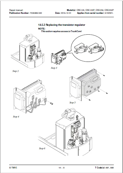
14 5 2 Replacing the transistor regulator 0
14 5 3 Replacing the transistor regulator cooling fan 0
15 Hydraulic system – C6000 0
15 1 General 0
15 2 Hydraulic cleanliness 0
15 2 1 Cleaning 0
15 2 2 Packaging 0
15 2 3 Handling 0
15 2 4 Storage 0
15 2 5 Work procedures 0
15 3 Component overview – Hydraulic system 0
15 3 1 Overview OSE250 0
15 3 2 Overview OSE120, OSE120P, OSE250P 0
15 4 Operating pressure 0
15 5 Pressure limiting valve 0
15 6 Hose rupture valve 0
15 7 Pressure sensor 0
15 8 Hydraulic unit – C6100 0
15 8 1 Overview 0
Overview OSE250 0
Description OSE250P, OSE120, OSE120P 0
15 8 2 Tightening torque for hydraulic unit 0
Tightening torques OSE250 0
Tightening torques OSE250P, OSE120, OSE120P 0
15 8 3 Emptying the hydraulic tank 0
15 8 4 Filling the tank 0
15 9 Removing/installing the hydraulic unit 0
15 9 1 Replacing valves 0
15 10 Adjusting the pressure limiting valve 0
15 10 1 Adjustment OSE250 0
15 10 2 Adjustment OSE250P, OSE120, OSE120P 0
15 11 Hydraulic calibration 0
15 12 Hydraulic system, bleeding 0
15 13 Hydraulic couplings C6230 0
15 13 1 Tightening torques for hydraulic connections 0
Tapered coupling with O-ring 0
Tredo seal 0
Pipe coupling 0
Coupling set in aluminium 0
Coupling set in steel 0
15 13 2 Quick change connector 0
Overview 0
Assembling the quick change connector 0
Dismantling the quick change connector 0
15 14 Main lift – C6610 0
15 14 1 Component overview 0
15 14 2 Removing the lift cylinder OSE120, OSE120P 0
15 14 3 Installing the lift cylinder OSE120, OSE120P 0
15 14 4 Removing lift cylinder OSE250 0
15 14 5 Installing the lifting cylinder OSE250 0
16 Mast/Lift system – C7000 0
16 1 Main lifting chain system C7120 0
16 1 1 Adjustment 0
16 1 2 Checking the chain 0
Noise 0
Surface rust 0
Rusty links 0
Stiff links 0
Bolt rotation 0
Loose bolts 0
Outline wear 0
Stretching 0
Damage 0
Damaged plates 0
Damaged bolts 0
Dirty chain 0
16 1 3 Cleaning 0
16 1 4 Lubrication 0
16 2 Fork carriage – C0380 0
16 2 1 General – Fork carriage 0
Checking 0
Fork height OSE250/250P 0
16 2 2 Component parts OSE250, OSE250P 0
16 2 3 Component parts OSE250, OSE250P 0
16 2 4 Front linkage on older machines 0
16 2 5 Install fork carriage OSE250, OSE250P 0
16 2 6 Roller replacement 0
16 2 7 Removing the fork carriage OSE250, OSE250P 0
16 3 Fork carriage – 7420 0
16 3 1 General – Fork carriage 0
Inspection 0
Fork height OSE250/250P 0
16 3 2 Removing the fork carriage 0
16 3 3 Install the fork carriage in the mast 0
16 3 4 Replacing the mast rollers 0
16 3 5 Checking fork carriage lateral clearance 0
17 Options – C9000 0
17 1 Spider expansion unit 0
17 2 Component overview, T W I S (Toyota Wireless Information System) 0
17 2 1 Overview OSE120 0
17 2 2 Component list 0
17 2 3 Overview OSE120P 0
17 2 4 Component list T W I S 0
17 2 5 Overview OSE250/250P 0
17 2 6 Component list T W I S 0
17 3 E-bar 0
17 3 1 Overview 0
17 3 2 Component list E-bar 0
17 3 3 Replacement/installation method 0
17 3 4 E-bar accessories 0
18 Instructions for disposal 0
18 1 General 0
18 2 Marking of plastics 0
18 2 1 General marking of products and packaging 0
18 2 2 Marking according to the manufacturer’s standards 0
Abbreviations 0
Marking examples 0
18 3 Pressure vessels 0
18 3 1 Gas struts 0
18 4 Sorting categories 0
19 Electrical components and electrical diagram 0
19 1 Electric components 0
19 1 1 Electric component overview 0
19 2 Electrical wiring diagrams 0
19 2 1 List of symbols 0
19 2 2 Wiring diagram 250P – Overview 0
19 2 3 Wiring diagram 250P 0
19 2 4 Wiring diagram 120P – Overview 0
19 2 5 Wiring diagram 120P 0
19 2 6 Wiring diagram 120 – Overview 0
19 2 7 Wiring diagram 120 0
19 2 8 Wiring diagram 250 – Overview 0
19 2 9 Wiring diagram 250 0
20 Hydraulics schematics 0
20 1 Schematics OSE120P 0
20 2 Schematics OSE120 0
20 3 Schematics OSE250P 0
20 4 Schematics OSE250 0
21 Tools 0
21 1 Super Seal connectors 0
21 2 AMP connectors 0
21 3 AMP connectors, Multilock series 040 0
21 4 Molex connectors 0
21 5 CPC contacts 0
21 6 MQS contacts 0
21 7 Grease guns 0
21 8 Other tools 0
22 Service data and grease specifications 0
22 1 General tightening torques 0
22 1 1 Galvanised, non-oiled screws 0
22 1 2 Untreated, oiled screws 0
22 2 Lubrication chart 0
22 3 Oil and grease specification 0
23 Technical data 0
23 1 Basic data 0
23 1 1 Speed limitation 0
IMAGES PREVIEW OF THE MANUAL:
TOYOTA BT OSE120 OSE120P OSE250 OSE250P REPAIR MANUAL 7536388-040 – PDF DOWNLOAD:
PLEASE NOTE:
- This is the SAME MANUAL used by the dealerships to diagnose your vehicle
- No waiting for couriers / posts as this is a PDF manual and you can download it within 2 minutes time once you make the payment.
- Your payment is all safe and the delivery of the manual is INSTANT – You will be taken to the DOWNLOAD PAGE.
- So have no hesitations whatsoever and write to us about any queries you may have : heydownloadss @gmail.com
S.V