Toyota Forklift 7BRU18 7BRU23 7BDRU15 7BSU20 7BSU25 Parts Catalog Manual – PDF DOWNLOAD
$28.95
Toyota Forklift 7BRU18 7BRU23 7BDRU15 7BSU20 7BSU25 Parts Catalog Manual – PDF DOWNLOAD
24 Volt Models S/N 21,000 and Up
36 Volt Models S/N 32,000 and Up
Description
Toyota Forklift 7BRU18 7BRU23 7BDRU15 7BSU20 7BSU25 Parts Catalog Manual – PDF DOWNLOAD
FILE DETAILS:
Toyota Forklift 7BRU18 7BRU23 7BDRU15 7BSU20 7BSU25 Parts Catalog Manual – PDF DOWNLOAD
Language : English
Pages : 276
Downloadable : Yes
File Type : PDF
IMAGES PREVIEW OF THE MANUAL:
DESCRIPTION:
Toyota Forklift 7BRU18 7BRU23 7BDRU15 7BSU20 7BSU25 Parts Catalog Manual – PDF DOWNLOAD
24 Volt Models S/N 21,000 and Up
36 Volt Models S/N 32,000 and Up
To Our Customer :
Figure 1-1: To Our Customer:
The Part Numbers in this Parts Catalog were correct at the time your truck was manufactured. It is our policy
to constantly improve our products, therefore, part numbers may continue to change. When ordering parts,
verify part numbers through your Dealer’s Parts Catalog, which is kept up to date. Also note that Illustrations
of assemblies and components may not necessarily conform to the exact installation as they appear on your
truck.
Tips for Ordering Parts:
In addition to Part Number and Description, have available:
• The model number and serial number of the truck
• Pertinent specifications such as mast height, battery voltage, drive motor type, etc.
• Pertinent name plate data
• Applicable installation or assembly numbers
• Accurate Part Number
Using This Catalog:
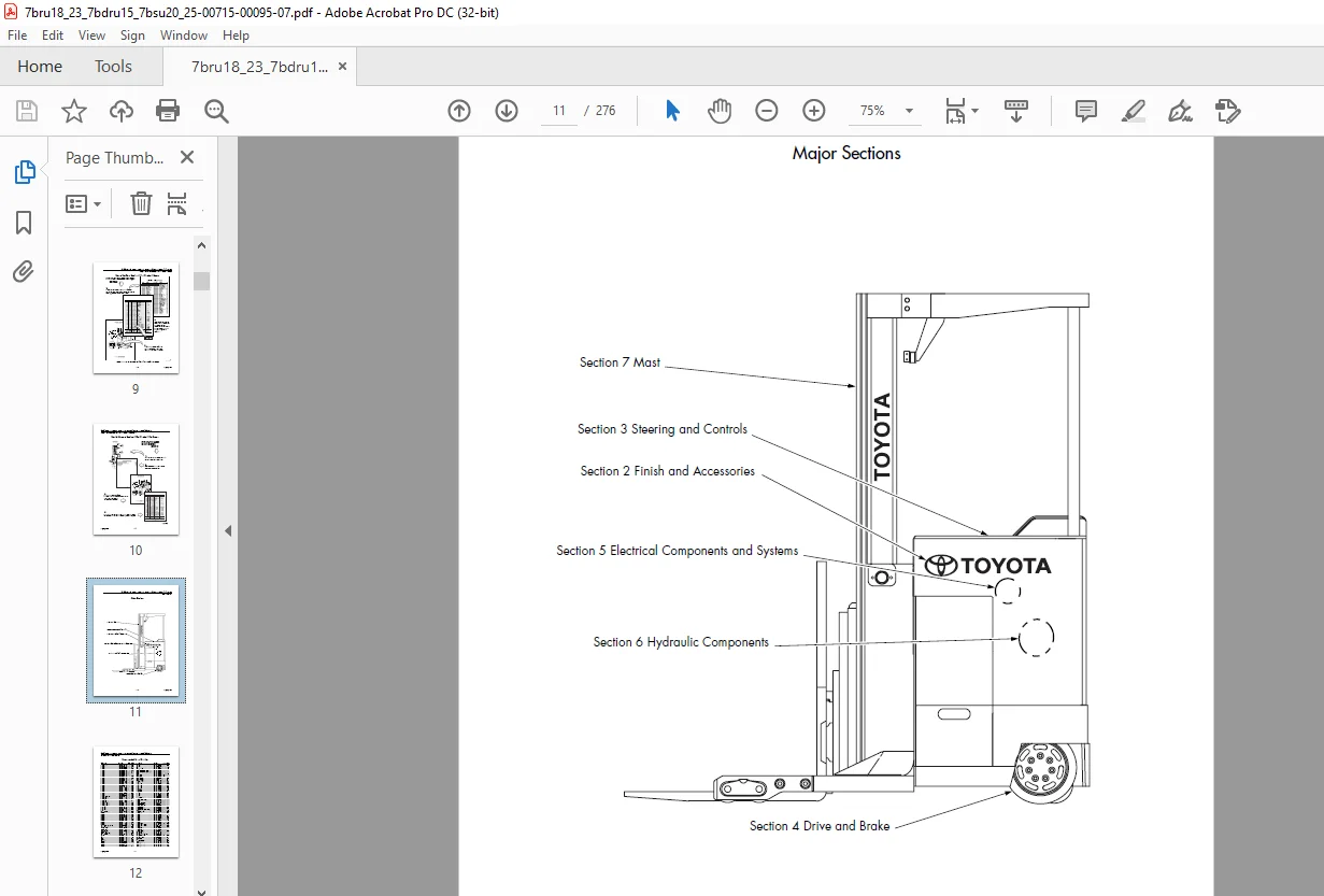
This Catalog contains navigational aids to help you locate specific parts information.
• Use Section 1 to decide where to start your search for information. The overall locator
views define the technical configuration of the Catalog and tie the figures in the
Catalog to the engineering database.
• Use the Table of Contents to locate assemblies and subassemblies by name.
• Use the Alphabetical Index (by Part Name) and the Numerical Index (by Part Number)
to locate individual parts.
Determine configuration differences with the “Used On” codes contained within the Parts List. The “Used
On” code attaches a part number to a wide range of design variables such as operating voltage, battery
size, steering type, mast height and extension speed, fork carriages, color and size of tires, guide wheel
specs, etc.
TABLE OF CONTENTS:
Toyota Forklift 7BRU18 7BRU23 7BDRU15 7BSU20 7BSU25 Parts Catalog Manual – PDF DOWNLOAD
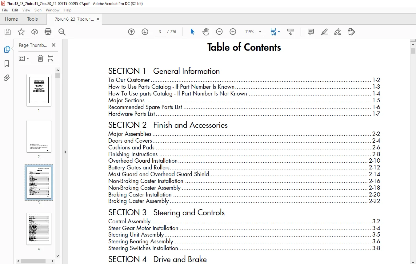
Front Cover................................................................  0
Table of Contents..........................................................  3
SECTION 1 General Information .............................................  7
	To Our Customer .......................................................  8
	How to Use Parts Catalog - If Part Number Is Known ....................  9
	How To Use parts Catalog - If Part Number Is Not Known ................ 10
	Major Sections ........................................................ 11
	Recommended Spare Parts List .......................................... 12
	Hardware Parts List ................................................... 13
SECTION 2 Finish and Accessories .......................................... 15
	Major Assemblies ...................................................... 16
	Doors and Covers ...................................................... 18
	Cushions and Pads ..................................................... 20
	Finishing Instructions ................................................ 22
	Overhead Guard Installation ........................................... 24
	Battery Gates and Rollers ............................................. 26
	Mast Guard and Overhead Guard Shield .................................. 28
	Non-Braking Caster Installation ....................................... 30
	Non-Braking Caster Assembly ........................................... 33
	Braking Caster Installation ........................................... 34
	Braking Caster Assembly ............................................... 36
SECTION 3 Steering and Controls ........................................... 39
	Control Assembly ...................................................... 40
	Steer Gear Motor Installation ......................................... 42
	Steering Unit Assembly ................................................ 43
	Steering Bearing Assembly ............................................. 44
	Steering Switches Installation ........................................ 46
SECTION 4 Drive and Brake ................................................. 49
	Drive Unit Installation ............................................... 50
	Transmission Assembly ................................................. 52
	Drive Wheel Assembly .................................................. 54
	Brake Pedal Assembly Without Caster Brake ............................. 56
	Brake Pedal Assembly With Caster Brake ................................ 58
	Drive Brake Assembly .................................................. 60
	Caster Brake Assembly ................................................. 62
SECTION 5 Electrical Components and Systems ............................... 63
	Electrical Assembly ................................................... 64
	Cold Storage Electrical Assembly ...................................... 70
	Controller, Electric Assembly ......................................... 74
	Contactor Assembly .................................................... 76
	Overhead Guard Plate Without Light and Fan Package .................... 77
	Overhead Guard Console Installation ................................... 79
	Light and Fan Assembly ................................................ 80
	Warning Light and Alarm Assembly ...................................... 82
	Working Light Installation ............................................ 84
	Auxiliary Switch Assembly ............................................. 85
	Control Handle Assembly ............................................... 86
	Floor Plate Assembly .................................................. 88
	Drive Motor, 24 Volt/36 Volt .......................................... 90
	Pump Motor (7BRU23, 7BDRU and 7BSU25) ................................. 92
	Motor, Pump (7BRU18 AND 7BSU20) ....................................... 94
SECTION 6 Hydraulic Components ............................................ 97
	Hydraulic Installation, Tractor ....................................... 98
	Reservoir Assembly ....................................................100
	Main Manifold Assembly ................................................102
	Lift/Lower Manifold Assembly ..........................................104
	Reach/Auxiliary Manifold Assembly .....................................106
	Manifold Assembly, Scissors ...........................................108
	Manifold Assembly, Straddle ...........................................111
	Pump and Motor Installation ...........................................112
	Staging Cylinder (Models 7BRU18 and 7BSU20) ...........................114
	Staging Cylinder (Models 7BRU23, 7BDRU15 and 7DSU25) ..................118
	Cylinder Assembly, Free Lift (7BRU18 and 7BSU20) ......................122
	Cylinder Assembly, Free Lift (Models 7BRU23, 7BDRU15 and 7BSU25) ......124
	Reach Cylinder Assembly (Model 7BRU18) ................................128
	Reach Cylinder Assembly (Model 7BRU23) ................................130
	Reach Cylinder Assembly (Model 7BDRU15) ...............................132
	Tilt Cylinder Assembly (Models 7BRU18, 7BSU20 and 7BSU25) .............134
	Tilt Cylinder Assembly (Model 7BRU23) .................................136
	Tilt Cylinder (Model 7BDRU15) .........................................138
	Lift Cylinder Plumbing (Models 7BRU18 and 7BSI20) .....................140
	Lift Cylinder Plumbing (Models 7BRU23, 7BDRU15 and 7BSU25) ............142
	Triline Hoses (Models 7BRU18 and 7BSU20) ..............................144
	Triline Hoses (Models 7BRU23, 7BDRU15 and 7BSU25) .....................146
	Carriage Supply Lines (Model 7BSU20) ..................................148
	Carriage Supply Lines (Model 7BSU25) ..................................150
	Reach Supply Lines (Model 7BRU18) .....................................152
	Reach Supply Lines (Model 7BRU23) .....................................154
	Double Reach Supply Lines (Model 7BDRU15) .............................156
	Reach Cylinder Piping (Model 7BRU18) ..................................158
	Reach Cylinder Piping (Model 7BRU23) ..................................159
	Double Reach Cylinder Piping (Model 7BDRU15) ..........................160
	Tilt Cylinder Piping (Model 7BSU20) ...................................162
	Tilt Cylinder Piping (Model 7BSU25) ...................................164
	Tilt Cylinder Piping (Model 7BRU18) ...................................166
	Tilt Cylinder Piping (Model 7BRU23) ...................................168
	Tilt Cylinder Piping (Model 7BDRU15) ..................................170
	Sideshift Cylinder Piping (Model 7BSU20) ..............................172
	Sideshift Cylinder Piping (Model 7BSU25) ..............................173
	Sideshift Cylinder Piping (Model 7BRU18) ..............................174
	Sideshift Cylinder Piping (Model 7BRU23) ..............................175
	Sideshift Cylinder Piping (Model 7BDRU15) .............................176
SECTION 7 Mast ............................................................179
	Mast Pivot Retainer ...................................................180
	Mast Assembly (Models 7BRU18 and 7BSU20) ..............................182
	Mast Assembly (Models 7BRU23, 7BDRU15 and 7BSU25) .....................186
	Pulley Bracket Assembly (Models 7BRU18 and 7BSU20) ....................190
	Pulley Bracket Assembly (Models 7BRU23, 7BDRU15 and 7BSU25) ...........192
	Carriage3 Assembly (Model 7BSU20) .....................................194
	Carriage Assembly (Model 7BSU25) ......................................196
	Reach Carriage Assembly (Model 7BRU18) ................................198
	Reach Carriage Assembly (Model 7BRU23) ................................202
	Reach Carriage Assembly (Model 7BDRU15) ...............................206
	Sideshift Assembly (All) ..............................................210
	Toe Box Assembly (4 in. X 3 in.) Closed Toe ...........................212
	Toe Box Assembly (5 in. X 4 in.) Closed Toe ...........................214
	Toe Box Assembly (4 in. X 3 in.) Open Toe .............................216
	Toe Box Assembly (5 in. X 3 in.) Open Toe .............................218
	Toe Box Assembly (5 in. X 4 in.) Open Toe .............................220
	Toe Box Assembly (10 in. X 3.5 in.) ...................................222
	Fork Assembly .........................................................223
SECTION 8 Options/Kits ....................................................225
	Fire Extinguisher Installation ........................................226
	Load Backrest Installation (Models 7BRU18, 7BSU20 and 7BSU25) .........228
	RF Power Hookup .......................................................229
	Height Indicator (Models 7BRU18 and 7BSU20) ...........................230
	Height Indicator (Models 7BRU23, 7BSU25 and 7BDRU15) ..................232
	Weight Display ........................................................234
	Cooling Fan, Drive Motor ..............................................235
	Lift Limit Switch Installation (Models 7BRU18 and 7BSU20) .............236
	Lift Limit Switch Installation (Models 7BRU23, 7BDRU15 and 7BSU25) ....239
APPENDIX A Alphabetical Parts Index .......................................243
APPENDIX B Numerical Parts Index ..........................................261
Questions? Email us: [email protected]
PLEASE NOTE:
- This is not a physical manual but a digital manual – meaning no physical copy will be couriered to you. The manual can be yours in the next 2 mins as once you make the payment, you will be directed to the download page IMMEDIATELY.
- This is the same manual used by the dealers inorder to diagnose your vehicle of its faults.
- Require some other service manual or have any queries: please WRITE to us at [email protected]
S.V