Toyota Forklift 7FBRE12 7FBRE12C 7FBRE14 7FBRE14C 7FBRE16 7FBRE16C 7FBRE20 7FBRE20C 7FBRE25 7FBRE25C Service Manual 423260
$30.95
Toyota Forklift 7FBRE12 7FBRE12C 7FBRE14 7FBRE14C 7FBRE16 7FBRE16C 7FBRE20 7FBRE20C 7FBRE25 7FBRE25C Service Manual 423260 – PDF DOWNLOAD
Description
Toyota Forklift 7FBRE12 7FBRE12C 7FBRE14 7FBRE14C 7FBRE16 7FBRE16C 7FBRE20 7FBRE20C 7FBRE25 7FBRE25C Service Manual 423260 – PDF DOWNLOAD
FILE DETAILS:
Toyota Forklift 7FBRE12 7FBRE12C 7FBRE14 7FBRE14C 7FBRE16 7FBRE16C 7FBRE20 7FBRE20C 7FBRE25 7FBRE25C Service Manual 423260 – PDF DOWNLOAD
Language : English
Pages : 596
Downloadable : Yes
File Type : PDF
IMAGES PREVIEW OF THE MANUAL:
DESCRIPTION:
Toyota Forklift 7FBRE12 7FBRE12C 7FBRE14 7FBRE14C 7FBRE16 7FBRE16C 7FBRE20 7FBRE20C 7FBRE25 7FBRE25C Service Manual 423260 – PDF DOWNLOAD
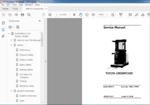
- TOYOTA’s reach truck program is intended for handling pallets indoors or alternatively other
types of loads using other load carriers. The trucks are operated seated in a protected and
ergonomic operator posi- tion. The reach trucks are available in different size classes and have as
standard a lifting capacity of up to 2500 kg and a lifting height of up to 10.5 m. - The trucks are equipped with a 48 V electrical system. The travel and lifting speeds are transistor
controlled to provide smooth operations. In addition, the travel function and the different
hydraulic functions have additional controls which further enhance these features. Different
speeds and steering can be set using parameters to give the best pos- sible individual setting for
the functions.
Application areas for TOYOTA’s reach trucks:
TOYOTA’s reach trucks are solely designed and manufactured to han- dle goods. The trucks should be
fitted with the appropriate accessories relevant to the application.
Prohibited applications for TOYOTA’s reach trucks:
TOYOTA’s reach trucks are designed for handling goods indoors. Unless the truck is
specially equipped, it is not permitted to use the truck for other purposes including the following
applications:
– In areas that contain dust or gases which can cause fires or ex- plosions
– As a tow-truck for trailers
– To tow other trucks
– To transport/lift passengers
– To drive on gravel or grass
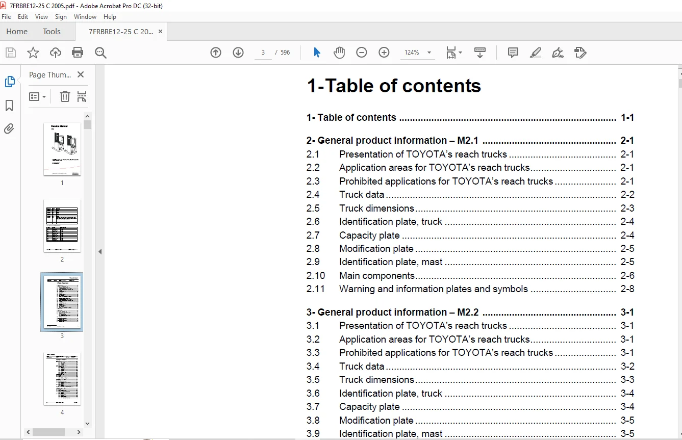
TABLE OF CONTENTS:
Toyota Forklift 7FBRE12 7FBRE12C 7FBRE14 7FBRE14C 7FBRE16 7FBRE16C 7FBRE20 7FBRE20C 7FBRE25 7FBRE25C Service Manual 423260 – PDF DOWNLOAD
1- Table of contents...........................................................................................  3
2- General product information - M2.1.......................................................................... 21
	2.1 Presentation of TOYOTA’s reach trucks.................................................................. 21
	2.2 Application areas for TOYOTA’s reach trucks............................................................ 21
	2.3 Prohibited applications for TOYOTA’s reach trucks...................................................... 21
	2.4 Truck data............................................................................................. 22
	2.5 Truck dimensions....................................................................................... 23
	2.6 Identification plate, truck............................................................................ 24
	2.7 Capacity plate......................................................................................... 24
	2.8 Modification plate..................................................................................... 25
	2.9 Identification plate, mast............................................................................. 25
	2.10 Main components....................................................................................... 26
	2.11 Warning and information plates and symbols............................................................ 28
3- General product information - M2.2.......................................................................... 29
	3.1 Presentation of TOYOTA’s reach trucks.................................................................. 29
	3.2 Application areas for TOYOTA’s reach trucks............................................................ 29
	3.3 Prohibited applications for TOYOTA’s reach trucks...................................................... 29
	3.4 Truck data............................................................................................. 30
	3.5 Truck dimensions....................................................................................... 31
	3.6 Identification plate, truck............................................................................ 32
	3.7 Capacity plate......................................................................................... 32
	3.8 Modification plate..................................................................................... 33
	3.9 Identification plate, mast............................................................................. 33
	3.10 Main components....................................................................................... 34
	3.11 Warning and information plates and symbols............................................................ 36
4- Technical data - M4.1....................................................................................... 37
5- Technical data - M4.2....................................................................................... 41
6- Introduction, maintenance - P1.............................................................................. 45
	6.1 Safety regulations with maintenance work............................................................... 45
	6.2 Cleaning and washing................................................................................... 46
		6.2.1 External cleaning................................................................................ 47
		6.2.2 Cleaning the motor compartment................................................................... 47
		6.2.3 Electrical components............................................................................ 47
	6.3 Safe lifting........................................................................................... 48
7- Preventive Maintenance - P2.1............................................................................... 49
	7.1 Maintenance chart...................................................................................... 49
8- Preventive Maintenance - P2.2............................................................................... 59
	8.1 Maintenance chart...................................................................................... 59
9- Oil and grease specification - P3........................................................................... 69
10- Tools -P4.................................................................................................. 71
	10.1 Super Seal............................................................................................ 71
		10.1.1 AMP connector................................................................................... 72
		10.1.2 AMP microtimer.................................................................................. 73
		10.1.3 Diverse tools................................................................................... 74
11- Cab heating/ventilation - 0630............................................................................. 81
	11.1 Air conditioning unit................................................................................. 81
		11.1.1 Ventilation..................................................................................... 81
		11.1.2 Main heater..................................................................................... 81
		11.1.3 Auxiliary heater................................................................................ 81
		11.1.4 Temperature..................................................................................... 81
		11.1.5 Air direction................................................................................... 82
		11.1.6 Fuses........................................................................................... 82
		11.1.7 Air filter...................................................................................... 82
		11.1.8 Emergency exit (12)............................................................................. 83
		11.1.9 Lighting........................................................................................ 83
12- Driver Protection - 0840................................................................................... 85
	12.1 General............................................................................................... 85
	12.2 Tilt Stops............................................................................................ 86
		12.2.1 Inspection and Adjustment....................................................................... 86
		12.2.2 Removing the tilt stops......................................................................... 87
13- Electric pump motor - 1710.1............................................................................... 89
	13.1 General............................................................................................... 89
	13.2 Dismantling the pump motor............................................................................ 89
	13.3 Dismantling and assembling the pump motor............................................................. 90
		13.3.1 Dismantling..................................................................................... 90
		13.3.2 Assembling...................................................................................... 91
	13.4 Bearing replacement................................................................................... 92
		13.4.1 Dismantling..................................................................................... 92
		13.4.2 Assembling...................................................................................... 93
	13.5 Installation instructions for external temperature sensor............................................. 94
14- Electric Pump Motor - 1710.2............................................................................... 97
	14.1 General............................................................................................... 97
	14.2 Dismantling the Pump Motor............................................................................ 97
		14.2.1 Connection...................................................................................... 97
	14.3 Removing and Replacing the Pump Motor................................................................. 98
		14.3.1 Dismantling..................................................................................... 98
		14.3.2 Assembling...................................................................................... 99
	14.4 Bearing replacement................................................................................... 99
		14.4.1 Dismantling (D side)............................................................................100
		14.4.2 Assembling......................................................................................100
		14.4.3 Dismantling (N side)............................................................................100
		14.4.4 Assembling (N side).............................................................................101
		14.4.5 Carbon brushes and brush holders................................................................101
			Commutator.........................................................................................101
			Machining the commutator...........................................................................101
15- Electric Steering Motor - 1730.............................................................................103
	15.1 General...............................................................................................103
	15.2 Replacing the Steering Motor..........................................................................103
		15.2.1 Dismantling.....................................................................................103
		15.2.2 Assembling......................................................................................103
	15.3 Removing and replacing the carbon brushes.............................................................104
16- Electric drive motor - 1760................................................................................105
	16.1 General...............................................................................................105
	16.2 Dismantling the drive motor...........................................................................105
	16.3 Dismantling and assembling the drive motor............................................................106
		16.3.1 Dismantling the drive motor.....................................................................106
			Removing the gear wheel............................................................................106
			Removing the brakes................................................................................106
		16.3.2 Assembling the drive motor......................................................................107
			Assembling the gear wheel..........................................................................107
	16.4 Bearing replacement...................................................................................108
		16.4.1 Dismantling.....................................................................................108
			D-side.............................................................................................108
		16.4.2 Assembling......................................................................................109
			N-side.............................................................................................109
			D-side.............................................................................................109
	16.5 Installation instructions for external temperature sensor.............................................110
17- Mechanical drive gear unit - 2550..........................................................................113
	17.1 General...............................................................................................113
	17.2 Components/data for the drive assembly/transmission...................................................113
		17.2.1 Component placement.............................................................................114
		17.2.2 Technical data..................................................................................115
		17.2.3 Dismantling the transmission....................................................................116
	17.3 Replacing the drive motor/drive transmission..........................................................117
		17.3.1 Dismantling the drive motor.....................................................................117
		17.3.2 Dismantling the drive transmission..............................................................118
		17.3.3 Assembling the transmission.....................................................................118
		17.3.4 Installing the drive motor......................................................................119
			Assembling the gear wheel..........................................................................119
	17.4 Checking/replacing the oil............................................................................120
		17.4.1 Checking/refilling the oil......................................................................120
		17.4.2 Changing the Oil................................................................................120
	17.5 Repairs...............................................................................................121
		17.5.1 Replacing the drive shaft sealing ring..........................................................121
			Dismantling........................................................................................121
			Assembling.........................................................................................122
		17.5.2 Leakage from the upper cover....................................................................123
		17.5.3 Leakage from the lower cover....................................................................123
		17.5.4 Replacing wheel bolts...........................................................................124
18- Travel brake system - 3100.1...............................................................................125
	With support arm brake.....................................................................................125
	18.1 General...............................................................................................125
	18.2 Operating description.................................................................................125
		18.2.1 Releasing the accelerator.......................................................................126
		18.2.2 Travel direction selector.......................................................................126
		18.2.3 Pressing down the brake pedal...................................................................126
		18.2.4 Parking brake...................................................................................126
		18.2.5 Emergency braking...............................................................................127
	18.3 Electromechanical disc brake, drive motor.............................................................128
		18.3.1 Assembling......................................................................................128
		18.3.2 Dismantling.....................................................................................129
		18.3.3 Inspection......................................................................................129
		18.3.4 Assembling......................................................................................129
	18.4 Maintenance...........................................................................................129
		18.4.1 Adjusting the play..............................................................................130
		18.4.2 Wear............................................................................................130
		18.4.3 Check the braking force.........................................................................131
	18.5 Multiple disc brake, support arm......................................................................132
		18.5.1 Assembling......................................................................................132
		18.5.2 Dismantling.....................................................................................133
		18.5.3 Inspection......................................................................................134
		18.5.4 Assembling......................................................................................134
	18.6 Maintenance...........................................................................................134
		18.6.1 Adjusting the play..............................................................................135
19- Travel brake system - 3100.2...............................................................................137
	Without support arm brakes.................................................................................137
	19.1 General...............................................................................................137
	19.2 Operating description.................................................................................137
		19.2.1 Releasing the accelerator.......................................................................137
		19.2.2 Travel direction selector.......................................................................138
		19.2.3 Pressing down the brake pedal...................................................................138
		19.2.4 Parking brake...................................................................................139
		19.2.5 Emergency brake.................................................................................139
	19.3 Electromechanical disc brake, drive motor.............................................................139
		19.3.1 Assembling......................................................................................139
		19.3.2 Dismantling.....................................................................................140
		19.3.3 Inspection......................................................................................140
		19.3.4 Assembling......................................................................................141
	19.4 Maintenance...........................................................................................141
		19.4.1 Adjusting the play..............................................................................141
		19.4.2 Wear............................................................................................142
		19.4.3 Check the braking force.........................................................................142
20- Drive wheel - 3530.........................................................................................143
	20.1 General...............................................................................................143
	20.2 Dismantling the drive wheel...........................................................................143
	20.3 Assembling the drive wheel............................................................................143
21- Fork/support arm wheel - 3550.1............................................................................145
	21.1 General...............................................................................................145
	21.2 Dismantling the wheel.................................................................................146
	21.3 Assembling the wheel..................................................................................147
		For wheels without brakes..............................................................................147
		For wheels with brakes.................................................................................148
	21.4 Dismantling/assembling the wheel bearings.............................................................149
		21.4.1 265 mm wheel and 300 mm wheels without brakes...................................................149
			Dismantling the bearing............................................................................149
			Assembling the bearing.............................................................................149
		21.4.2 300 mm wheel with brake and 350 mm wheel........................................................150
			Dismantling the bearing............................................................................150
			Assembling the bearing.............................................................................150
22- Fork/support arm wheel - 3550.2............................................................................151
	22.1 General...............................................................................................151
	22.2 Dismantling the wheel.................................................................................151
	22.3 Assembling the drive wheel............................................................................152
	22.4 Dismantling the wheel bearing.........................................................................152
	22.5 Assembling the wheel bearing..........................................................................152
23- Mechanical steering system - 4100..........................................................................153
	23.1 General...............................................................................................153
	23.2 Replacing the steering generator......................................................................153
		23.2.1 Dismantling.....................................................................................153
		23.2.2 Assembling......................................................................................153
24- Steering angle sensor - 4350...............................................................................155
	24.1 General...............................................................................................155
	24.2 Procedure.............................................................................................155
		24.2.1 Adjustment of directional sensor................................................................156
		24.2.2 Adjustment of the steering angle sensor.........................................................157
25- Electrical system - 5000.1.................................................................................159
	25.1 General...............................................................................................159
		25.1.1 Electrical panel................................................................................159
	25.2 List of symbols.......................................................................................160
	25.3 Electrical diagram....................................................................................163
		25.3.1 List of components..............................................................................174
		25.3.2 Diagram 1.......................................................................................178
		25.3.3 Diagram 2.......................................................................................178
		25.3.4 Diagram 3.......................................................................................179
		25.3.5 Diagram 4.......................................................................................179
		25.3.6 Diagram 5.......................................................................................180
		25.3.7 Diagram 6.......................................................................................181
		25.3.8 Diagram 7.......................................................................................181
		25.3.9 Diagram 8.......................................................................................182
	25.4 Description of function...............................................................................183
		25.4.1 Ignition key in the 0 position..................................................................183
		25.4.2 Ignition key in 1 position......................................................................184
		25.4.3 Selection of travel direction...................................................................185
			With the steering console..........................................................................185
			With the left-hand handle..........................................................................185
			With the speed control.............................................................................185
		25.4.4 Driving.........................................................................................186
		25.4.5 Steering........................................................................................186
		25.4.6 Steering wheel indicator........................................................................187
		25.4.7 Braking.........................................................................................187
			Auto plug braking..................................................................................187
			Motor brake (electric).............................................................................187
			Foot brake.........................................................................................187
			Parking brake......................................................................................188
		25.4.8 Fork lift.......................................................................................188
		25.4.9 Maximum height..................................................................................188
		25.4.10 Maximum height.................................................................................189
		25.4.11 Fork lowering..................................................................................189
		25.4.12 Mast out/in....................................................................................189
		25.4.13 Fork tilt up/down..............................................................................190
		25.4.14 Hydraulic function 4...........................................................................190
		25.4.15 Hydraulic function 5...........................................................................190
		25.4.16 Height indication..............................................................................190
		25.4.17 Height selection...............................................................................191
		25.4.18 Operator - ID..................................................................................191
			Without pin code...................................................................................191
			With pin code......................................................................................191
26- 14Electrical System - 5000.2...............................................................................193
	26.1 General...............................................................................................193
		26.1.1 Electrical Panel................................................................................193
	26.2 Symbol list...........................................................................................194
	26.3 Electrical diagram....................................................................................196
		26.3.1 Component List..................................................................................206
		26.3.2 Figure 1........................................................................................210
		26.3.3 Figure 2........................................................................................210
		26.3.4 Figure 3........................................................................................211
		26.3.5 Figure 4........................................................................................211
		26.3.6 Figure 5........................................................................................212
		26.3.7 Figure 6........................................................................................213
		26.3.8 Figure 7........................................................................................213
		26.3.9 Figure 8........................................................................................214
	26.4 Functional Description................................................................................214
		26.4.1 Key in Position 0...............................................................................215
		26.4.2 Key in Position I...............................................................................215
		26.4.3 Choice of travel direction......................................................................216
			On the control console.............................................................................216
			On the accelerator.................................................................................216
		26.4.4 Driving.........................................................................................217
		26.4.5 Steering........................................................................................217
		26.4.6 Steering wheel indicator........................................................................218
		26.4.7 Braking.........................................................................................218
			Auto-brakes........................................................................................218
			Motor brakes (electric)............................................................................218
			Foot brakes........................................................................................218
			Parking brake......................................................................................219
		26.4.8 Fork lifting....................................................................................219
		26.4.9 Maximum Height..................................................................................219
		26.4.10 Fork lowering..................................................................................219
		26.4.11 Mast out/in....................................................................................220
		26.4.12 Fork tilt up/down..............................................................................220
		26.4.13 Hydraulic function 4...........................................................................220
		26.4.14 Driver identification..........................................................................221
			Without pin code...................................................................................221
			With pin code......................................................................................221
27- Battery - 5110.............................................................................................223
	27.1 Battery dimensions....................................................................................223
	27.2 Setting the battery parameters on 7FBRE trucks fitted with Hawker Evolution gel batteries.............224
		27.2.1 General.........................................................................................224
		27.2.2 Battery recommendation..........................................................................224
		27.2.3 Battery installation............................................................................224
		27.2.4 Recommended parameter setting for ventilation regulated batteries...............................225
		27.2.5 Instructions for verifying the parameter setting................................................225
28- Transistor panel - 5460....................................................................................227
	28.1 Frequency converter...................................................................................227
		28.1.1 General description.............................................................................227
		28.1.2 Terminal connections and pole bolts.............................................................228
		28.1.3 Technical Data..................................................................................229
		28.1.4 Installation of New Frequency Converter on Truck................................................229
		28.1.5 Programming.....................................................................................229
29- Power electronics panel - 5660.............................................................................231
	29.1 General description...................................................................................231
		29.1.1 Terminal connections and pole bolts.............................................................232
		29.1.2 Technical Data..................................................................................233
		29.1.3 Installing a new transistor panel...............................................................233
	29.2 Parameter.............................................................................................233
	29.3 Diagnostics and trouble shooting......................................................................234
		29.3.1 Displaying error codes, logging errors..........................................................234
		29.3.2 Error codes, trouble shooting...................................................................235
		29.3.3 Resetting an error..............................................................................235
	29.4 Maintenance...........................................................................................236
		29.4.1 Safety..........................................................................................236
		29.4.2 Cleaning........................................................................................236
	29.5 Hand terminal 1307....................................................................................237
	29.6 Using the hand terminal...............................................................................239
		29.6.1 Check and adjust parameters.....................................................................240
			Use MORE INFO in PROGRAM MODE......................................................................240
		29.6.2 Special program mode............................................................................241
		29.6.3 Using TEST mode.................................................................................241
		29.6.4 Using DIAGNOSTICS MODE..........................................................................241
		29.6.5 SPECIAL DIAGNOSTICS MODE........................................................................242
30- Electronic card - 5710.1...................................................................................243
	30.1 General description...................................................................................243
	30.2 Terminal connections and voltages on A5...............................................................244
		30.2.1 10X.............................................................................................244
		30.2.2 20X.............................................................................................245
		30.2.3 30X.............................................................................................245
		30.2.4 40X.............................................................................................246
		30.2.5 50X.............................................................................................246
		30.2.6 60X.............................................................................................247
		30.2.7 70X.............................................................................................247
		30.2.8 80X.............................................................................................248
		30.2.9 90X.............................................................................................248
	30.3 Adjusting the lowering speed..........................................................................249
	30.4 Show..................................................................................................249
	30.5 Programming...........................................................................................250
		30.5.1 Clock...........................................................................................250
		30.5.2 Driver parameters (1-7).........................................................................251
	30.6 Warning Codes.........................................................................................251
	30.7 Error Codes...........................................................................................252
		30.7.1 Error mode......................................................................................252
		30.7.2 Safety logic....................................................................................252
		30.7.3 Warning Codes without registration..............................................................253
			Seat switch S89....................................................................................255
			Safety switch (left-foot switch), S23..............................................................256
			Accelerator, R1....................................................................................257
			Brakes, R2.........................................................................................258
			Fork control, joystick R11.........................................................................260
			Tilt control, joystick R13.........................................................................261
			Mast reach/retraction control, joystick R12........................................................262
			Extra hydraulic functions, joystick R14 and joystick R15...........................................263
			Battery measurement................................................................................265
			Emergency switch...................................................................................266
			Temperature sensor B1 in drive motor M1............................................................268
			Drive motor's pulse transducer bearing, U11........................................................270
			Temperature sensor B2 in the pump motor M3.........................................................271
			Pump motor's pulse transducer bearing, U12.........................................................273
	30.8 Warning codes with registration.......................................................................274
		Hydraulic valve Y10/2 engages fork lift................................................................274
		Hydraulic valve Y15 engages fork tilt up...............................................................275
		Hydraulic valve Y14 engages fork tilt down.............................................................276
		Hydraulic valve Y16 engages a extra hydraulic function, e.g. side shift or fork spread.................277
		Hydraulic valve Y17 engages a extra hydraulic function, e.g. side shift or fork spread.................278
		Hydraulic valve Y18 engages a extra hydraulic function, e.g. side shift or fork spread.................279
		Hydraulic valve Y19 engages a extra hydraulic function, e.g. side shift or fork spread.................281
		Hydraulic valve Y12 operates the retraction of the fork carriage.......................................282
		Hydraulic valve Y13 operates the extension of the fork carriage........................................283
		Hydraulic valve Y10/3 engages fork lowering............................................................284
		Y5/Y6 are the coils in the support arm brakes..........................................................285
		Fork control, joystick R11.............................................................................286
		Tilt control, joystick R13.............................................................................287
		Mast reach/retraction control, joystick R12............................................................288
		Extra hydraulic functions, joystick R14 and R15........................................................289
		Accelerator R1.........................................................................................290
	30.9 Error Codes...........................................................................................291
		30.9.1 Error codes with registration...................................................................292
			Parking brake Y1...................................................................................292
			Main contactor, K10, coil..........................................................................293
			Main contactor, K10, contactor points..............................................................294
			Main contactor, K10, contactor points..............................................................295
			Potentiometer R2, brake............................................................................296
			Steering motor, M6.................................................................................298
			Steering motor, M6.................................................................................299
			Steering generator, U1.............................................................................300
			Steering motor, M6.................................................................................301
			Fuse F61, 30 A.....................................................................................303
			CAN communication..................................................................................307
			CAN - communication between A5 and A1..............................................................308
			CAN - communication between A5 and A1..............................................................309
			CAN - communication between A5 and A2..............................................................310
			CAN - communication between A5 and A2..............................................................311
			CAN communication..................................................................................312
			Temperature sensor B1 in drive motor M1............................................................313
			Drive motor circuit................................................................................314
			Main contactor, K10................................................................................316
			Temperature sensor B2 in the pump motor............................................................317
			Pump motor circuits................................................................................318
			Pump motor, M3.....................................................................................319
			Battery circuit....................................................................................320
			Main contactor, K10................................................................................321
			CAN - communication between A5 and A2..............................................................322
	30.10 Operating Time.......................................................................................323
	30.11 Parameter Settings...................................................................................323
		30.11.1 Parameter 1....................................................................................326
		30.11.2 Parameter 2....................................................................................326
		30.11.3 Parameter 3....................................................................................326
		30.11.4 Parameter 4....................................................................................326
		30.11.5 Parameter 5....................................................................................327
		30.11.6 Parameter 10...................................................................................327
		30.11.7 Parameter 11...................................................................................327
		30.11.8 Parameter 12...................................................................................327
		30.11.9 Parameters 13 to 14............................................................................327
		30.11.10 Parameters 15 and 16..........................................................................327
		30.11.11 Parameters 17 and 18..........................................................................328
		30.11.12 Parameter 19..................................................................................328
		30.11.13 Parameter 20..................................................................................328
		30.11.14 Parameter 21..................................................................................329
		30.11.15 Parameter 22..................................................................................330
		30.11.16 Parameter 23..................................................................................330
		30.11.17 Parameter 24..................................................................................330
		30.11.18 Parameter 25..................................................................................330
		30.11.19 Parameter 27..................................................................................330
		30.11.20 Parameter 28..................................................................................330
		30.11.21 Parameter 29..................................................................................330
		30.11.22 Parameter 37..................................................................................331
		30.11.23 Parameter 38..................................................................................331
		30.11.24 Parameter 39..................................................................................332
		30.11.25 Parameters 40 to 42...........................................................................332
		30.11.26 Other parameters..............................................................................332
		30.11.27 Installing a new card in the truck............................................................333
31- Electronic card - 5710.2...................................................................................335
	31.1 General description...................................................................................335
	31.2 Terminal connections and voltages on A5...............................................................336
		31.2.1 10X.............................................................................................336
		31.2.2 20X.............................................................................................337
		31.2.3 30X.............................................................................................337
		31.2.4 40X.............................................................................................338
		31.2.5 50X.............................................................................................338
		31.2.6 60X.............................................................................................339
		31.2.7 70X.............................................................................................339
		31.2.8 80X.............................................................................................340
		31.2.9 90X.............................................................................................340
	31.3 Adjusting the lowering speed..........................................................................341
	31.4 Show..................................................................................................341
	31.5 Programming...........................................................................................342
		31.5.1 Clock...........................................................................................342
		31.5.2 Driver parameters (1-7).........................................................................342
	31.6 Warning Codes.........................................................................................343
	31.7 Error Codes...........................................................................................344
		31.7.1 Error mode......................................................................................344
		31.7.2 Safety logic....................................................................................344
		31.7.3 Warning Codes without registration..............................................................345
	31.8 Warning codes with registration.......................................................................351
	31.9 Error Codes...........................................................................................355
		31.9.1 Error codes with registration...................................................................356
	31.10 Running Time.........................................................................................366
	31.11 Parameter Settings...................................................................................366
		31.11.1 Parameter 1....................................................................................368
		31.11.2 Parameter 2....................................................................................368
		31.11.3 Parameter 3....................................................................................368
		31.11.4 Parameter 4....................................................................................368
		31.11.5 Parameter 5....................................................................................369
		31.11.6 Parameter 10...................................................................................369
		31.11.7 Parameter 11...................................................................................369
		31.11.8 Parameter 12...................................................................................369
		31.11.9 Parameters 13..................................................................................369
		31.11.10 Parameters 15.................................................................................369
		31.11.11 Parameter 20..................................................................................369
		31.11.12 Parameter 21..................................................................................370
		31.11.13 Parameter 23..................................................................................371
		31.11.14 Parameter 24..................................................................................371
		31.11.15 Parameter 25..................................................................................371
		31.11.16 Parameter 26..................................................................................371
		31.11.17 Parameter 27..................................................................................371
		31.11.18 Parameter 28..................................................................................371
		31.11.19 Parameter 38..................................................................................371
		31.11.20 Parameter 39..................................................................................372
		31.11.21 Parameters 40 to 42...........................................................................372
		31.11.22 Other parameters..............................................................................372
		31.11.23 Installing a new card in the truck............................................................373
32- Hydraulic system - 6000.1..................................................................................375
	32.1 General...............................................................................................375
	32.2 Symbols...............................................................................................375
		32.2.1 Hydraulic chart 1 (2)...........................................................................377
			7FBRE16, 20, 25, 7FBRE16C, 20C, 25C................................................................377
		32.2.2 Hydraulic chart 2 (2)...........................................................................378
			7FBRE16, 20, 25, 7FBRE16C, 20C, 25C, Integrated side shift.........................................378
	32.3 List of symbols.......................................................................................379
		32.3.1 Component placement 1 (2).......................................................................381
		32.3.2 Component placement 2 (2).......................................................................382
	32.4 Adjusting fork lowering...............................................................................383
	32.5 Setting the maximum lifting capacity..................................................................384
33- Hydraulic system - 6000.2..................................................................................385
	33.1 General...............................................................................................385
	33.2 Symbols...............................................................................................385
		33.2.1 Hydraulic chart 1 (3)...........................................................................387
			7FBRE12, 7FBRE12C..................................................................................387
		33.2.2 Hydraulic chart 2 (3)...........................................................................388
			7FBRE14, 7FBRE14C, Integrated side shift...........................................................388
		33.2.3 Hydraulic chart 3 (3)...........................................................................389
			7FBRE14, 7FBRE14C..................................................................................389
	33.3 List of symbols.......................................................................................390
		33.3.1 Component placement 1 (2).......................................................................391
			7FBRE12, 7FBRE12C..................................................................................391
		33.3.2 Component placement 2 (2).......................................................................392
			7FBRE14, 7FBRE14C..................................................................................392
	33.4 Adjusting fork lowering...............................................................................393
	33.5 Setting the max lifting capacity......................................................................394
34- Hydraulic pump - 6140.1....................................................................................395
	34.1 General...............................................................................................395
	34.2 Replacing the hydraulic pump..........................................................................395
		34.2.1 Dismantling.....................................................................................395
		34.2.2 Assembling......................................................................................396
35- Hydraulic pump - 6140.2....................................................................................397
	35.1 General...............................................................................................397
	35.2 Replacing the hydraulic pump..........................................................................397
		35.2.1 Dismantling.....................................................................................397
		35.2.2 Assembling......................................................................................398
36- Mast mounted hose reel - 6370..............................................................................399
	36.1 General...............................................................................................399
	36.2 Assembling............................................................................................399
	36.3 Check after assembly..................................................................................400
37- Hydraulic cylinder - 6600..................................................................................401
	37.1 General...............................................................................................401
	37.2 Duplex mast...........................................................................................401
		37.2.1 Dismantling the lift cylinders from the mast....................................................401
		37.2.2 Dismantling the cylinder........................................................................402
		37.2.3 Dismantling the rod seal, guide ring, guide ring holder and locking ring in lift cylinder.......402
		37.2.4 Assembling the locking ring, rod seal, guide ring and guide ring holder in the lift cylinder....403
		37.2.5 Dismantling and assembling the lower brake valve................................................403
		37.2.6 Assembling the cylinder.........................................................................403
		37.2.7 Assembling the cylinder in the mast.............................................................404
	37.3 Triplex mast..........................................................................................405
		37.3.1 Dismantling the free lift cylinder from the mast................................................405
		37.3.2 Dismantling the mast lift cylinders from the mast...............................................405
	37.4 Cylinder seals........................................................................................405
	37.5 Replacing wear parts in the cylinder..................................................................406
		37.5.1 Securing........................................................................................406
		37.5.2 Dismantling the cylinder........................................................................406
		37.5.3 Replacing the lower support ring................................................................406
		37.5.4 Replacing the O-ring on the top sleeve..........................................................407
		37.5.5 Replacing the internal wear parts in the top sleeve.............................................407
		37.5.6 Assembling the cylinder.........................................................................408
		37.5.7 Assembling the free lift cylinder in the mast...................................................408
		37.5.8 Assembling the mast lift cylinder...............................................................409
38- Main lift cylinder - 6610..................................................................................411
	38.1 General...............................................................................................411
	38.2 Tools.................................................................................................411
	38.3 Dismantling the lift cylinders from the mast..........................................................412
	38.4 Dismantling the cylinder..............................................................................412
		38.4.1 Dismantling the rod seal, guide ring, guide ring holder and locking ring in lift cylinder.......413
		38.4.2 Fit the locking ring, rod seal, guide ring and guide ring holder in the lift cylinder...........413
		38.4.3 Dismantling and assembling the hose rupture valve...............................................413
	38.5 Assembling the cylinder...............................................................................414
		38.5.1 Assembling the cylinder in the mast.............................................................414
39- Free lift cylinder - 6620..................................................................................415
	39.1 General...............................................................................................415
	39.2 Tools.................................................................................................415
	39.3 Dismantling...........................................................................................416
		39.3.1 Dismantling the cylinder........................................................................417
	39.4 Dismantle the rod seal and the support ring...........................................................417
		39.4.1 Assembling the rod seal and the support ring....................................................417
	39.5 Dismantling the ram...................................................................................418
		39.5.1 Assembling the ram in the free lift cylinder....................................................418
	39.6 Dismantling and assembling the hose rupture valve.....................................................418
	39.7 Assembling the cylinder...............................................................................419
	39.8 Assembling............................................................................................419
40- Reach cylinder - 6650.1....................................................................................421
	40.1 General...............................................................................................421
	40.2 Assembling and dismantling the reach cylinder.........................................................421
		40.2.1 Dismantling.....................................................................................421
		40.2.2 Dismantling the cylinder........................................................................422
		40.2.3 Dismantle the rod seal and the support ring.....................................................422
		40.2.4 Assembling the rod seal and the support ring....................................................422
		40.2.5 Dismantling the ram.............................................................................422
		40.2.6 Assembling the ram..............................................................................423
		40.2.7 Assembling the cylinder.........................................................................423
	40.3 Assembling............................................................................................423
41- Reach cylinder - 6650.2....................................................................................425
	41.1 General...............................................................................................425
	41.2 Assembling and dismantling the reach cylinder.........................................................425
		41.2.1 Dismantling the cylinder........................................................................426
		41.2.2 Dismantling the rod.............................................................................427
		41.2.3 Dismantle the to sleeve seals...................................................................427
		41.2.4 Assembling the top sleeve.......................................................................427
		41.2.5 Fit the ram seal................................................................................427
		41.2.6 Dismantling the rod.............................................................................427
		41.2.7 Assembling the cylinder.........................................................................428
	41.3 Assembling............................................................................................428
42- Tilt cylinder - 6660.1.....................................................................................429
	42.1 General...............................................................................................429
	42.2 Mast with valve on the fork carriage..................................................................430
		42.2.1 Dismantling the fork carriage...................................................................430
		42.2.2 Dismantling the cylinder........................................................................431
		42.2.3 Dismantling the rod seal........................................................................431
		42.2.4 Dismantling the ram.............................................................................431
		42.2.5 Assembling the ram..............................................................................431
		42.2.6 Assembling the rod seal.........................................................................432
		42.2.7 Assembling the cylinder.........................................................................432
		42.2.8 Assembling the fork carriage....................................................................432
	42.3 Mast without valve on the fork carriage...............................................................433
		42.3.1 Dismantling the fork carriage...................................................................433
		42.3.2 Dismantling the cylinder........................................................................434
		42.3.3 Dismantling the rod seal........................................................................434
		42.3.4 Dismantling the ram.............................................................................434
		42.3.5 Assembling the ram..............................................................................434
		42.3.6 Assembling the rod seal.........................................................................435
		42.3.7 Assembling the cylinder.........................................................................435
		42.3.8 Assembling the fork carriage....................................................................435
43- Tilt cylinder - 6660.2.....................................................................................437
	43.1 General...............................................................................................437
	43.2 Assembling and dismantling the tilt cylinder..........................................................437
		43.2.1 Dismantling the cylinder........................................................................438
		43.2.2 Dismantling the rod.............................................................................439
		43.2.3 Dismantling the ram seals.......................................................................439
		43.2.4 Dismantle the top sleeve seals..................................................................439
		43.2.5 Assembling the top sleeve.......................................................................439
		43.2.6 Assembling the ram seal.........................................................................439
		43.2.7 Dismantling the rod.............................................................................439
		43.2.8 Assembling the cylinder.........................................................................440
	43.3 Assembling............................................................................................440
44- Main mast - 7100.1.........................................................................................441
	44.1 General...............................................................................................441
	44.2 List of tools.........................................................................................441
	44.3 Transporting the truck................................................................................442
	44.4 Assembling the mast...................................................................................443
	44.5 Dismantling the mast..................................................................................448
	44.6 Adjust the play.......................................................................................449
		44.6.1 Adjusting the mast play.........................................................................452
			Lateral play.......................................................................................452
		44.6.2 Radial play.....................................................................................453
	44.7 Assembling............................................................................................453
45- Main mast - 7100.2.........................................................................................455
	45.1 General...............................................................................................455
	45.2 List of tools.........................................................................................455
	45.3 Transporting the truck................................................................................456
	45.4 Assembling the mast...................................................................................457
	45.5 Dismantling the mast..................................................................................461
		45.5.1 Chains, cylinders and hoses.....................................................................462
		45.5.2 Dismantling the runner..........................................................................463
		45.5.3 Inner guide.....................................................................................464
	45.6 Assembling Duplex mast................................................................................467
		45.6.1 Assembly-shimming the side play.................................................................467
		45.6.2 Inner guide.....................................................................................468
		45.6.3 Chains, cylinders and hoses.....................................................................468
		45.6.4 Fork carriage...................................................................................469
		45.6.5 Docking the mast in the truck...................................................................469
	45.7 Assembling the Triplex mast...........................................................................469
		45.7.1 Assembly-shimming the side play.................................................................469
		45.7.2 Inner guide.....................................................................................470
		45.7.3 Chains, cylinders and hoses.....................................................................470
		45.7.4 Fork carriage...................................................................................471
46- Main mast - 7100.3.........................................................................................473
	46.1 General...............................................................................................473
	46.2 List of tools.........................................................................................473
	46.3 Transporting the truck................................................................................474
	46.4 Assembling the mast...................................................................................475
	46.5 Dismantling the mast..................................................................................479
	46.6 Adjust the play.......................................................................................480
		46.6.1 Adjusting the mast play.........................................................................483
			Lateral play.......................................................................................483
		46.6.2 Radial play.....................................................................................484
	46.7 Assembling............................................................................................484
47- Main lift chain system - 7120..............................................................................485
	47.1 General...............................................................................................485
	47.2 Checking the chain setting............................................................................485
	47.3 Chain inspection......................................................................................485
		47.3.1 Noise...........................................................................................485
		47.3.2 Surface rust....................................................................................485
		47.3.3 Rusty links.....................................................................................485
		47.3.4 Stiff links.....................................................................................486
		47.3.5 Bolt rotation...................................................................................486
		47.3.6 Loose bolts.....................................................................................486
		47.3.7 Outline wear....................................................................................487
		47.3.8 Stretching......................................................................................488
		47.3.9 Damage..........................................................................................488
		47.3.10 Damaged discs..................................................................................489
		47.3.11 Damaged bolts..................................................................................489
		47.3.12 Dirty chain....................................................................................489
	47.4 Cleaning..............................................................................................489
	47.5 Lubrication...........................................................................................490
48- Battery charger - 8340.....................................................................................491
	48.1 General...............................................................................................491
	48.2 Installation..........................................................................................491
	48.3 Functional description................................................................................492
		48.3.1 Display functions...............................................................................492
		48.3.2 Charging process................................................................................492
		48.3.3 Shutdown conditions.............................................................................493
		48.3.4 Delayed power on and charging...................................................................493
		48.3.5 Extra charging..................................................................................493
		48.3.6 Equalised charging..............................................................................493
		48.3.7 Current and voltage characteristics.............................................................493
		48.3.8 Safety shutdowns................................................................................494
		48.3.9 Display and keyboard............................................................................494
			Reading of analogue measurement values.............................................................495
			Error indication and error messages................................................................496
			Reading statistics from the previous charge........................................................497
			Reading of long term statistics....................................................................498
			Storing parameters.................................................................................498
			Reading parameters.................................................................................499
			Battery specific parameters........................................................................499
			Charger specific parameters........................................................................500
			Mains voltage codes................................................................................500
			Other functions....................................................................................500
			Changing parameters................................................................................501
		48.3.10 Acid circulation...............................................................................501
			BTM with acid circulation..........................................................................501
			Pump type APE, VPM.................................................................................502
			Pump type API......................................................................................502
	48.4 Service and maintenance...............................................................................502
		48.4.1 Basic programming, code 30......................................................................502
		48.4.2 Resetting the statistics, code 31...............................................................502
		48.4.3 Calibrating the measurement value...............................................................503
			Calibrating the current’s zero value and temperatures, code 21.....................................503
			Calibrating the battery voltage’s measurement value, code 20.......................................503
			Calibrating the charging current, code 25..........................................................504
			Calibrating the mains voltage display, code 26.....................................................504
		48.4.4 Calibrating and programming API.................................................................504
			Calibrating zero pressure..........................................................................504
			Calibrating the pressure...........................................................................504
			Programming the alarm limits.......................................................................504
			Programming the API function.......................................................................505
		48.4.5 Adjusting the charging characteristics..........................................................505
		48.4.6 Trouble shooting................................................................................505
			Error message, analysis and action.................................................................506
			Errors without indication..........................................................................507
		48.4.7 Trouble shooting acid circulation...............................................................507
		48.4.8 Service measures................................................................................507
			Switching to the timer charger.....................................................................508
			Replacing the display card.........................................................................508
			Replacing the computer board.......................................................................508
			Replacing the mother board.........................................................................509
			Replacing the diodes...............................................................................509
		48.4.9 Preventive maintenance..........................................................................509
49- Control/computer equipment - 8700..........................................................................511
	49.1 General...............................................................................................511
	49.2 Connection............................................................................................511
	49.3 Layout................................................................................................512
		49.3.1 Main window.....................................................................................512
		49.3.2 Nodes...........................................................................................512
		49.3.3 Icons...........................................................................................513
		49.3.4 Tool buttons and menu list......................................................................514
		49.3.5 Information window..............................................................................514
		49.3.6 Status row......................................................................................514
	49.4 Function for connection...............................................................................515
	49.5 Function for disconnecting............................................................................515
	49.6 Function for program downloading......................................................................515
		49.6.1 Normal loading..................................................................................516
		49.6.2 Loading in old versions of the electronic card..................................................516
		49.6.3 Emergency loading...............................................................................516
	49.7 Function for truck report.............................................................................517
	49.8 Function for parameters...............................................................................518
	49.9 Function for diagnostics..............................................................................520
		49.9.1 Signal colours..................................................................................520
		49.9.2 Tab for “Analogue”..............................................................................521
		49.9.3 Tab for “Temperature”...........................................................................522
		49.9.4 Tab for “Digital”...............................................................................523
	49.10 Other menu functions.................................................................................524
		49.10.1 Save to file...................................................................................524
		49.10.2 Loading from a file............................................................................524
		49.10.3 Resetting the CAN adapter......................................................................524
		49.10.4 Deleting the fault code log....................................................................524
		49.10.5 Resetting the hour meter.......................................................................524
		49.10.6 Reading the fault code log.....................................................................524
		49.10.7 Adjusting the date/time........................................................................524
		49.10.8 Adjusting the hour meter on older cards........................................................525
		49.10.9 Help...........................................................................................525
			About TruckCom.....................................................................................525
		49.10.10 Conclude......................................................................................525
	49.11 Specifications.......................................................................................525
		CAN-interface..........................................................................................525
	49.12 Installation.........................................................................................526
		49.12.1 Installation on a PC with Windows XP/ 2000/NT..................................................526
		49.12.2 Installation on a PC with Windows 95/98........................................................526
		49.12.3 In the event of any problems with communication with CAN.......................................527
		49.12.4 Uninstallation.................................................................................527
50- Extra hazard warning lights/ alarm - 9370..................................................................529
	50.1 General...............................................................................................529
	50.2 Assembling............................................................................................529
	50.3 Setting...............................................................................................530
51- Positioning equipment - 9390...............................................................................531
	51.1 General...............................................................................................531
	51.2 Height indication.....................................................................................531
	51.3 Function..............................................................................................532
	51.4 Display...............................................................................................533
	51.5 Height pre-set........................................................................................534
	51.6 Function..............................................................................................535
	51.7 Display...............................................................................................536
		51.7.1 Description of the display symbols..............................................................537
	51.8 Assembly of height pre-set............................................................................538
	51.9 Programming...........................................................................................538
		51.9.1 Programming a level.............................................................................538
			Collect level......................................................................................538
			Leave level........................................................................................539
		51.9.2 Deleting programmed levels......................................................................539
	51.10 Automatic driving....................................................................................540
		51.10.1 Collect load...................................................................................540
		51.10.2 Depositing a load..............................................................................541
		51.10.3 Inspection.....................................................................................541
	51.11 Parameters...........................................................................................542
		51.11.1 Parameter 1....................................................................................542
		51.11.2 Parameter 2....................................................................................542
		51.11.3 Parameter 3....................................................................................543
		51.11.4 Parameter 4....................................................................................543
		51.11.5 Parameter 5....................................................................................543
		51.11.6 Parameter 7....................................................................................543
		51.11.7 Parameter 8....................................................................................544
		51.11.8 Parameter 9....................................................................................544
	51.12 Programming parameters...............................................................................545
	51.13 Error codes..........................................................................................547
52- TV equipment - 9390........................................................................................549
	52.1 General...............................................................................................549
	52.2 Camera mounted on fork................................................................................550
		52.2.1 Colour camera A51...............................................................................550
		52.2.2 Colour monitor A50..............................................................................550
		52.2.3 Voltage converter A10...........................................................................552
53- Truck Logging System, code lock - 9420.....................................................................553
	53.1 General...............................................................................................553
	53.2 EV 1,EV 16 and S 16 Keyboard version..................................................................553
		53.2.1 Login using a code (5 digit)....................................................................553
		53.2.2 Logout..........................................................................................553
		53.2.3 Login with fault reporting (5+1 digit)..........................................................554
			Login..............................................................................................554
		53.2.4 Login with extra code (5+3 digit)...............................................................554
		53.2.5 Login with extra code and fault reporting (5+3+1 digit).........................................554
		53.2.6 Changing the personal three digit code..........................................................555
	53.3 EV1, EV16 and S16 code card version...................................................................555
		53.3.1 Login...........................................................................................555
		53.3.2 Logout..........................................................................................555
			EV1................................................................................................556
		53.3.3 Circuit diagram.................................................................................557
			EV16...............................................................................................558
			S16................................................................................................559
	53.4 Collision sensor......................................................................................560
		53.4.1 Circuit diagram.................................................................................562
	53.5 Trouble shooting......................................................................................564
		53.5.1 EV1.............................................................................................564
		53.5.2 EV16 and S16....................................................................................564
54- Instructions for destruction...............................................................................565
	54.1 General...............................................................................................565
		54.1.1 Procedure.......................................................................................565
		54.1.2 Abbreviations...................................................................................566
		54.1.3 Sorting.........................................................................................566
	54.2 Frame/chassis (0300)..................................................................................567
		54.2.1 Dismantling.....................................................................................567
		54.2.2 Material handling...............................................................................567
	54.3 Operator's seat, cushion (0620).......................................................................568
		54.3.1 Dismantling.....................................................................................568
		54.3.2 Material handling...............................................................................568
	54.4 Driver controls (0640)................................................................................569
		54.4.1 Dismantling.....................................................................................569
		54.4.2 Material handling...............................................................................569
	54.5 Interior fittings (0680)..............................................................................570
		54.5.1 Dismantling.....................................................................................570
		54.5.2 Material handling...............................................................................571
	54.6 Rollover guard/head guard (0810)......................................................................571
		54.6.1 Dismantling.....................................................................................571
		54.6.2 Material handling...............................................................................571
	54.7 Finger/foot protectors (0820).........................................................................572
		54.7.1 Dismantling.....................................................................................572
		54.7.2 Material handling...............................................................................572
	54.8 Finger/foot protectors (0820).........................................................................573
		54.8.1 Dismantling.....................................................................................573
		54.8.2 Material handling...............................................................................573
	54.9 Finger protectors (0820)..............................................................................574
		54.9.1 Dismantling.....................................................................................574
		54.9.2 Material handling...............................................................................574
	54.10 Electric motors (1700)...............................................................................575
		54.10.1 Dismantling....................................................................................575
		54.10.2 Material handling..............................................................................575
	54.11 Electric fan motor (1740)............................................................................576
		54.11.1 Dismantling....................................................................................576
		54.11.2 Material handling..............................................................................576
	54.12 Drive unit, final gear (2500)........................................................................577
		54.12.1 Dismantling....................................................................................577
		54.12.2 Material handling..............................................................................577
	54.13 Wheels (3500)........................................................................................578
		54.13.1 Dismantling....................................................................................578
		54.13.2 Material handling..............................................................................578
	54.14 Electric steering system (4300)......................................................................579
		54.14.1 Dismantling....................................................................................580
		54.14.2 Material handling..............................................................................580
	54.15 General electric equipment (5100)....................................................................581
		54.15.1 Dismantling....................................................................................581
		54.15.2 Material handling..............................................................................581
	54.16 Control system, drive function (5300)................................................................582
		54.16.1 Dismantling....................................................................................582
		54.16.2 Material handling..............................................................................582
	54.17 Power system, drive function (5400)..................................................................583
		54.17.1 Dismantling....................................................................................583
		54.17.2 Material handling..............................................................................583
	54.18 Control system, operation function (5500)............................................................584
		54.18.1 Dismantling....................................................................................584
		54.18.2 Material handling..............................................................................584
	54.19 Steering/protective electronics (5700)...............................................................585
		54.19.1 Dismantling....................................................................................585
		54.19.2 Material handling..............................................................................585
	54.20 Hydraulic unit (6100)................................................................................586
		54.20.1 Dismantling....................................................................................586
		54.20.2 Material handling..............................................................................586
	54.21 Hydraulic system, fitted on the chassis (6200).......................................................587
		54.21.1 Dismantling....................................................................................587
		54.21.2 Material handling..............................................................................587
	54.22 Hydraulic system, fitted on the mast (6300)..........................................................588
		54.22.1 Dismantling....................................................................................588
		54.22.2 Material handling..............................................................................588
	54.23 Hydraulic cylinders (6600)...........................................................................589
		54.23.1 Dismantling....................................................................................590
		54.23.2 Material handling..............................................................................590
	54.24 Main mast and mast (7100)............................................................................591
		54.24.1 Dismantling....................................................................................591
		54.24.2 Material handling..............................................................................591
	54.25 Lift fork (7410).....................................................................................592
		54.25.1 Dismantling....................................................................................592
		54.25.2 Material handling..............................................................................592
	54.26 Optional electric equipment (9300)...................................................................593
		54.26.1 Dismantling....................................................................................593
		54.26.2 Material handling..............................................................................593
	54.27 Optional electric equipment (9400)...................................................................594
		54.27.1 Dismantling....................................................................................594
		54.27.2 Material handling..............................................................................594
Contact us: [email protected]
PLEASE NOTE:
- This is not a physical manual but a digital manual – meaning no physical copy will be couriered to you. The manual can be yours in the next 2 mins as once you make the payment, you will be directed to the download page IMMEDIATELY.
- This is the same manual used by the dealers inorder to diagnose your vehicle of its faults.
- Require some other service manual or have any queries: please WRITE to us at [email protected]
S.V