Toyota Forklift 7LOP10CW 7LOP10CF Service Manual SN 931876 – PDF DOWNLOAD
$28.95
Toyota Forklift 7LOP10CW 7LOP10CF Service Manual SN 931876 – PDF DOWNLOAD
Description
Toyota Forklift 7LOP10CW 7LOP10CF Service Manual SN 931876 – PDF DOWNLOAD
FILE DETAILS:
Toyota Forklift 7LOP10CW 7LOP10CF Service Manual SN 931876 – PDF DOWNLOAD
Language : English
Pages : 206
Downloadable : Yes
File Type : PDF
DESCRIPTION:
Toyota Forklift 7LOP10CW 7LOP10CF Service Manual SN 931876 – PDF DOWNLOAD
Maintenance:
To assure maximum safety and minimum downtime, all items in the service programme should be covered. The service intervals are only guidelines and need not be strictly followed. The operator of the truck should adapt these to local requirements, however, it is important that the minimum requirements as stated by Toyota are observed.
The service intervals are based on truck operating hours and can be adapted to most common 8-hour shifts. When calculating the service intervals, the following operating hours have been used:
Day time:08.00-17.00 (20 hours/week)
Double shift:06.00-14.00, 14.00-22.00 (40 hours/week)
Triple shift:06.00-14.00, 14.00-22.00, 22.00-06.00
(60 hours/week)
Make sure the truck receives the necessary regular maintenance service according to the maintenance schedule. The truck’s safety, efficiency and service life rely on the service and maintenance the truck receives.
For service and repairs, only use spare parts approved by Toyota.
3.1 Safety rules during maintenance work:
Only technicians who have received the necessary training for service and repairs of this truck type may carry out service and repair work.
•Do not perform any repair work on the truck unless properly trained and possessing the necessary skills to perform such work.
•Keep the service site clean. Oil and water on the floor could make it slippery.
•Never wear loose items and jewellery when working on the truck.
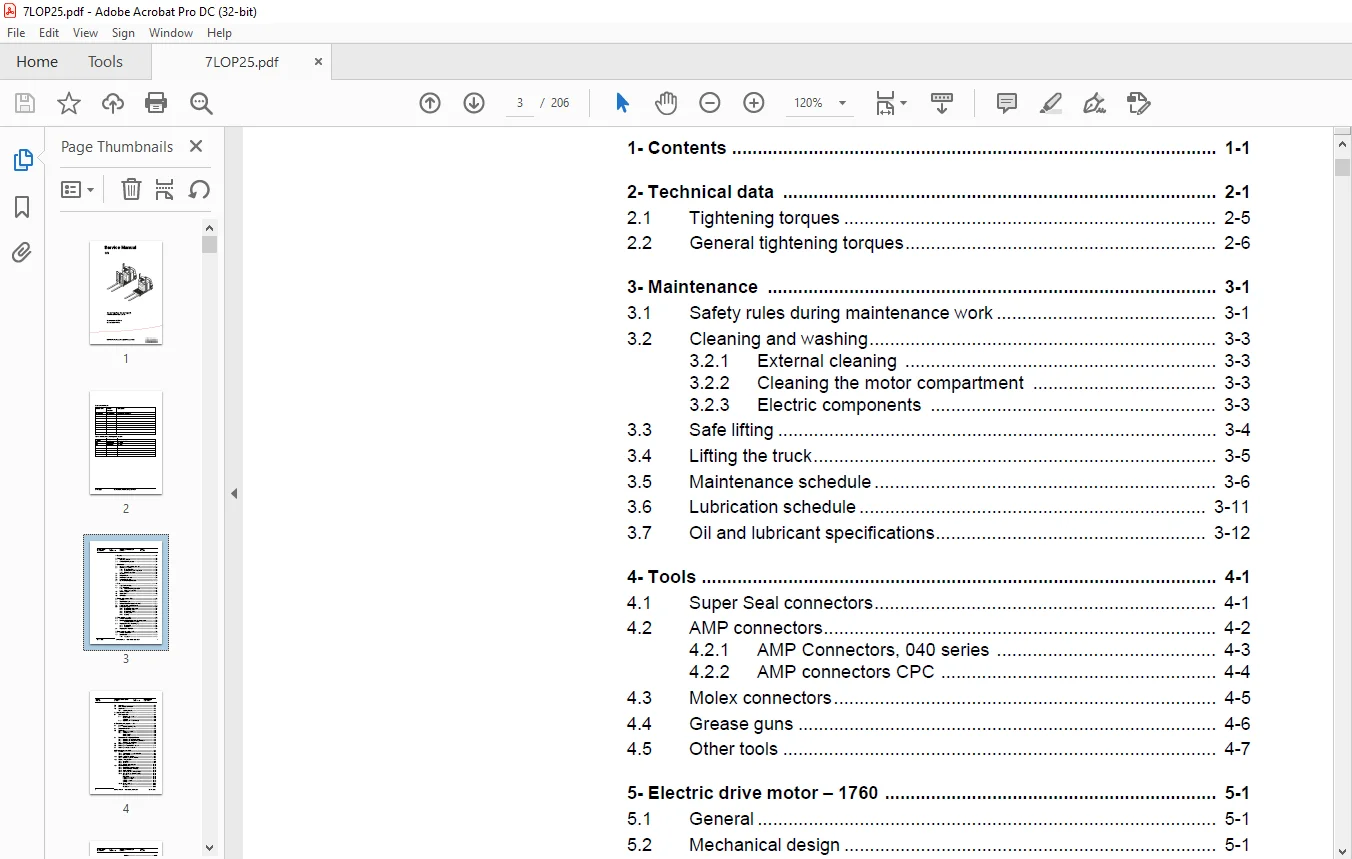
TABLE OF CONTENTS:
Toyota Forklift 7LOP10CW 7LOP10CF Service Manual SN 931876 – PDF DOWNLOAD
2- Technical data..............................................................  9
	2.1 Tightening torques..................................................... 13
	2.2 General tightening torques............................................. 14
3- Maintenance................................................................. 15
	3.1 Safety rules during maintenance work................................... 15
	3.2 Cleaning and washing................................................... 17
		3.2.1 External cleaning................................................ 17
		3.2.2 Cleaning the motor compartment................................... 17
		3.2.3 Electric components.............................................. 17
	3.3 Safe lifting........................................................... 18
	3.4 Lifting the truck...................................................... 19
	3.5 Maintenance schedule................................................... 20
	3.6 Lubrication schedule................................................... 25
	3.7 Oil and lubricant specifications....................................... 26
4- Tools....................................................................... 27
	4.1 Super Seal connectors.................................................. 27
	4.2 AMP connectors......................................................... 28
		4.2.1 AMP Connectors, 040 series....................................... 29
		4.2.2 AMP connectors CPC............................................... 30
	4.3 Molex connectors....................................................... 31
	4.4 Grease guns............................................................ 32
	4.5 Other tools............................................................ 33
5- Electric drive motor - 1760................................................. 35
	5.1 General................................................................ 35
	5.2 Mechanical design...................................................... 35
	5.3 Disassembly of the motor from the truck................................ 36
	5.4 Assembly of the motor in the truck..................................... 36
	5.5 Service and repairs.................................................... 37
		5.5.1 Disassembly of the motor......................................... 37
		5.5.2 Disassembly, N side.............................................. 38
		5.5.3 Disassembly, D side.............................................. 38
		5.5.4 Wearing parts.................................................... 38
		5.5.5 Cleaning......................................................... 39
6- Driving unit/gear - 2550.................................................... 41
	6.1 Included components.................................................... 42
	6.2 Disassembly/Assembly Leakage from top cover............................ 43
		Assembly is done in reverse............................................ 43
	6.3 Replacing the drive axle jointing ring................................. 44
		6.3.1 Disassembly...................................................... 44
		6.3.2 Assembly......................................................... 45
	6.4 Replacing the wheel bolt............................................... 46
7- Electromagnetic brake - 3370................................................ 47
	7.1 Included components.................................................... 48
	7.2 Disassembly............................................................ 48
		7.2.1 Inspection....................................................... 48
	7.3 Assembly............................................................... 49
	7.4 Manual release of the brake............................................ 49
	7.5 Adjustment............................................................. 49
		7.5.1 Adjusting the play............................................... 49
8- Support wheels - 3500....................................................... 51
	8.1 Main components........................................................ 51
		8.1.1 Replacing the wheel.............................................. 52
			Disassembly........................................................ 52
			Assembly........................................................... 52
		8.1.2 Replacing the wheel bearings..................................... 52
9- Electrical steering system - 4300........................................... 53
	9.1 General................................................................ 53
		9.1.1 Electrical steering servo........................................ 54
	9.2 Component overview..................................................... 55
	9.3 Adjustment............................................................. 57
		9.3.1 Reference sensor................................................. 57
		9.3.2 Calibration...................................................... 57
			Parameter 36....................................................... 57
			Parameter 37....................................................... 57
	9.4 Disassembly/assembly of pushbuttons.................................... 58
		9.4.1 Replacing the hornbutton/switch.................................. 58
		9.4.2 Replacing the lifting/lowering pushbutton........................ 59
		9.4.3 Replacing the pushbutton......................................... 59
	9.5 Replacing the potentiometer............................................ 60
	9.6 Replacing the inductive brake sensor................................... 63
	9.7 Replacing the viscous damper........................................... 66
10- Electrical systems - 5000.................................................. 69
	10.1 General............................................................... 69
		10.1.1 Software/hardware order numbers................................. 69
		10.1.2 Nomenclature.................................................... 70
	10.2 Electrical equipment overview......................................... 71
		10.2.1 Electric component overview..................................... 73
	10.3 Electrical wiring diagram............................................. 76
		10.3.1 Symbol list..................................................... 76
		10.3.2 Overview........................................................ 77
		10.3.3 Detailed wiring diagram......................................... 78
	10.4 Functional description................................................ 87
		10.4.1 Description of steering system.................................. 92
		10.4.2 Spider expansion unit (SEU)..................................... 93
		10.4.3 Speed limitation................................................ 94
		10.4.4 Hour meter and battery condition................................ 95
		10.4.5 TLS - Truck log system (optional)............................... 96
			General............................................................ 96
			Registration....................................................... 96
			Logging in/out SD16................................................ 96
			Logging in/out S16................................................. 96
			Collision sensor................................................... 97
			Settings........................................................... 97
		10.4.6 ID unit (optional).............................................. 98
			General............................................................ 98
			Installation....................................................... 98
			Settings........................................................... 99
	10.5 Parameters & adjustments..............................................101
		10.5.1 General.........................................................101
		10.5.2 Displaying parameters - without the CAN service key.............101
		10.5.3 Adjusting operator parameters - without the CAN service key.....102
		10.5.4 Displaying & changing parameters - CAN service key connected....102
			Changing a parameter...............................................103
		10.5.5 List of operator parameters.....................................104
		10.5.6 Description of operator parameters..............................105
			#1 - Speed, Fork direction.........................................105
			# 2 - Speed, Drive wheel direction.................................105
			# 3 - Acceleration.................................................105
			# 4 - Neutral braking force........................................105
			# 5 - Travel speed, cabin > 0.5 m..................................105
			# 6 - Travel speed, walking at side................................105
			# 7 - Neutral braking, walking at side.............................105
		10.5.7 List of Service parameters......................................106
		10.5.8 Description of Service parameter................................107
			# 10 - PIN code....................................................107
			To enter a new PIN-code:...........................................108
			To remove an existing PIN-code:....................................108
			# 11 - Reverse braking force.......................................109
			# 14 - Creep speed.................................................109
			#15 - Non-configurable options.....................................109
			Setting Non-configurable options...................................109
			#16 - Configurable option #1.......................................110
			#17 - Configurable option #2.......................................110
			#19 - Configurable option #4.......................................110
			# 20 - Hour meter selection........................................111
			# 21 - Battery size................................................112
			# 22 - Machine type................................................113
			# 23 - Function selection..........................................113
			# 24 - Special request.............................................113
			# 25 - Service interval............................................113
			# 28 - Button selection............................................113
			# 35 - Automatic log-off...........................................114
			# 36 - Steer servo calibration.....................................114
			# 37 - Steering offset.............................................115
			# 39 - Log-in method & operator parameter access...................115
			Extended keypad - General..........................................116
			Extended keypad - Programming......................................116
		10.5.9 Configurable “Option” parameters................................118
			General............................................................118
			Parameter #16 to #19 configurable options..........................119
			Setting Configurable options.......................................120
	10.6 Diagnostic and troubleshooting........................................131
		10.6.1 General.........................................................131
		10.6.2 Fault code history..............................................132
		10.6.3 List of fault codes.............................................132
		10.6.4 Transistor regulator troubleshooting and error codes............138
			General............................................................138
			Transistor regulator errors........................................139
			Resetting errors...................................................140
			Safety.............................................................140
		10.6.5 Built-in Test Function..........................................141
			Digital inputs/outputs test mode...................................142
		10.6.6 Transistor regulator inputs.....................................142
			Transistor regulator outputs.......................................143
			Digital input of logic card [A2]...................................143
			Digital input/output to expansion unit [A36].......................144
			Digital input/output to expansion unit [A36] (Option)..............144
			Extra functions....................................................145
		10.6.7 Display test mode...............................................145
	10.7 Technical specifications - Curtis 1243................................146
11- Hydraulic system - 6000....................................................147
	11.1 7LOP10CW..............................................................147
		11.1.1 General.........................................................147
		11.1.2 Hydraulic drawing and symbol list...............................148
			Symbol list........................................................148
		11.1.3 Description.....................................................149
			Lift...............................................................149
			Lowering...........................................................149
			Operating pressure.................................................149
			Relief valve.......................................................149
			Pressure sensor....................................................149
	11.2 7LOP10CF..............................................................150
		11.2.1 General.........................................................150
		11.2.2 Hydraulic drawing and symbol list...............................151
			Symbol list........................................................152
		11.2.3 Description.....................................................152
			Cabin lifting......................................................152
			Cabin lowering.....................................................152
			Initial forks......................................................153
			Initial forks lowering.............................................153
			Operating pressure.................................................153
			Relief valve.......................................................153
			Check valve for the cabin / forks cylinders (3)....................153
			Pressure sensors, B10/B11..........................................153
	11.3 Adjustments...........................................................154
		Adjusting the pressure limiting valve..................................154
12- Main lift chain system - 7120..............................................155
	12.1 General...............................................................155
	12.2 Checking the chain setting............................................155
	12.3 Chain inspection......................................................155
		12.3.1 Noise...........................................................155
		12.3.2 Surface rust....................................................155
		12.3.3 Rusty links.....................................................155
		12.3.4 Stiff links.....................................................156
		12.3.5 Bolt rotation...................................................156
		12.3.6 Loose bolts.....................................................156
		12.3.7 Outline wear....................................................157
		12.3.8 Stretching......................................................158
		12.3.9 Damage..........................................................159
		12.3.10 Damaged discs..................................................159
		12.3.11 Damaged bolts..................................................159
		12.3.12 Dirty chain....................................................159
	12.4 Cleaning..............................................................159
	12.5 Lubrication...........................................................160
13- Fork carriage - 7420.......................................................161
	13.1 Included components...................................................161
	13.2 Dismounting of the mast carriage......................................163
	13.3 Adjusting the play....................................................163
	13.4 Roller replacement....................................................163
	13.5 Dismounting of the initial fork carriage..............................164
14- TruckCom...................................................................165
	14.1 General...............................................................165
	14.2 Connection............................................................165
	14.3 Layout................................................................166
		14.3.1 Main program screen.............................................166
		14.3.2 Nodes...........................................................166
		14.3.3 Icons...........................................................167
		14.3.4 Tool buttons and menu bar.......................................167
		14.3.5 Information window..............................................168
		14.3.6 Status bar......................................................168
	14.4 Connection function...................................................168
	14.5 Disconnection function................................................168
	14.6 Downloading program function..........................................169
		14.6.1 Normal downloading (truck with key).............................169
		14.6.2 Normal downloading (truck with keypad)..........................169
		14.6.3 Emergency downloading (truck with keypad).......................170
		14.6.4 Emergency downloading (truck with keypad).......................170
		14.6.5 Downloading in old versions of logic card.......................170
	14.7 Truck report function.................................................171
	14.8 Parameters function...................................................172
	14.9 Diagnostics function..................................................172
		14.9.1 Representation of signal colours................................173
		14.9.2 “Tiller arm” tab................................................173
		14.9.3 “Drive Controller” tab (transistor regulator driving)...........174
		14.9.4 “Pump controller” tab (transistor regulator pump)...............175
		14.9.5 “EPS” (steering servo tab)......................................176
		14.9.6 SEU tab (Extra I/O module)......................................177
	14.10 Other menu functions.................................................177
		14.10.1 Save to file...................................................177
		14.10.2 Download from file.............................................177
		14.10.3 Reset CAN adapter..............................................178
		14.10.4 Delete error code log..........................................178
		14.10.5 Reset hour meter...............................................178
		14.10.6 Read error code log............................................178
		14.10.7 Adjust date and time...........................................178
		14.10.8 Adjusting the hour meter on older cards........................178
		14.10.9 Help...........................................................178
			About the TruckCom application.....................................178
		14.10.10 Exit..........................................................178
	14.11 Specifications.......................................................179
	14.12 Installation.........................................................179
		14.12.1 Installation on a PC with Windows® 95/98.......................179
		14.12.2 Installation on a PC with Windows XP/ 2000.....................180
			Changes in Windows® control panel..................................183
		14.12.3 Installation on a PC with Windows NT...........................186
		14.12.4 In case of communication problems with CAN.....................186
		14.12.5 To uninstall...................................................186
15- Destruction instructions...................................................187
	15.1 General...............................................................187
	15.2 Procedure.............................................................187
	15.3 Abbreviations.........................................................188
	15.4 Sorting...............................................................188
	15.5 Hoods, hatches (0340).................................................189
		15.5.1 Dismantling.....................................................189
		15.5.2 Material handling...............................................189
	15.6 Hoods, hatches (0340).................................................190
		15.6.1 Dismantling.....................................................190
		15.6.2 Material handling...............................................190
	15.7 Seat, cushions (0620).................................................191
		15.7.1 Dismantling.....................................................191
		15.7.2 Material handling...............................................191
	15.8 Wall/floor covering (0670)............................................192
		15.8.1 Dismantling.....................................................192
		15.8.2 Material handling...............................................192
	15.9 Electric motors (1700)................................................193
		15.9.1 Dismantling.....................................................193
		15.9.2 Material handling...............................................193
	15.10 Drive assembly/gear (2550)...........................................194
		15.10.1 Dismantling....................................................194
		15.10.2 Material handling..............................................194
	15.11 Wheels (3500)........................................................195
		15.11.1 Dismantling....................................................195
		15.11.2 Material handling..............................................195
	15.12 Steering arm (4110)..................................................196
		15.12.1 Dismantling....................................................196
		15.12.2 Material handling..............................................196
	15.13 General electronic equipment (5100)..................................197
		15.13.1 Dismantling....................................................197
		15.13.2 Material handling..............................................197
	15.14 Battery cut out connector/ contactor (5190)..........................198
		15.14.1 Dismantling....................................................198
		15.14.2 Material handling..............................................198
	15.15 Expansion unit “SEU”(5730)...........................................199
		15.15.1 Dismantling....................................................199
		15.15.2 Material handling..............................................199
	15.16 Hydraulic unit (6100)................................................200
		15.16.1 Dismantling....................................................200
		15.16.2 Material handling..............................................200
	15.17 Hydraulic lines chassis (6230) and main lift cylinders (6610)........201
		15.17.1 Dismantling....................................................201
		15.17.2 Material handling..............................................201
	15.18 Frame/chassis (7420).................................................202
		15.18.1 Dismantling....................................................202
		15.18.2 Material handling..............................................202
	15.19 Charger adaptor (9380)...............................................203
		15.19.1 Dismantling....................................................203
		15.19.2 Material handling..............................................203
	15.20 Other extra equipment, tuck log device (9420)........................204
		15.20.1 Dismantling....................................................204
		15.20.2 Material handling..............................................204
	15.21 Other extra equipment, writing table (9500)..........................205
		15.21.1 Dismantling....................................................205
		15.21.2 Material handling..............................................205
IMAGES PREVIEW OF THE MANUAL:
Contact us: [email protected]
PLEASE NOTE:
- This is the same manual used by the dealers to diagnose and troubleshoot your vehicle
- You will be directed to the download page as soon as the purchase is completed. The whole payment and downloading process will take anywhere between 2-5 minutes
- Need any other service / repair / parts manual, please feel free to contact [email protected] . We still have 50,000 manuals unlisted
S.V