Toyota Forklift 7LOP12 7LOP12P 7LOP25 7LOP25P Service Manual SN 932596 – PDF DOWNLOAD
$28.95
Toyota Forklift 7LOP12 7LOP12P 7LOP25 7LOP25P Service Manual SN 932596 – PDF DOWNLOAD
Description
Toyota Forklift 7LOP12 7LOP12P 7LOP25 7LOP25P Service Manual SN 932596 – PDF DOWNLOAD
FILE DETAILS:
Toyota Forklift 7LOP12 7LOP12P 7LOP25 7LOP25P Service Manual SN 932596 – PDF DOWNLOAD
Language : English
Pages : 260
Downloadable : Yes
File Type : PDF
DESCRIPTION:
Toyota Forklift 7LOP12 7LOP12P 7LOP25 7LOP25P Service Manual SN 932596 – PDF DOWNLOAD
Maintenance:
To assure maximum safety and minimum downtime, all items in the service programme should be covered. The service intervals are only guidelines and need not be strictly followed. The operator of the truck should adapt these to local requirements, however, it is important that the minimum requirements as stated by TOYOTA are observed.
The service intervals are based on truck operating hours and can be adapted to most common 8-hour shifts. When calculating the service intervals, the following operating hours have been used:
Day time:08.00-17.00 (20 hours/week)
Double shift:06.00-14.00, 14.00-22.00 (40 hours/week)
Triple shift:06.00-14.00, 14.00-22.00, 22.00-06.00
(60 hours/week)
Make sure the truck receives the necessary regular maintenance service according to the maintenance schedule. The truck’s safety, efficiency and service life rely on the service and maintenance the truck receives.
For service and repairs, only use spare parts approved by TOYOTA.
3.1 Safety rules during maintenance work
Only technicians who have received the necessary training for service and repairs of this truck type may carry out service and repair work.
•Do not perform any repair work on the truck unless properly trained and possessing the necessary skills to perform such work.
•Keep the service site clean. Oil and water on the floor could make it slippery.
•Never wear loose items and jewellery when working on the truck.
TABLE OF CONTENTS:
Toyota Forklift 7LOP12 7LOP12P 7LOP25 7LOP25P Service Manual SN 932596 – PDF DOWNLOAD
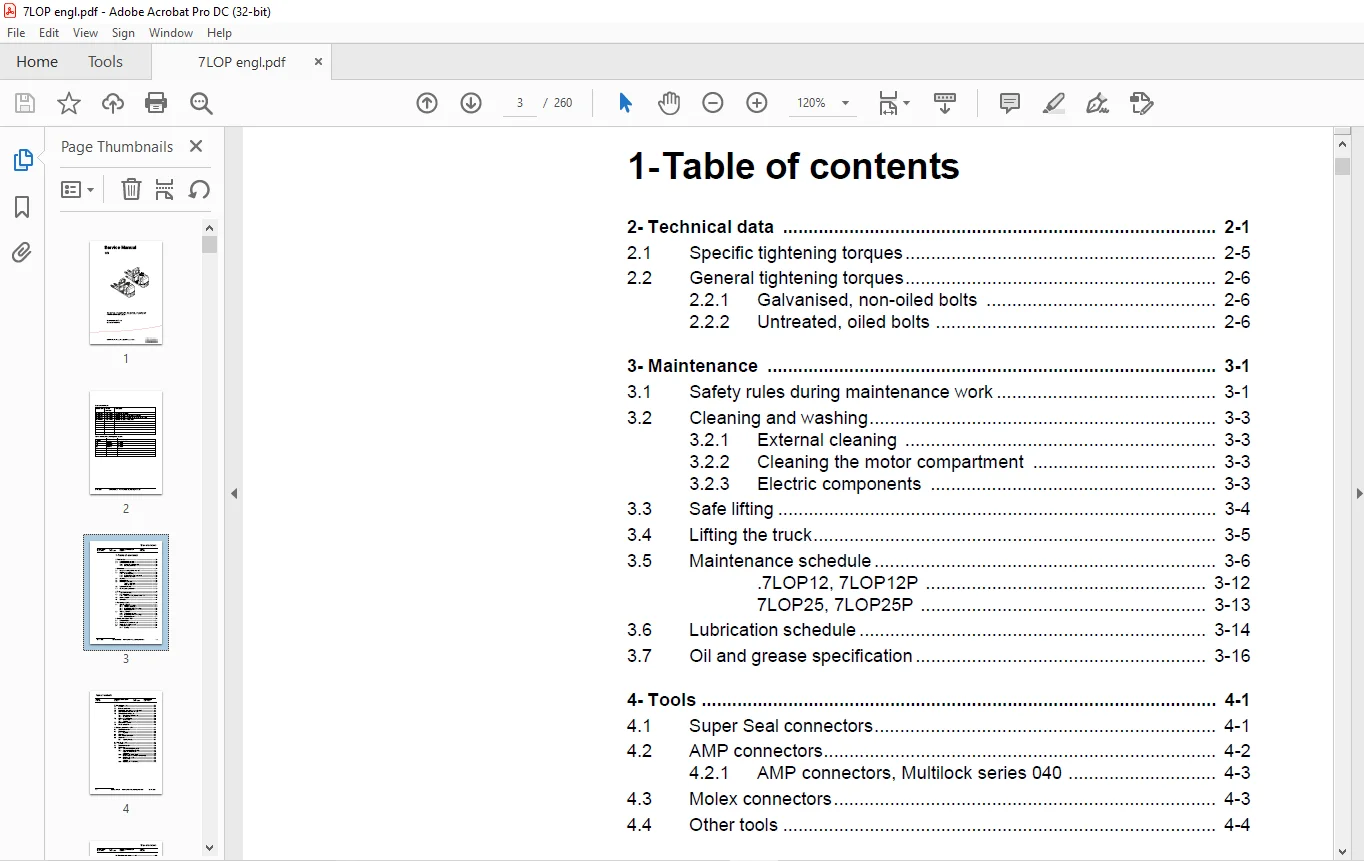
1- Table of contents...............................................................  3
2- Technical data.................................................................. 11
	2.1 Specific tightening torques................................................ 15
	2.2 General tightening torques................................................. 16
		2.2.1 Galvanised, non-oiled bolts.......................................... 16
		2.2.2 Untreated, oiled bolts............................................... 16
3- Maintenance..................................................................... 17
	3.1 Safety rules during maintenance work....................................... 17
	3.2 Cleaning and washing....................................................... 19
		3.2.1 External cleaning.................................................... 19
		3.2.2 Cleaning the motor compartment....................................... 19
		3.2.3 Electric components.................................................. 19
	3.3 Safe lifting............................................................... 20
	3.4 Lifting the truck.......................................................... 21
	3.5 Maintenance schedule....................................................... 22
		.7LOP12, 7LOP12P........................................................... 28
		7LOP25, 7LOP25P............................................................ 29
	3.6 Lubrication schedule....................................................... 30
	3.7 Oil and grease specification............................................... 32
4- Tools........................................................................... 33
	4.1 Super Seal connectors...................................................... 33
	4.2 AMP connectors............................................................. 34
		4.2.1 AMP connectors, Multilock series 040................................. 35
	4.3 Molex connectors........................................................... 35
	4.4 Other tools................................................................ 36
5- Fork carriage - 0380............................................................ 39
	5.1 7LOP12, 7LOP12P............................................................ 39
		5.1.1 Component overview................................................... 39
		5.1.2 Verifying lateral play............................................... 40
		5.1.3 Disassembly of the fork carriage..................................... 41
		5.1.4 Roller replacement................................................... 41
	5.2 7LOP25, 7LOP25P............................................................ 42
		5.2.1 Included components.................................................. 42
		5.2.2 Disassembly of the fork carriage..................................... 44
		5.2.3 Roller replacement................................................... 45
6- Electric drive motor - 1760..................................................... 47
	6.1 Component parts............................................................ 47
	6.2 Removing the motor from the truck.......................................... 49
	6.3 Refitting the motor in the truck........................................... 50
	6.4 Service and repairs........................................................ 50
		6.4.1 Cleaning............................................................. 50
7- Drive unit/gear - 2550.......................................................... 51
	7.1 General.................................................................... 51
	7.2 Included components........................................................ 52
	7.3 Disassembly of the drive unit from the truck............................... 53
	7.4 Assembly of the drive unit in the truck.................................... 53
	7.5 Oil inspection or changing oil............................................. 54
		7.5.1 Oil inspection/replenishment......................................... 54
		7.5.2 Changing oil......................................................... 54
	7.6 Replacing the gasket ring.................................................. 54
		7.6.1 Disassembly.......................................................... 54
		7.6.2 Assembly............................................................. 55
	7.7 Leakage from top cover..................................................... 55
	7.8 Pin bolt replacement....................................................... 56
8- Electromagnetic brake - 3370.................................................... 57
	8.1 Component overview......................................................... 57
	8.2 Disassembly................................................................ 58
		8.2.1 Inspection........................................................... 58
	8.3 Assembly................................................................... 59
	8.4 Manual release of the brake................................................ 59
	8.5 Adjustment................................................................. 59
		8.5.1 Adjusting the play................................................... 59
9- Swivel wheel - 3540............................................................. 61
	9.1 General.................................................................... 61
	9.2 Component overview......................................................... 62
	9.3 Maintenance................................................................ 63
		9.3.1 Swivel wheel height inspection....................................... 63
		9.3.2 Swivel wheel height adjustment....................................... 65
			Adjust the swivel wheel................................................ 65
			Adjustment............................................................. 65
		9.3.3 Replacing the swivel wheel........................................... 65
			Disassembly of the swivel wheel assembly............................... 65
		9.3.4 Replacing the wheel.................................................. 66
			Disassembly............................................................ 66
			Assembly............................................................... 66
		9.3.5 Replacing the wheel bearing.......................................... 66
10- Electrical steering system - 4300.............................................. 67
	10.1 General................................................................... 67
		10.1.1 Electrical steering servo........................................... 68
	10.2 Component overview........................................................ 69
	10.3 Adjustment................................................................ 71
		10.3.1 Reference sensor.................................................... 71
		10.3.2 Calibration......................................................... 71
			Parameter 36........................................................... 71
			Parameter 37........................................................... 71
	10.4 Disassembly/assembly of pushbuttons....................................... 72
		10.4.1 Replacing the hornbutton/switch..................................... 72
		10.4.2 Replacing the lifting/lowering pushbutton........................... 73
		10.4.3 Replacing the pushbutton............................................ 73
	10.5 Replacing the potentiometer............................................... 74
	10.6 Inspection and replacement of the lateral movement line (Ergo version).... 77
	10.7 Replacing the inductive brake sensor...................................... 79
	10.8 Replacing the viscous damper.............................................. 82
11- Electrical systems - 5000...................................................... 85
	11.1 General................................................................... 85
		11.1.1 Software/hardware order numbers..................................... 85
		11.1.2 Nomenclature........................................................ 86
	11.2 Electrical equipment overview............................................. 87
		11.2.1 Electric component overview......................................... 90
	11.3 Electrical wiring diagram................................................. 93
		11.3.1 Symbol list......................................................... 93
		11.3.2 Overview............................................................ 94
		11.3.3 Detailed wiring diagram 7LOP12...................................... 95
		11.3.4 Detailed wiring diagram 7LOP12P.....................................102
		11.3.5 Detailed wiring diagram 7LOP25......................................110
		11.3.6 Detailed wiring diagram 7LOP25P.....................................116
	11.4 Functional description....................................................123
		11.4.1 Description of the steering servo system............................135
		11.4.2 Spider expansion unit (SEU).........................................135
		11.4.3 Speed limitation....................................................137
		11.4.4 Hour meter and battery condition....................................139
		11.4.5 TLS - Truck log system (optional)...................................140
			General................................................................140
			Registration...........................................................140
			Logging in/out SD16....................................................140
			Logging in/out S16.....................................................140
			Collision sensor.......................................................141
			Settings...............................................................141
		11.4.6 ID unit (optional)..................................................141
	11.5 Parameters & adjustments..................................................142
		11.5.1 General.............................................................142
		11.5.2 Displaying parameters - without the CAN service key.................142
		11.5.3 Adjusting operator parameters - without the CAN service key.........143
		11.5.4 Displaying & changing parameters - CAN service key connected........144
			Changing a parameter...................................................144
		11.5.5 List of Operator parameters.........................................146
		11.5.6 Description of operator parameters..................................147
			#1 - Speed, Fork direction.............................................147
			# 2 - Speed, Drive wheel direction.....................................147
			# 3 - Acceleration.....................................................147
			# 4 - Neutral braking force............................................147
			# 5 - Travel speed, platform > 0.5 m...................................147
			# 6 - Travel speed, walking at side....................................147
			# 7 - Neutral braking, walking at side.................................147
		11.5.7 List of Service parameters..........................................148
		11.5.8 Description of Service parameter....................................149
			# 10 - PIN code........................................................149
			To enter a new PIN-code:...............................................150
			To remove an existing PIN-code:........................................150
			# 11 - Reverse braking force...........................................151
			# 14 - Creep speed.....................................................151
			# 15 - Non-configurable options........................................151
			Setting Non-configurable options.......................................151
			#16 - Configurable option #1...........................................152
			#17 - Configurable option #2...........................................152
			#18 - Configurable option #3...........................................152
			#19 - Configurable option #4...........................................152
			# 20 - Hour meter selection............................................153
			# 21 - Battery size....................................................154
			# 22 - Machine type....................................................155
			# 23 - Function selection..............................................155
			# 24 - N/A.............................................................155
			# 25 - Service interval................................................155
			# 28 - Button selection................................................156
			# 35 - Automatic log-off...............................................156
			# 36 - Steer servo calibration.........................................156
			# 37 - Steering offset.................................................157
			# 39 - Log-in method & operator parameter access.......................157
			Extended keypad - General..............................................158
			Extended keypad - Programming..........................................158
		11.5.9 Configurable “Option” Parameters....................................161
			General................................................................161
			Parameter #16 to #19 Configurable options..............................162
			Setting Configurable options...........................................163
	11.6 Diagnostic and troubleshooting............................................172
		11.6.1 General.............................................................172
		11.6.2 Fault code history..................................................173
		11.6.3 List of error codes.................................................174
		11.6.4 Transistor regulator troubleshooting and error codes................180
			General................................................................180
			Transistor regulator errors............................................181
			Resetting errors.......................................................182
			Safety.................................................................182
		11.6.5 Built-in Test Function..............................................183
			Digital inputs/outputs test mode.......................................184
			Transistor regulator inputs............................................184
			Transistor regulator outputs...........................................185
			Digital input of logic card [A2].......................................185
			Digital input/output to expansion unit [A36]...........................186
			Extra functions........................................................186
		11.6.6 Display test mode...................................................187
	11.7 Technical specifications - Curtis 1243....................................188
12- Hydraulic system - 6000........................................................189
	12.1 Hydraulic component overview..............................................189
	12.2 Hydraulic diagrams........................................................190
		12.2.1 Component overview..................................................192
	12.3 Functional description....................................................193
		12.3.1 Fork lifting........................................................193
		12.3.2 Fork lowering.......................................................193
		12.3.3 Platform lifting....................................................193
		12.3.4 Platform lowering...................................................193
		12.3.5 Operating pressure..................................................193
		12.3.6 Relief valve........................................................194
		12.3.7 Platform cylinder check valve.......................................194
		12.3.8 Pressure sensor.....................................................194
	12.4 Adjustments...............................................................195
		12.4.1 Adjusting the pressure limiting valve...............................195
	12.5 Tools.....................................................................196
13- Main lift chain system - 7120..................................................197
	13.1 General...................................................................197
	13.2 Checking the chain setting................................................197
	13.3 Chain inspection..........................................................197
		13.3.1 Noise...............................................................197
		13.3.2 Surface rust........................................................197
		13.3.3 Rusty links.........................................................197
		13.3.4 Stiff links.........................................................198
		13.3.5 Bolt rotation.......................................................198
		13.3.6 Loose bolts.........................................................198
		13.3.7 Outline wear........................................................199
		13.3.8 Stretching..........................................................200
		13.3.9 Damage..............................................................200
		13.3.10 Damaged discs......................................................201
		13.3.11 Damaged bolts......................................................201
		13.3.12 Dirty chain........................................................201
	13.4 Cleaning..................................................................201
	13.5 Lubrication...............................................................202
14- Platform - 9130................................................................203
	14.1 General...................................................................203
	14.2 Component overview........................................................204
	14.3 Adjustment................................................................206
		14.3.1 Outer side guide....................................................207
15- TruckCom.......................................................................209
	15.1 General...................................................................209
	15.2 Connection................................................................210
	15.3 Layout....................................................................211
		15.3.1 Main program screen.................................................211
		15.3.2 Nodes...............................................................211
		15.3.3 Icons...............................................................212
		15.3.4 Tool buttons and menu bar...........................................212
		15.3.5 Information window..................................................213
		15.3.6 Status bar..........................................................213
	15.4 Connection function.......................................................213
	15.5 Disconnection function....................................................213
	15.6 Downloading program function..............................................214
		15.6.1 Normal downloading (truck with key).................................214
		15.6.2 Normal downloading (truck with keypad)..............................214
		15.6.3 Emergency downloading (truck with keypad)...........................215
		15.6.4 Emergency downloading (truck with keypad)...........................215
		15.6.5 Downloading in old versions of logic card...........................215
	15.7 Truck report function.....................................................216
	15.8 Parameters function.......................................................217
		15.8.1 PIN-code............................................................218
		15.8.2 Hour meters.........................................................219
	15.9 Diagnostics function......................................................219
		15.9.1 Representation of signal colours....................................220
		15.9.2 “Tiller arm” tab....................................................220
		15.9.3 “Drive Controller” tab (transistor regulator driving)...............221
		15.9.4 “Pump controller” tab (transistor regulator pump)...................222
		15.9.5 “EPS” (steering servo tab)..........................................223
		15.9.6 SEU tab (Extra I/O module)..........................................224
	15.10 Other menu functions.....................................................224
		15.10.1 Save to file.......................................................224
		15.10.2 Download from file.................................................225
		15.10.3 Reset CAN adapter..................................................225
		15.10.4 Delete error code log..............................................225
		15.10.5 Reset hour meter...................................................225
		15.10.6 Read error code log................................................225
		15.10.7 Adjust date and time...............................................225
		15.10.8 Adjusting the hour meter on older cards............................225
		15.10.9 Help...............................................................225
			About the TruckCom application.........................................225
		15.10.10 Exit..............................................................226
	15.11 Specifications...........................................................226
	15.12 Installation.............................................................226
		15.12.1 Installation on a PC with Windows® 95/98...........................226
		15.12.2 Installation on a PC with Windows XP/2000..........................228
		15.12.3 Installation on a PC with Windows NT...............................228
		15.12.4 In case of communication problems with CAN.........................228
	15.13 Installation of the CPC-USB interface....................................229
	15.14 To uninstall.............................................................231
16- Destruction instructions.......................................................233
	16.1 General...................................................................233
	16.2 Procedure.................................................................233
	16.3 Abbreviations.............................................................233
	16.4 Sorting...................................................................234
	16.5 Hoods, hatches (0340).....................................................235
		16.5.1 Disassembly.........................................................235
		16.5.2 Material handling...................................................235
	16.6 Battery cover (0340)......................................................236
		16.6.1 Disassembly.........................................................236
		16.6.2 Material handling...................................................236
	16.7 Frame/chassis (0300) and fork frame (0380/7000)...........................237
		16.7.1 Disassembly.........................................................237
		16.7.2 Material handling...................................................237
	16.8 Seat, cushions (0620).....................................................238
		16.8.1 Disassembly.........................................................238
		16.8.2 Material handling...................................................238
	16.9 Wall/floor covering (0670)................................................239
		16.9.1 Disassembly.........................................................239
		16.9.2 Material handling...................................................239
	16.10 Internal fittings (0680).................................................240
		16.10.1 Disassembly........................................................240
		16.10.2 Material handling..................................................240
	16.11 Operator protection (0840)...............................................241
		16.11.1 Disassembly........................................................241
		16.11.2 Material handling..................................................241
	16.12 Electric motors (1700)...................................................242
		16.12.1 Disassembly........................................................242
		16.12.2 Material handling..................................................242
	16.13 Drive assembly/gear (2550)...............................................243
		16.13.1 Disassembly........................................................243
		16.13.2 Material handling..................................................243
	16.14 Wheels (3500)............................................................244
		16.14.1 Disassembly........................................................244
		16.14.2 Material handling..................................................244
	16.15 Steering unit (4110).....................................................245
		16.15.1 Disassembly........................................................245
		16.15.2 Material handling..................................................245
	16.16 General electronic equipment (5100)......................................246
		16.16.1 Disassembly........................................................246
		16.16.2 Material handling..................................................246
	16.17 Battery cut out connector/ contactor (5190)..............................247
		16.17.1 Disassembly........................................................247
		16.17.2 Material handling..................................................247
	16.18 Extra SEU expansion unit (5730)..........................................248
		16.18.1 Disassembly........................................................248
		16.18.2 Material handling..................................................248
	16.19 Hydraulic unit (6100)....................................................249
		16.19.1 Disassembly........................................................249
		16.19.2 Material handling..................................................249
	16.20 Hydraulic lines chassis (6230) and main lift cylinders (6610)............250
		16.20.1 Disassembly........................................................250
		16.20.2 Material handling..................................................250
	16.21 Charger adaptor (9380)...................................................251
		16.21.1 Disassembly........................................................251
		16.21.2 Material handling..................................................251
	16.22 Terminal on board (9410).................................................252
		16.22.1 Disassembly........................................................252
		16.22.2 Material handling..................................................252
	16.23 Other extra equipment, tuck log device (9420)............................253
		16.23.1 Disassembly........................................................253
		16.23.2 Material handling..................................................253
	16.24 Other extra equipment, load support (9500)...............................254
		16.24.1 Disassembly........................................................254
		16.24.2 Material handling..................................................254
	16.25 Other extra equipment, writing table (9500)..............................255
		16.25.1 Disassembly........................................................255
		16.25.2 Material handling..................................................255
	16.26 Other extra equipment, writing table (9500)..............................256
		16.26.1 Disassembly........................................................256
		16.26.2 Material handling..................................................256
	16.27 Other extra equipment, support (9500)....................................257
		16.27.1 Disassembly........................................................257
		16.27.2 Material handling..................................................257
	16.28 Other extra equipment, collision protection (9500).......................258
		16.28.1 Disassembly........................................................258
		16.28.2 Material handling..................................................258
	16.29 Other extra equipment, working cage (9130)...............................259
		16.29.1 Disassembly........................................................259
		16.29.2 Material handling..................................................259
IMAGES PREVIEW OF THE MANUAL:
Contact us: [email protected]
PLEASE NOTE:
- This is the SAME MANUAL used by the dealerships to diagnose your vehicle
- No waiting for couriers / posts as this is a PDF manual and you can download it within 2 minutes time once you make the payment.
- Your payment is all safe and the delivery of the manual is INSTANT – You will be taken to the DOWNLOAD PAGE.
- So have no hesitations whatsoever and write to us about any queries you may have : heydownloadss @gmail.com
S.V