Toyota Forklift 7PLL24 Service Manual SN 723984 – PDF DOWNLOAD
$27.95
Toyota Forklift 7PLL24 Service Manual SN 723984 – PDF DOWNLOAD
Description
Toyota Forklift 7PLL24 Service Manual SN 723984 – PDF DOWNLOAD
FILE DETAILS:
Toyota Forklift 7PLL24 Service Manual SN 723984 – PDF DOWNLOAD
Language : English
Pages : 156
Downloadable : Yes
File Type : PDF
DESCRIPTION:
Toyota Forklift 7PLL24 Service Manual SN 723984 – PDF DOWNLOAD
Introduction, maintenance:
- All points in the service program shall be included to attain the highest safety and a least possible truck downtime. The service intervals are only a guide and do not need to be followed strictly. The truck driver must adapt these to local conditions, but it is important that the intervals meet TOYOTA’s minimum demands.
- The service intervals are based on operating times and can be adapted to most normal 8 hour shifts. The following operating hours have be used when calculating the interval.
Day time:08.00-17.00 (20 hours/week)
2-shifts:06.00-14.00, 14.00-22.00 (40 hours/week)
3-shifts:06.00-14.00, 14.00-22.00, 22.00-06.00 (60 hours/week)
Ensure the truck is given regular maintenance services according to the maintenance schedule. The truck’s safety, efficiency and service life is dependent on the service and maintenance it is given.
Only use TOYOTA approved spare parts during service and repairs
Safety regulations during maintenance work:
Only persons trained in servicing and the repair of this type of truck are qualified to carry out service and repair work.
•Do not carry out any maintenance work on the truck if you do not have the right qualifications and know how to carry out the work.
•Keep the area where service work is done clean. Oil or water will make the floor slippery.
•Never wear loose objects or jewellery when working on the truck.
TABLE OF CONTENTS:
Toyota Forklift 7PLL24 Service Manual SN 723984 – PDF DOWNLOAD
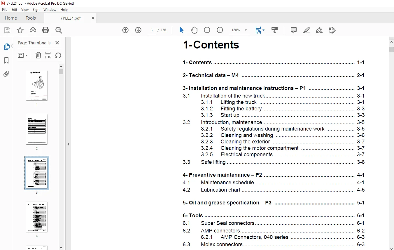
1- Contents...............................................................................  3
2- Technical data - M4....................................................................  7
3- Installation and maintenance instructions - P1......................................... 13
	3.1 Installation of the new truck..................................................... 13
		3.1.1 Lifting the truck........................................................... 13
		3.1.2 Fitting the battery......................................................... 15
		3.1.3 Start up.................................................................... 15
	3.2 Introduction, maintenance......................................................... 17
		3.2.1 Safety regulations during maintenance work.................................. 17
		3.2.2 Cleaning and washing........................................................ 18
		3.2.3 Cleaning the exterior....................................................... 19
		3.2.4 Cleaning the motor compartment.............................................. 19
		3.2.5 Electrical components....................................................... 19
	3.3 Safe lifting...................................................................... 20
4- Preventive maintenance - P2............................................................ 21
	4.1 Maintenance schedule.............................................................. 21
	4.2 Lubrication chart................................................................. 25
5- Oil and grease specification - P3...................................................... 27
6- Tools.................................................................................. 29
	6.1 Super Seal connectors............................................................. 29
	6.2 AMP connectors.................................................................... 30
		6.2.1 AMP Connectors, 040 series.................................................. 31
	6.3 Molex connectors.................................................................. 31
	6.4 Grease guns....................................................................... 32
	6.5 Other tools....................................................................... 33
7- Fork carriage - 0380................................................................... 35
	7.1 Component parts................................................................... 35
	7.2 Dismantling the fork carriage..................................................... 37
	7.3 Replacing the rollers............................................................. 39
8- Engine suspension- 0450................................................................ 41
	8.1 Component parts................................................................... 41
		8.1.1 Component List.............................................................. 42
9- Electric drive motor - 1760............................................................ 43
	9.1 Component parts................................................................... 43
	9.2 Removing the motor from the truck................................................. 44
	9.3 Refitting the motor in the truck.................................................. 45
	9.4 Service and repairs............................................................... 45
		9.4.1 Dismantling N-side.......................................................... 45
		9.4.2 Dismantling D-side.......................................................... 45
		9.4.3 Cleaning.................................................................... 46
10- Mechanical drive gear unit - 2550..................................................... 47
	10.1 Component parts.................................................................. 48
		10.1.1 Technical data............................................................. 49
	10.2 Dismantling/Assembly Leakage from the upper cover................................ 49
	10.3 Replacing the drive shaft gasket................................................. 50
		10.3.1 Dismantling................................................................ 50
		10.3.2 Assembling................................................................. 51
	10.4 Replacing wheel bolt............................................................. 52
11- Electromagnetic brake - 3370.......................................................... 53
	11.1 Component parts.................................................................. 53
	11.2 Dismantling...................................................................... 54
		11.2.1 Inspection................................................................. 54
	11.3 Assembling....................................................................... 55
	11.4 Manual release of the brake...................................................... 55
	11.5 Adjustment....................................................................... 55
		11.5.1 Adjusting the play......................................................... 55
12- Steering system - 4000................................................................ 57
	12.1 Component parts, mechanical steering............................................. 57
	12.2 Component parts, servo steering (Option)......................................... 60
		12.2.1 Steering axle, servo steering (Option)..................................... 61
	12.3 Adjustment, steering............................................................. 65
		12.3.1 Adjusting the steering servo............................................... 65
		12.3.2 Adjusting the steering chain............................................... 65
	12.4 Component parts, tiller arm...................................................... 66
	12.5 Adjustment, tiller arm........................................................... 67
		12.5.1 Adjusting the brake microswitch............................................ 67
	12.6 Tiller arm handle................................................................ 68
	12.7 Dismantling/Assembly, buttons.................................................... 70
		Change from ignition key to keyboard (2).......................................... 70
		Change from keyboard to ignition key (2).......................................... 70
		12.7.1 Replacing the signal button/switch (9, 10)................................. 71
		12.7.2 Replacing the lift/lower button (13)....................................... 71
		12.7.3 Replace the pushbutton (16)................................................ 72
13- Electrical systems - 5000............................................................. 73
	13.1 Electrical parts................................................................. 73
	13.2 Symbol list and electrical diagram............................................... 75
		13.2.1 Electrical wiring diagram 1(5)............................................. 77
		13.2.2 Electrical wiring diagram 2(5)............................................. 78
		13.2.3 Electrical wiring diagram 3(5)............................................. 79
		13.2.4 Electrical wiring diagram 4(5)............................................. 80
		13.2.5 Electrical wiring diagram 5(5)............................................. 81
		13.2.6 Electrical wiring diagram Servo (Option)................................... 82
	13.3 Functional description........................................................... 83
		13.3.1 Starting the truck......................................................... 83
		13.3.2 Driving without using platform and gates, speed £ 6 km/h................... 83
		13.3.3 Driving from platform without using gates,speed £ 6 km/h................... 83
		13.3.4 Driving from platform and using gates, speed ³ 8 km/h...................... 83
		13.3.5 Neutral speed reduction.................................................... 83
		13.3.6 Neutral speed reduction on slopes.......................................... 84
		13.3.7 Braking.................................................................... 84
		13.3.8 Lifting the forks.......................................................... 84
		13.3.9 Lowering the forks......................................................... 84
		13.3.10 Horn...................................................................... 84
	13.4 Hour meter....................................................................... 85
	13.5 Error codes...................................................................... 85
	13.6 Parameters....................................................................... 97
		13.6.1 Driver parameters.......................................................... 97
		13.6.2 Parameter description...................................................... 98
			Parameter 1................................................................... 98
			Parameter 2................................................................... 98
			Parameter 3................................................................... 98
			Parameter 4................................................................... 98
			Parameter 5................................................................... 98
		13.6.3 Service parameters......................................................... 99
		13.6.4 Parameter description......................................................100
			Parameter 10..................................................................100
			Parameter 14..................................................................100
			Parameter 15 - Non-configurable option........................................100
			Parameter 16 - Configurable option #1.........................................101
			Parameter 17 - Configurable option #2.........................................101
			Parameter 18 - Configurable option #3.........................................101
			Parameter 19 - Configurable option #4.........................................101
			Option parameters.............................................................101
			General.......................................................................101
			Parameter #15 Non-configurable options........................................101
			Changing non-configurable options.............................................102
			Parameter #16 to 19 configurable optional functions...........................103
			Changing configurable optional functions......................................104
			Parameter 20..................................................................108
			Parameter 21..................................................................108
			Recommendation on parameter setting for freely ventilated batteries...........109
			Instructions for verifying parameter setting..................................110
			Recommendation on parameter setting for valve- controlled batteries (VRLA)....111
			Instructions for verifying parameter setting..................................112
			Parameter 22..................................................................112
			Parameter 25..................................................................112
			Parameter 28..................................................................112
			Parameter 39..................................................................113
			Login method and driver parameter access......................................113
			Expanded keypad - General.....................................................113
			Expanded keypad - Programming.................................................113
			Service indication............................................................115
	13.7 Part numbers.....................................................................118
	13.8 Transistor panel.................................................................118
		13.8.1 General....................................................................118
	13.9 Diagnostic and troubleshooting...................................................119
		13.9.1 Error codes and troubleshooting............................................119
		13.9.2 Resetting errors...........................................................120
		13.9.3 Safety.....................................................................120
	13.10 Technical specifications - Curtis 1243..........................................121
14- Hydraulic, pneumatic - 6000...........................................................123
	14.1 General..........................................................................123
		14.1.1 Hydraulic diagram..........................................................123
		14.1.2 Symbol list................................................................124
	14.2 Adjustments......................................................................125
		14.2.1 Adjustment of the pressure limit valve.....................................125
	14.3 Cleaning the filter..............................................................126
15- PowerTrak cylinder - 6680.............................................................127
	15.1 Component parts..................................................................127
	15.2 Dismantling the PowerTrak cylinder...............................................128
		15.2.1 Replacing the gaskets in the PowerTrak cylinder............................129
	15.3 Dismantling/assembling the ground pressure springs...............................130
		15.3.1 Component parts............................................................130
		15.3.2 Dismantling................................................................131
		15.3.3 Assembling.................................................................131
		15.3.4 Setting and sealing........................................................131
		15.3.5 Sealing....................................................................132
16- TruckCom..............................................................................133
	16.1 General..........................................................................133
	16.2 Connection.......................................................................133
	16.3 Layout...........................................................................134
		16.3.1 Main program screen........................................................134
		16.3.2 Nodes......................................................................134
		16.3.3 Icons......................................................................135
		16.3.4 Tool buttons and menu bar..................................................135
		16.3.5 Information window.........................................................136
		16.3.6 Status bar.................................................................136
	16.4 Connection function..............................................................136
	16.5 Disconnection function...........................................................136
	16.6 Downloading program function.....................................................137
		16.6.1 Normal downloading (truck with key)........................................137
		16.6.2 Normal downloading (truck with keypad).....................................137
		16.6.3 Emergency downloading (truck with keypad)..................................138
		16.6.4 Emergency downloading (truck with keypad)..................................138
		16.6.5 Downloading in old versions of logic card..................................138
	16.7 Truck report function............................................................139
	16.8 Parameters function..............................................................140
	16.9 Diagnostics function.............................................................140
		16.9.1 Representation of signal colours...........................................141
		16.9.2 “Tiller arm” tab...........................................................141
		16.9.3 “Drive Controller” tab (transistor regulator driving)......................142
		16.9.4 “Pump controller” tab (transistor regulator pump)..........................143
		16.9.5 “EPS” (steering servo tab).................................................144
		16.9.6 SEU tab (Spider Extension Unit)............................................145
	16.10 Other menu functions............................................................145
		16.10.1 Save to file..............................................................145
		16.10.2 Download from file........................................................145
		16.10.3 Reset CAN adapter.........................................................146
		16.10.4 Delete error code log.....................................................146
		16.10.5 Reset hour meter..........................................................146
		16.10.6 Read error code log.......................................................146
		16.10.7 Adjust date and time......................................................146
		16.10.8 Adjusting the hour meter on older cards...................................146
		16.10.9 Help......................................................................146
			About the TruckCom application................................................146
		16.10.10 Exit.....................................................................146
	16.11 Specifications..................................................................147
	16.12 Installation....................................................................147
		16.12.1 Installation on a PC with Windows 95/ 98..................................147
		16.12.2 Installation on a PC with Windows XP/ 2000................................148
			Changes in Windows Control Panel..............................................150
		16.12.3 Installation on a PC with Windows NT......................................153
		16.12.4 In case of communication problems with CAN................................153
		16.12.5 To uninstall..............................................................153
IMAGES PREVIEW OF THE MANUAL:
Need help? Contact: [email protected]
PLEASE NOTE:
- This is the SAME exact manual used by your dealers to fix your vehicle.
- The same can be yours in the next 2-3 mins as you will be directed to the download page immediately after paying for the manual.
- Any queries / doubts regarding your purchase, please feel free to contact [email protected]
S.V