TOYOTA Forklift 7PM18, 7PM20, 7PML20 Service Manual 222995-040 PDF
$26.95
TOYOTA Forklift 7PM18, 7PM20, 7PML20 Service Manual 222995-040 – PDF DOWNLOAD
Valid from serial number: 723984-
Order number: 222995-040
Description
TOYOTA Forklift 7PM18, 7PM20, 7PML20 Service Manual 222995-040 – PDF DOWNLOAD
FILE DETAILS:
TOYOTA Forklift 7PM18, 7PM20, 7PML20 Service Manual 222995-040 – PDF DOWNLOAD
Language : English
Pages : 148
Downloadable : Yes
File Type : PDF
IMAGES PREVIEW OF THE MANUAL:
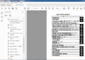
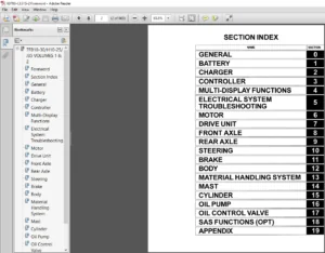
TABLE OF CONTENTS:
TOYOTA Forklift 7PM18, 7PM20, 7PML20 Service Manual 222995-040 – PDF DOWNLOAD
Valid from serial number: 723984-
Order number: 222995-040
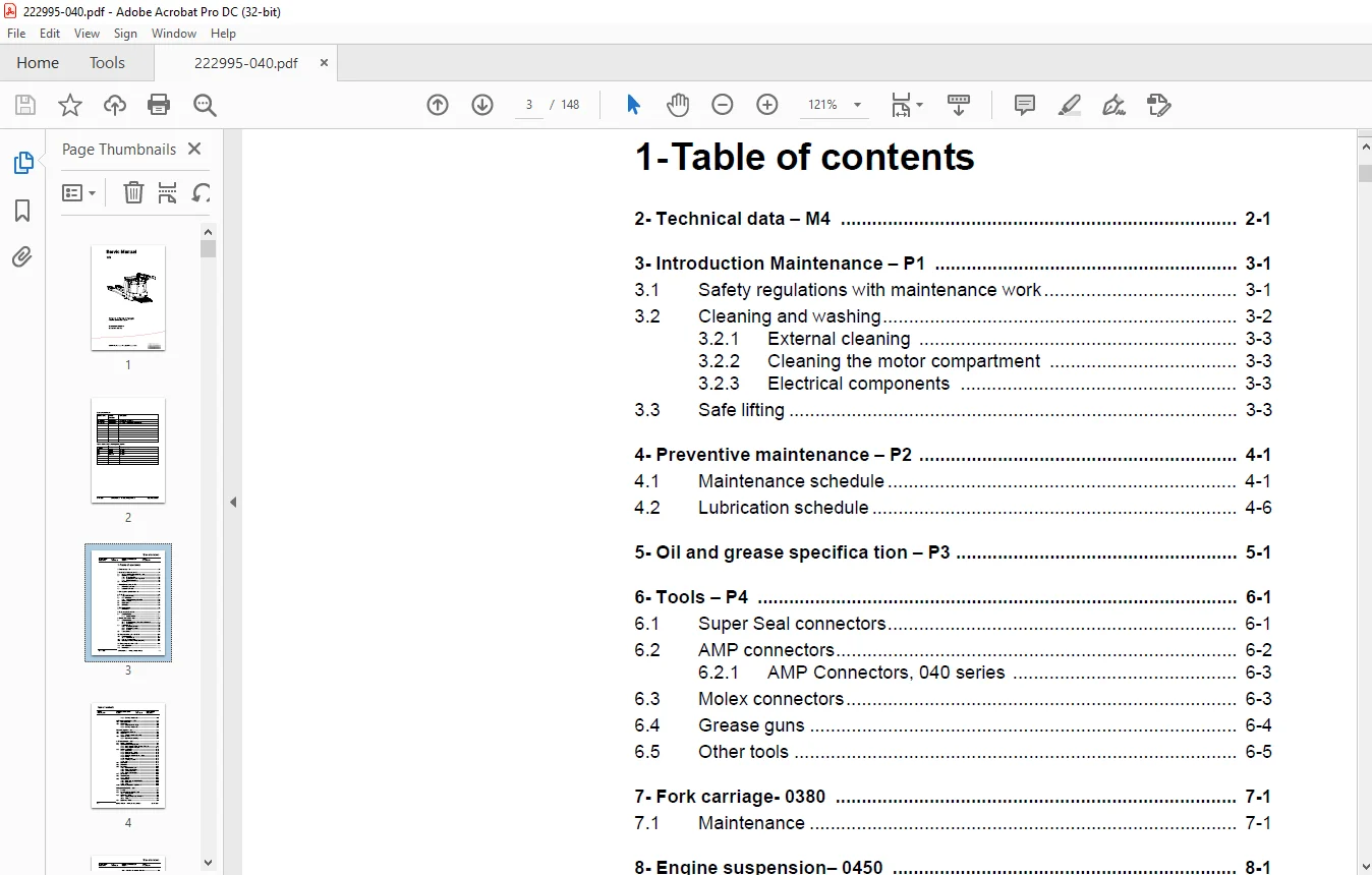
1- Table of contents 3
2- Technical data – M4 7
3- Introduction Maintenance – P1 11
31 Safety regulations with maintenance work 11
32 Cleaning and washing 12
321 External cleaning 13
322 Cleaning the motor compartment 13
323 Electrical components 13
33 Safe lifting 13
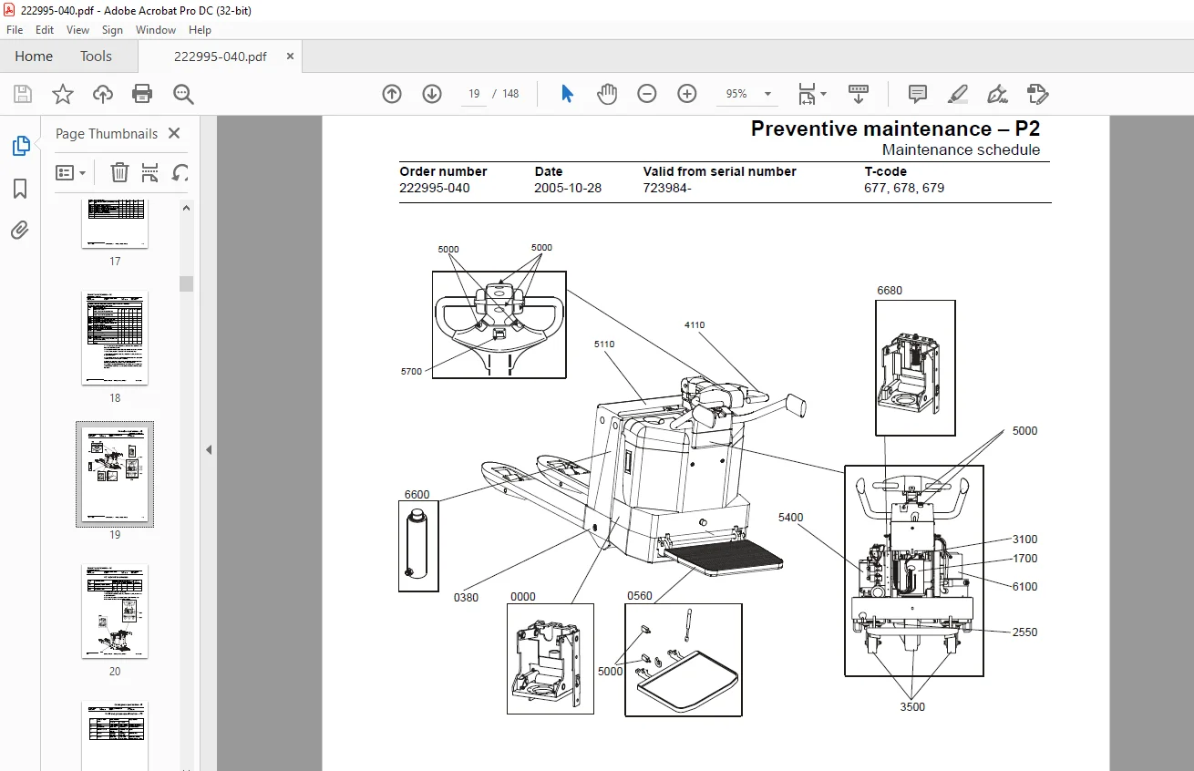
4- Preventive maintenance – P2 15
41 Maintenance schedule 15
42 Lubrication schedule 20
5- Oil and grease specifica tion – P3 21
6- Tools – P4 23
61 Super Seal connectors 23
62 AMP connectors 24
621 AMP Connectors, 040 series 25
63 Molex connectors 25
64 Grease guns 26
65 Other tools 27
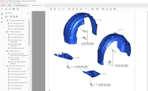
7- Fork carriage- 0380 29
71 Maintenance 29
8- Engine suspension- 0450 31
81 Component parts 31
811 Component List 32
9- Electric drive motor – 1760 33
91 Component parts 33
911 Dismantling/assembling of motor from truck 34
912 Assembling 35
92 Service/Repairs 35
921 Dismantling of motor 35
922 Assembling of motor 36
923 Cleaning 36
93 Technical data 37
10- Mechanical drive gear unit – 2550 39
101 Component parts 40
1011 Technical data 41
102 Leakage from top cover 42
Dismantling 42
Assembling 42
103 Changing of the drive shaft’s sealing ring 42
Dismantling 42
Assembling 43
11- Electro magnetic brake – 3370 45
111 Main components 45
112 Maintenance 46
1121 Exchange of brake disc 46
12- Electro magnetic brake – 3370 47
121 Main components 47
122 Maintenance 48
1221 Basic Adjustment of gap 48
Adjustment: 48
1222 Exchange of brake disc 48
13- Steering system – 4000 49
131 Component parts, tiller arm 49
132 Adjustments 50
1321 Adjusting of brake microswitch 50
133 Tiller arm handle 51
1331 Dismantling/Assembling 52
Change from ignition key to keyboard (2) 53
Change from keyboard to ignition key (2) 53
Changing of signal button/switch (9, 10) 53
Changing of lift/lowering button (13) 54
Changing of pushbutton (16) 54
14- Electrical System – 5000 55
141 Electrical components 55
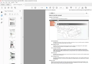
142 Symbol List and Wiring Diagram 57
1421 Wiring diagram 7PM18, 7PM20, 7PML20-6 59
1422 Wiring diagram 7PML20-8 65
143 Operating description 76
1431 Starting truck 76
1432 Driving speed £ 6 km/h 76
1433 Braking in neutral mode 76
1434 Braking in neutral mode on a slope 76
1435 Braking 77
1436 Lifting the forks 77
1437 Lowering the forks 77
1438 Horn 77
144 Hour meter 77
145 Error codes 77
146 Parameters 88
1461 Operator parameters 89
1462 Parameter description 89
Parameter 1 89
Parameter 2 89
Parameter 3 90
Parameter 4 90
Parameter 5 90
1463 Service parameters 90
1464 Parameter description 92
Parameter 10 92
Parameter 14 92
Parameter 15 – Non-configurable option 92
Parameter 16 – Configurable option #1 92
Parameter 17 – Configurable option #2 92
Parameter 18 – Configurable option #3 92
Parameter 19 – Configurable option #4 92
Option parameters 93
General 93
Parameter #15 Non-configurable options 93
Changing non-configurable options 93
Parameter #16 to 19 configurable optional functions 94
Changing configurable optional functions 95
Parameter 20 99
Parameter 21 99
Recommendation on parameter setting for freely ventilated batteries100
Instructions for verifying parameter setting101
Recommendation on parameter setting for valve- controlled batteries (VRLA)102
Instructions for verifying parameter setting103
Parameter 22103
Parameter 25103
Parameter 28103
Parameter 39103
Login method and driver parameter access104
Expanded keypad – General104
Expanded keypad – Programming104
Service indication106
147 Part number108
148 Transistor panel109
1481 General109
149 Troubleshooting110
1491 Error codes and troubleshooting110
1492 Reset error111
1493 Safety111
1410 Technical specifications – Curtis 1243112
15- Hydraulic/Pneumatic – 6000113
151 General113
152 Hydraulic chart and list of symbols113
1521 List of Symbols113
153 Adjustments 7PM18114
1531 Adjusting the pressure limit valve114
1532 Tools115
154 Adjustments 7PM20116
1541 Adjusting the pressure limit valve116
155 Hydraulic chart and list of symbols117
1551 List of Symbols117
156 Adjusting the pressure limit valve118
16- PowerTrak cylinder – 6680119
161 Component parts119
162 Dismantling of PowerTrak cylinder120
17- Battery charger (Inbuilt) – 8340121
171 General121
172 Charging121
173 Troubleshooting and service121
174 Technical data122
175 Charging settings122
1751 Freely ventilated batteries122
1752 Valve regulated batteries123
18- Control/computer equipment – 8700125
181 General125
182 Connection125
183 Layout126
1831 Main program screen126
1832 Nodes126
1833 Icons127
1834 Tool buttons and menu bar128
1835 Information window128
1836 Status bar128
184 Connection function128
185 Disconnection function129
186 Downloading program function129
1861 Normal downloading (truck with key)129
1862 Normal downloading (truck with keypad)130
1863 Emergency downloading (truck with keypad)130
1864 Downloading in old versions of logic card130
1865 Emergency downloading (truck with keypad)131
187 Truck report function132
188 Parameters function133
189 Diagnostics function133
1891 Representation of signal colours134
1892 “Tiller arm” tab134
1893 “Drive Controller” tab (transistor regulator – travel)135
1894 “Pump controller” tab (transistor regulator – pump)136
1895 “EPS” steering servo tab137
1810 Other menu functions138
18101 Save to file138
18102 Download from file138
18103 Reset CAN adapter138
18104 Delete error code log138
18105 Reset hour meter138
18106 Read error code log138
18107 Adjust date and time139
18108 Adjusting the hour meter on older cards139
18109 Help139
About the TruckCom application139
181010 Exit139
1811 Specifications139
1812 Installation140
18121 Installation on a PC with Windows® 95/98140
18122 Installation on a PC with Windows XP/ 2000140
18123 Installation on a PC with Windows NT145
18124 In case of communication problems with CAN145
18125 To uninstall146
S.V 26/02/2025